Page is loading ...

Operating Instructions
thermoIMAGER TIM Connect

MICRO-EPSILON
MESSTECHNIK
GmbH & Co. KG
Koenigbacher Str. 15
94496 Ortenburg / Germany
Tel. +49 (0) 8542 / 168-0
Fax +49 (0) 8542 / 168-90
e-mail [email protected]
www.micro-epsilon.com
Software for thermoIMAGER TIM Infrared camera

thermoIMAGER TIM Connect
Contents
1. Safety ........................................................................................................................................ 7
1.1 Symbols Used ................................................................................................................................................. 7
2. Technical Data .......................................................................................................................... 8
2.1 Functional Principle ......................................................................................................................................... 8
2.2 Functions ......................................................................................................................................................... 8
3. Getting Started ......................................................................................................................... 9
3.1 Software Installation ........................................................................................................................................ 9
3.2 Choice of Camera .......................................................................................................................................... 11
3.3 Choice of Language ...................................................................................................................................... 11
3.4 Software Window (Example) ......................................................................................................................... 12
3.5 Menu and Toolbar (Icons) ............................................................................................................................. 16
3.5.1 Menu ............................................................................................................................................. 16
3.5.2 Toolbar (Icons) .............................................................................................................................. 17
4. Software Configuration .......................................................................................................... 18
4.1 General Settings ............................................................................................................................................ 18
4.1.1 Color Palettes ............................................................................................................................... 18
4.1.2 Temperature Unit .......................................................................................................................... 21
4.1.3 Temperature Range Scaling of Reference Bar............................................................................. 21
4.1.4 Displayed Frame Rate .................................................................................................................. 23
4.1.5 Change of the Title Bar ................................................................................................................. 24
4.1.6 Optimization of Software .............................................................................................................. 24
4.1.7 Lock / Unlock Application ............................................................................................................ 25
4.2 Software Layout ............................................................................................................................................. 26
4.2.1 Displayed Windows ...................................................................................................................... 26
4.2.2 View Bars ...................................................................................................................................... 27
4.2.3 Information within Image .............................................................................................................. 28
4.2.4 Temperatures in Digital Displays .................................................................................................. 29
4.2.5 Layout Managements ................................................................................................................... 30
4.2.6 Assign / Remove Layouts ............................................................................................................. 31
4.2.7 Import / Export Layouts ................................................................................................................ 31
4.2.8 Further Information ....................................................................................................................... 33
4.2.9 Arranging of Thermal Image ........................................................................................................ 33
4.2.10 Mirroring of Displayed Image ....................................................................................................... 33

thermoIMAGER TIM Connect
4.2.11 Rotating of Displayed Image ........................................................................................................ 34
4.2.12 Zooming in Areas of the Displayed Image ................................................................................... 35
4.3 Image Configuration ...................................................................................................................................... 36
4.3.1 Calibration Files ............................................................................................................................ 36
4.3.2 Correction of Camera Calibration ................................................................................................ 36
4.3.3 Detector Heating (Chip Temperature Mode) ................................................................................ 37
4.3.4 Emissivity, Transmissivity, Ambient Temperature ......................................................................... 38
4.3.5 Reference Temperature ................................................................................................................ 39
4.3.6 Changing the Optics (not with thermoMETER TIM 8 / thermoIMAGER TIM 40) ......................... 41
4.3.7 Changing the Temperature Range ............................................................................................... 42
4.3.8 Video Formats (Device Framerate) .............................................................................................. 43
4.4 Imager Interfaces for TIM and thermoIMAGER TIM 40 Camera ................................................................... 44
4.4.1 General ......................................................................................................................................... 44
4.4.2 Process Interface (PIF) for TIM and thermoIMAGER TIM 40 Camera ......................................... 46
4.5 Software Development Kit (SDK) .................................................................................................................. 49
4.5.1 Interprocess Communication (IPC) .............................................................................................. 49
4.5.2 COM-Port ...................................................................................................................................... 50
4.6 Start Options .................................................................................................................................................. 51
4.6.1 Overview of Start Options............................................................................................................. 51
4.6.2 Start of Multiple Software / Imager Instances .............................................................................. 53
5. Data Capturing ....................................................................................................................... 55
5.1 Open Files ...................................................................................................................................................... 55
5.2 Replay of Files ............................................................................................................................................... 55
5.3 Control Panel ................................................................................................................................................. 55
5.4 Replay Options .............................................................................................................................................. 56
5.5 Editing Video Sequences .............................................................................................................................. 57
5.6 Saving Files .................................................................................................................................................... 58
5.6.1 Setting the Recording Frame Rate ............................................................................................... 58
5.6.2 Setting the Recording Modes ...................................................................................................... 60
5.6.3 Temporary Recording File ............................................................................................................ 61
5.6.4 Saving Radiometric Video Sequences ......................................................................................... 62
5.6.5 Saving Image Data as Radiometric Snapshot or Text File ........................................................... 63
5.6.6 Saving Text File of the Temperature / Time Diagram ................................................................... 66
5.6.7 Location and Filename Templates of Triggered Recordings ....................................................... 66
5.6.8 Display of Snapshots in a Separate Window ............................................................................... 67
5.6.9 Saving Images or Screenshots to Clipboard ............................................................................... 69
5.6.10 Capture Screen ............................................................................................................................ 70

thermoIMAGER TIM Connect
6. Data Processing ..................................................................................................................... 72
6.1 Measure Areas ............................................................................................................................................... 72
6.1.1 General Settings ........................................................................................................................... 72
6.1.2 Calculated Objects ....................................................................................................................... 76
6.1.3 Excluding Hot and Cold Spot Areas ............................................................................................ 79
6.1.4 Individual Emissivity Values of Measure Areas ............................................................................ 80
6.2 Temperature Profile ........................................................................................................................................ 81
6.3 Temperature Time Diagram ........................................................................................................................... 84
6.3.1 General Settings ........................................................................................................................... 84
6.3.2 Scaling of Diagram Axes .............................................................................................................. 86
6.4 Histogram ...................................................................................................................................................... 87
6.5 Extended Measuring Colors .......................................................................................................................... 90
6.6 Image Subtraction ......................................................................................................................................... 91
6.7 Relative Extreme Values ................................................................................................................................ 92
6.8 Alarms ............................................................................................................................................................ 93
6.9 3D Display of Thermal Image ........................................................................................................................ 95
6.10 Event Grabber ................................................................................................................................................ 96
6.11 Zoom Function of Snapshots ........................................................................................................................ 98
7. thermoMETER TIM 8 / thermoIMAGER TIM 40 ..................................................................... 99
7.1 Focus Setting ................................................................................................................................................. 99
7.2 Imager Interfaces for thermoMETER TIM 8 ................................................................................................... 99
7.2.1 General ....................................................................................................................................... 100
7.2.2 Process Interface (PIF) for thermoMETER TIM 8 ....................................................................... 101
7.3 Autonomous Operation thermoMETER TIM 8 ............................................................................................ 105
7.4 Ethernet thermoMETER TIM 8 ..................................................................................................................... 106
8. Visual Camera (only TIM 200/230) ...................................................................................... 108
8.1 Enabling the Visual Camera ........................................................................................................................ 108
8.2 Monitoring Mode.......................................................................................................................................... 109
8.3 Cross-fading Mode ...................................................................................................................................... 110
8.3.1 General ....................................................................................................................................... 110
8.3.2 Transparency of Thermal Image ................................................................................................ 111
8.3.3 Moving the Thermal within the Visual Image ............................................................................. 112
8.3.4 Cross-fading of Defined Temperatures ...................................................................................... 113
9. Line Scanner Mode .............................................................................................................. 114
9.1 General Information ..................................................................................................................................... 114
9.2 Basic Settings .............................................................................................................................................. 115

thermoIMAGER TIM Connect
9.2.1 Line Scanner Configuration Menu ............................................................................................. 115
9.2.2 Choosing the Layout .................................................................................................................. 115
9.2.3 Rotating of the Image ................................................................................................................. 115
9.2.4 Activating the Line Scanner ........................................................................................................ 116
9.2.5 Positioning of the Line (Line Scanner Sighting View) ................................................................ 116
9.2.6 Layout Configuration of the Sighting View Mode ...................................................................... 120
9.3 Data Evaluation of the Scanned Line .......................................................................................................... 121
9.3.1 Line Scanner View ..................................................................................................................... 121
9.3.2 Triggered Display of Lines .......................................................................................................... 123
9.3.2.1 Continuous Line Scan ............................................................................................... 123
9.3.2.2 External Triggered Line Scan .................................................................................... 123
9.3.2.3 Self Triggered Line Scan ........................................................................................... 124
9.3.3 Snapshot Configuration ............................................................................................................. 126
9.3.4 Zoom Function of Snapshots ..................................................................................................... 127
10. Merging ................................................................................................................................. 127
10.1 General Information ..................................................................................................................................... 127
10.2 Direct Connection over USB Port ................................................................................................................ 129
10.3 Configuration ............................................................................................................................................... 129
10.4 Connection via the Ethernet Network .......................................................................................................... 135
10.5 Merging with the Use of the PIF .................................................................................................................. 136
10.6 Simultaneous Flag Control ......................................................................................................................... 137
10.7 Simultaneous Frame Synchronization via PIF ............................................................................................ 138
11. Further Information .............................................................................................................. 140
11.1 Options ........................................................................................................................................................ 140
11.1.1 Activating Software Messages ................................................................................................... 140
11.1.2 Layouts ....................................................................................................................................... 141
11.1.3 Device Detected ......................................................................................................................... 141
11.1.4 Temperature Unit ........................................................................................................................ 141
11.1.5 Log Events .................................................................................................................................. 142
11.1.6 Ethernet Devices ........................................................................................................................ 142
11.2 System Requirements ................................................................................................................................. 143
11.2.1 Minimum System Requirements ................................................................................................ 143
11.2.2 Recommended System Requirements ...................................................................................... 143
11.3 Information about Software ......................................................................................................................... 143
11.4 Extended Configuration ............................................................................................................................... 144
11.5 Overview Shortcuts ...................................................................................................................................... 145
12. Liability for Material Defects ............................................................................................... 146

Page 7
Safety
thermoIMAGER TIM Connect
1. Safety
System operation assumes knowledge of the operating instructions.
1.1 Symbols Used
The following symbols are used in these operating instructions.
NOTICE
Indicates a situation that may result in property damage if not avoided.
Indicates a user action.
i
Indicates a tip for users.
Measure
Indicates hardware or a software button/menu

Page 8
Technical Data
thermoIMAGER TIM Connect
2. Technical Data
2.1 Functional Principle
The thermoIMAGER TIM calculates the surface temperature based on the emitted infrared energy of objects.
The two-dimensional detector (FPA - focal plain array) or (CMOS - Complementary metal-oxide-semiconduc-
tor) allows a measurement depending on the device max. pixels and will be shown as thermographic image
using standardized palettes. The radiometric processing of the picture data enables the user to do a comfort-
able detailed analysis with the software TIM Connect.
2.2 Functions
- Display of the real time thermal image (up to a max. of 1 kHz) with a wide range of measurement functions
- Recording function (video, radiometric video, snapshot)
- Analysis and post processing of infrared images/ videos
- Complete set up of parameters and remote control of the camera

Page 9
Getting Started
thermoIMAGER TIM Connect
3. Getting Started
3.1 Software Installation
First install the TIM Connect software from the supplied USB stick.
The CD contains the software application, the specific calibration data of the imager as well as some sample
files. These data will be installed automatically.
Plug the USB stick into your PC.
If the autorun option is activated the installation wizard will start automatically.
Otherwise please start setup.exe from the USB stick.
Follow the instructions of the wizard until the installation is finished.
At the end of the installation, you will get an overview of what has been added, changed and corrected in
the current software version. You will find this overview again on the data medium under the document name
Changelog.

Page 10
Getting Started
thermoIMAGER TIM Connect
The installation wizard will place a launch icon on the
desktop and in the start menu.
Now you can connect the infrared imager into an
USB port (USB 2.0 or higher) of your PC.
After the software has been started, you should see the
live image from the camera inside a window on your PC
screen.
The sharpness of the image can be adjusted by turning
the exterior lens ring at the camera (thermoIMAGER TIM)
or by using the distance function in the software (ther-
moMETER TIM 8 / thermoIMAGER TIM 40).
i
For installation please be logged in as admin in Windows. When starting the TIM Connect software you
should also have admin rights.
Using Windows 10: Go to Windows Settings, click Privacy and under App Permissions, click on
Camera. Activate Allow apps to access your camera.
Restart TIM Connect and also reconnect the camera.
Further actions:
- Deactivation of firewall and/or virus scanner (especially Kaspersky!).
- Firmware upgrade in TIM Connect (Tools > Extended > Firmware update).
- Reload calibration data (Tools > Extended > Load calibration data/From Internet).

Page 11
Getting Started
thermoIMAGER TIM Connect
3.2 Choice of Camera
In case you are using more than one TIM simultaneously (e.g. via USB hub) please select the required TIM
from the list in the Devices menu.
3.3 Choice of Language
In the Tools and Language menu you can choose from a variety of available languages.
i
On the USB stick with the software you will find a translation file if you want to translate the software into
another language than the available languages.

Page 12
Getting Started
thermoIMAGER TIM Connect
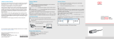
3.4 Software Window (Example)

Page 13
Getting Started
thermoIMAGER TIM Connect
1 IR image from the camera
2 Temperature profile: Shows the temperatures along max. 2 lines at any size and position in the image.
3 Control displays: Displays all temperature values in the defined measure areas like Cold Spots, Hot
Spots, temperature at cursor, internal temperature and chip temperature.
Alarm settings: Bar showing the defined temperature thresholds for low alarm value (blue arrow) and
high alarm value (red arrow). The color of numbers within control displays changes to red (when
temp. above the high alarm value) and to blue (when temp. below the low alarm value).
4 Temperature of measure area: Analyses the temperature according to the selected shape, e.g. aver-
age temperature of the rectangle. The value is shown inside the
IR image and the control displays.
5 Reference bar: Shows the scaling of temperature within the color palette.
6 Temperature time diagram: Shows the temperature curves over time for selectable region of interest
(ROI)
7 Histogram: Shows the statistic distribution of single temperature values.
8
Automatic / manual scaling of the palette (displayed temperature range): Man., </> (min, max), 1 s: 1
Sigma, 3 s: 3 Sigma, OPT: Palette optimization
9 Distance function: Adjustment of the motor focus to focus the IR picture (only thermoMETER TIM 8/
thermoIMAGER TIM 40)
10 Menu and Toolbar (Icons)
11 Icon enabling switching between color palettes
12 Status bar: Model and serial number, optic, temperature range, cursor position, device framerate/
display framerate, emissivity, ambient temperature, flag status
Under View and User Mode you can select between two additional display options. In addition to the Desk-
top view, the Touch view or the Tablet view can also be used here, see Fig. 1.
These additional views are particularly useful when using a touch computer or a tablet. The screen and menu
are customized and displayed according to their functions.

Page 14
Getting Started
thermoIMAGER TIM Connect
Fig. 1 Screen View - User Mode
Fig. 2 User Mode Touch Fig. 3 User Mode Tablet

Page 15
Getting Started
thermoIMAGER TIM Connect
Fig. 4 Configuration window for User Touch and Tablet
i
The User Mode Tablet provides only limited functionality.

Page 16
Getting Started
thermoIMAGER TIM Connect
3.5 Menu and Toolbar (Icons)
3.5.1 Menu
Using the menu you can adjust all software settings. Each feature will be explained in detail in the following
chapters of this manual:
Fig. 5 Menu bar
File Open, save and replay of files; recording; saving temp./time diagram data; snapshot;
screenshot; capture screen
Edit Editing of sequences and layouts
View Display or fade-out of different software features
Devices Choice of camera and self-referencing
Tools Additional settings of camera and software parameters as line scanner mode; layouts;
language; extended settings as merged device configuration and updating the firmware
Help Information about software; documentation; SDK; locking application

Page 17
Getting Started
thermoIMAGER TIM Connect
3.5.2 Toolbar (Icons)
The most important features of the software can be activated directly via the toolbar. You can redesign the toolbar according to your
preferences, see 4.2.2. Available toolbar icons are the following:
Open Visible video Previous palette
Save 3D Chart Configuration
Play Temperature profile
(horizontal)
Enable linescanning
Pause Temperature profile
(vertical)
Linescanner view
Sighting view
Stop Temperature time diagram Linescanner configuration
Record Digital display group Image subtraction
Save snapshot to file Snapshot history Image subtraction from file
Copy snapshot to clipboard Distance Refresh Flag
Save screenshot to file Toggle user mode Acknowledge Alarm
Screenshot to clipboard Full screen Close all tools
Reference bar IR/Visible Fusion Digital display
(main measure area)
Histogram Next palette Digital display
(mouse cursor)
Toggle Minimum, Mean Value,
Maximum
Exit Info
Config merged device
Fig. 6 Tool bar

Page 18
Software Configuration
thermoIMAGER TIM Connect
4. Software Configuration
4.1 General Settings
You can activate all here mentioned features in the Tools, Configuration and General menu (except for
color palettes).
4.1.1 Color Palettes
In the Tools, Configuration, Measuring colors and Standard palette menu you can choose from
a list of color palettes to achieve ideal displaying of the infrared image and the included temperature informa-
tion.
Fig. 7 Icons for color palette selection Fig. 8 Dropdown menu Standard palette
In the Tools, Configuration, Measuring colors and Standard palette menu, see Fig. 8, you can
choose from a list of color palettes to achieve ideal displaying of the infrared image and the included tem-
perature information.
You can also adjust the color palette via the icon on the toolbar or the menu View and Shift palette.

Page 19
Software Configuration
thermoIMAGER TIM Connect
Available color palettes
Iron Gray (Black = Cold)
Iron Hi Gray (White = Cold)
Rainbow Alarm Red
Rainbow Hi Alarm Green
Rainbow Medical Alarm Blue
Fig. 9 Palette selection
Blue Hi

Page 20
Software Configuration
thermoIMAGER TIM Connect
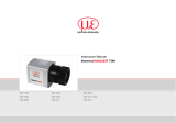
Palette Iron Palette Rainbow Palette Blue Hi
Palette Rainbow Hi Palette Rainbow Hi Palette Gray (Black = Cold)
Fig. 10 Examples of various color palettes
/