Page is loading ...

MICRO-EPSILON MESSTECHNIK GmbH & Co. KG
Koenigbacher Str. 15 · 94496 Ortenburg / Germany
Tel. +49 (0) 8542 / 168-0 · Fax +49 (0) 8542 / 168-90
[email protected] · www.micro-epsilon.com
Your local contact: www.micro-epsilon.com/contact/worldwide/
Operating Instructions
thermoIMAGER TIM NetPCQ

MICRO-EPSILON
MESSTECHNIK
GmbH & Co. KG
Koenigbacher Str. 15
94496 Ortenburg / Germany
Tel. +49 (0) 8542 / 168-0
Fax +49 (0) 8542 / 168-90
e-mail [email protected]
www.micro-epsilon.com
Mini Industrial PC for TIM series

thermoIMAGER NetPCQ
Contents
1. Safety ........................................................................................................................................................ 5
1.1 Symbols Used ................................................................................................................................................. 5
1.2 Warnings .......................................................................................................................................................... 5
1.3 Notes on CE Marking ...................................................................................................................................... 6
1.4 Intended Use ................................................................................................................................................... 6
1.5 Proper Environment ......................................................................................................................................... 6
2. Technical Data ........................................................................................................................................... 7
2.1 Functional Principle ......................................................................................................................................... 7
2.2 General Specifications ..................................................................................................................................... 7
2.3 Electrical Specifications ................................................................................................................................... 8
3. Delivery ..................................................................................................................................................... 8
3.1 Unpacking, Included in Delivery...................................................................................................................... 8
3.2 Storage ............................................................................................................................................................ 8
4. Mounting and Installation......................................................................................................................... 9
5. Control Elements and Connections ....................................................................................................... 10
6. Operation ................................................................................................................................................ 11
6.1 Operation Modes ........................................................................................................................................... 11
6.2 Remote Access to the thermoIMAGER TIM NetPCQ .................................................................................... 11
6.3 Applications and Start Options ...................................................................................................................... 14
6.3.1 NetBox Control Center ................................................................................................................ 15
6.3.1.1 Select Tab .................................................................................................................... 15
6.3.1.2 Log Tool Tab ................................................................................................................ 17
6.3.1.3 Imager Net Server ....................................................................................................... 19
6.4 File Transfer between thermoIMAGER TIM NetPCQ and PC ........................................................................ 20
6.5 Direct Ethernet Communication .................................................................................................................... 21
6.6 Connection to the thermoIMAGER TIM NetPC ............................................................................................ 22
6.7 Ethernet Network Communication ................................................................................................................ 27

thermoIMAGER NetPCQ
6.8 Stand-alone Operation .................................................................................................................................. 31
6.9 Write Protection Filter .................................................................................................................................... 32
6.10 System Recovery ........................................................................................................................................... 37
7. Instructions for Operation ...................................................................................................................... 44
7.1 Cleaning ......................................................................................................................................................... 44
8. Liability for Material Defects .................................................................................................................. 44
9. Service, Repair ....................................................................................................................................... 45
10. Decommissioning, Disposal .................................................................................................................. 45

Page 5
Safety
thermoIMAGER NetPCQ
1. Safety
System operation assumes knowledge of the operating instructions.
1.1 Symbols Used
The following symbols are used in these operating instructions:
Indicates a hazardous situation which, if not avoided, may result in minor or moder-
ate injury.
Indicates a situation which, if not avoided, may lead to property damage
Indicates a user action.
i
Indicates a tip for users.
Measure
Indicates hardware or a software button/menu.
1.2 Warnings
Connect the power supply and the display/output device according to the safety regulations for electrical
equipment.
> Risk of injury
> Damage to or destruction of the PC
Avoid shocks and impacts to the PC.
> Damage to or destruction of the PC
The supply voltage must not exceed the specified limits.
> Damage to or destruction of the PC
Avoid static electricity and keep away from very strong EMF (electromagnetic fields) e.g. arc welders or
induction heaters.
> Damage to or destruction of the PC

Page 6
Safety
thermoIMAGER NetPCQ
1.3 Notes on CE Marking
The following apply to the thermoIMAGER NetPCQ:
- EU Directive 2014/30/EU
- EU Directive 2014/35/EU
- EU Directive 2011/65/EU, “RoHS” category 11
Products which carry the CE mark satisfy the requirements of the EU directives cited and the relevant ap-
plicable harmonized standards (EN). The measuring system is designed for use in industrial and laboratory
applications.
The EU Declaration of Conformity is available to the responsible authorities according to EU Directive, article
10.
1.4 Intended Use
- The thermoIMAGER NetPCQ is designed for use in industrial and laboratory applications and is a fanless,
passively cooled, industrial PC.
- The system must only be operated within the limits specified in the technical data, see 2.
- The system must be used in such a way that no persons are endangered or machines and other material
goods are damaged in the event of malfunction or total failure of the system.
- Take additional precautions for safety and damage prevention in case of safety-related applications.
1.5 Proper Environment
- Protection class: IP30
- Ambient temperature: 0 ... +50 °C (+32 ... +122 °F)
- Storage temperature: -20 ... +75 °C (-4 ... +167 °F)
- Humidity: 10 ... 95 %, non-condensing

Page 7
Technical Data
thermoIMAGER NetPCQ
2. Technical Data
2.1 Functional Principle
The thermoIMAGER TIM NetPCQ is a miniaturized industry PC which expands the TIM series to a stand-
alone solution or which works as a USB to Ethernet converter. This mode enables larger possible distances
between process (IR camera) and process control (PC).
The thermoIMAGER NetPCQ includes a Windows 10 operating system that allows the user to install addition-
al software. The housing of the thermoIMAGER NetPC is made of anodized aluminum.
2.2 General Specifications
Model NetPC
Storage temperature -20 ... +75 °C (-4 ... +167 °F)
Ambient temperature 0 ... +50 °C (+32 ... +122 °F)
Relative humidity 10 ... 95 %, non-condensing
Material (housing) Anodized aluminum
Dimensions 117.5 mm x 165 mm x 64.5 mm (L x B x H)
Weight 1000 g
Vibration IEC 68-2-6: 3 G, 11 - 200 Hz, any axis
Shock IEC 68-2-27: 50 G, 11 ms, any axis
Operating system Windows 10

Page 8
Delivery
thermoIMAGER NetPCQ
2.3 Electrical Specifications
Model NetPCQ
Power supply 12 ... 24 VDC
Power consumption 10 W (+additional 2.5 W for IR camera)
Cooling passive
Processor Intel Atrom J1900 Quad Core CPU, 2 GHz
Hard disc 64 GB SSD
RAM 2 GB (DDR2, 533 MHz)
Ports 3 x USB 2.0
1 x USB 3.0
2 x RS232
VGA
Ethernet (Gigabit Ethernet)
Additional functions Status LED
3. Delivery
3.1 Unpacking, Included in Delivery
1 TIM NetPCQ inclusive SSD (64 GB)
1 USB Recovery stick including operating manual
Carefully remove the components of the measuring system from the packaging and ensure that the
goods are forwarded in such a way that no damage can occur.
Check the delivery for completeness and shipping damage immediately after unpacking.
If there is damage or parts are missing, immediately contact the manufacturer or supplier.
3.2 Storage
- Storage temperature: -20 ... +75 °C (-4 ... +167 °F)
- Humidity: 10 ... 95 %, non-condensing

Page 9
Mounting and Installation
thermoIMAGER NetPCQ
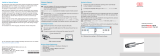
4. Mounting and Installation
The thermoIMAGER TIM NetPCQ can be mounted easily on a DIN rail (TS35) according EN50022 using the
rail mount adapter on the backside of the box.
Fig. 1 Dimensional drawing thermoIMAGER TIM NetPCQ, dimensions in mm, not to scale

Page 10
Control Elements and Connections
thermoIMAGER NetPCQ
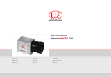
5. Control Elements and Connections
4
2
6
3
5
1
1 RS 232 Interface connections (two)
2 USB 2.0 connections (two)
3 DC power supply with power LED
4 VGA connection
5 1 x USB 3.0 and 1 x USB 2.0 connections
6 Ethernet connection

Page 11
Operation
thermoIMAGER NetPCQ
6. Operation
6.1 Operation Modes
The thermoIMAGER NetPCQ can be used in three different operation modes:
1. Converter USB – Ethernet with direct connection to a PC (point-to-point connection)
2. Converter USB – Ethernet with connection of a PC via a network or via the internet
3. Stand-alone operation with an IR camera
For powering the thermoIMAGER NetPCQ you can use any suitable industrial power supply with a voltage
output between 12 VDC and 24 VDC, see 2.3.
6.2 Remote Access to the thermoIMAGER TIM NetPCQ
For settings on the thermoIMAGER TIM NetPCQ you can connect a keyboard and a mouse to the available
USB sockets as well as a monitor to the VGA socket, see 6.8.
Another very simple option is remote control software, for example Remote Desktop (RDP) from Windows
or Ultra VNC with NetBox Utility, which is already included on the TIM Connect software CD provided with
thermoIMAGER TIM.
After installation you can have access to the thermoIMAGER TIM NetPCQ either from a PC directly connected
over an Ethernet cable or from a PC which is located anywhere and connected to the same network. Also
remote connection via the internet is possible.
To install NetBox Utility on your PC, please start install.bat in the /NetBox Utility directory on
the thermoIMAGER TIM Connect USB flash drive.
In addition to the utility software, the UltraVNC viewer will also be installed.
This program is available Start/Programs/NetBox-UltraVNC.
Before starting the NetBox Utility on your PC, please follow the instructions for specifying a fixed IP ad-
dress, see 6.6.

Page 12
Operation
thermoIMAGER NetPCQ
Next, please start the NetBox Utility program:
Fig. 2 View: Netbox Utility program start screen
Select the desired network adapter.
Remove the check mark from Filter by Network Name and click the Scan button.
The utility program now searches for NetPCQs that are in the network or are directly connected to your PC.
The devices found are shown in the Results window.
Mark the desired address in the Results window and click the Start Viewer > > button.

Page 13
Operation
thermoIMAGER NetPCQ
You should now see the thermoIMAGER TIM NetPCQ screen.
Fig. 3 View: thermoIMAGER TIM NetPCQ start screen

Page 14
Operation
thermoIMAGER NetPCQ
6.3 Applications and Start Options
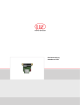
On the Desktop of the thermoIMAGER TIM NetPCQ you will find the following short cuts:
- TIM Connect
- Netbox Control Center
Fig. 4 Netbox Control Center shortcut
The Netbox Control Center allows for easy configuration of the NetPCQ.

Page 15
Operation
thermoIMAGER NetPCQ
6.3.1 NetBox Control Center
6.3.1.1 Select Tab
The Select tab lets you select programs that start automatically after powering on the NetPCQ.
Fig. 5 Netbox Control Center - Select selection
Under Application, you can select TIM Connect, Imager Net Server or Custom Application.
Application NetPC operating mode
TIM Connect Stand alone operation
Imager Net Server Converter operation USB-Ethernet
Custom Application Using the NetPCQ with another software
The start options set in the Control Center are automatically saved on the NetPCQ and are also available after
restarting.

Page 16
Operation
thermoIMAGER NetPCQ
Under Arguments, you can specify command line parameters (e.g., a special layout with which the TIM
Connect Software starts automatically).
Enable Autostart to have the selected application start automatically after the NetPCQ is started.
If for some reason the application no longer works properly (e.g., if the software has crashed), the Netbox
Control Center automatically restarts it, if Autostart has been set (software watchdog).

Page 17
Operation
thermoIMAGER NetPCQ
6.3.1.2 Log Tool Tab
The Log Tool tab provides the following information:
Application NetPC operating mode
Software Restarts Number of software restarts performed
Reason for last hardware restart Reason for the most recent restart of the NetPCQ
Software is not responding for Timer, which starts when the software does not respond and triggers a
restart of the selected application.
Actual runtime Current runtime of the software
Previous runtime Previous runtime of the software
Device Frequency Camera image frequency
Process Frequency Displayed image frequency
Net Transfer Frequency Image frequency transferred via the network (for Imager Net Server)
Fig. 6 Netbox Control Center - Log Tool selection

Page 18
Operation
thermoIMAGER NetPCQ
If an thermoIMAGER TIM is connected to the thermoIMAGER TIM NetPCQ, you should see two active appli-
cations: Log Tool and Imager Net Server, see Fig. 7, similarly Log Tool and TIM Connect, see Fig.
8.
Fig. 7 View NetPCQ - Log Tool and Imager Net
Server
Fig. 8 View NetPCQ - Log Tool and TIM Connect

Page 19
Operation
thermoIMAGER NetPCQ
6.3.1.3 Imager Net Server
Imager Net Server, see Fig. 7
Menu File Exit of the program
Devices Shows the connected thermoIMAGERS TIM
Flag Manual operation of the camera flag
USB video device Serial number of the connected imager device
T (C, F, B) Device temperatures (*C) C: FPA-Chip
F: Flag temperature
B: Housing temperature
PIFin (A, D) Status of the PIF input A: Analog IN (AI)
D: Digital IN (DI)
HW Cnt. Hardware-Counter (frame counter)
ADU (192, 144) ADU value of the center TIMxel (e.g. 192, 144 at TIM4xx)
Freq (D, P, N) Frequency (Hz): D: Device/ P: Processing/ N: Network
Time Time per single frame
Queue Number of frames in network queue
FOV, TR Field of view (horizontal) of the imager lens, temperature range
Fig. 9 Information in the Imager Net Server - application window

Page 20
Operation
thermoIMAGER NetPCQ
6.4 File Transfer between thermoIMAGER TIM NetPCQ and PC
To exchange files between the thermoIMAGER TIM NetPCQ and a directly connected or in the network
located PC please move the cursor to the title bar of the UltraVNC Viewer window and press the right
mouse button.
Start File Transfer.
Alternatively you can also press the following button in the tool bar:
In the following explorer window, see Fig. 10, you see on the left side your local PC (LOCAL MACHINE) and
on the right side the thermoIMAGER TIM NetPCQ (REMOTE MACHINE).
Now you can copy files between both computers via the network link by marking them and pressing
Send or Receive.
Fig. 10 File transfer view
/