Addonics Technologies R14HPCCES User manual
- Category
- Disk arrays
- Type
- User manual

www.addonics.com
Technical Support
If you need any assistance to get your unit functioning properly, please have your
product information ready and contact Addonics Technical Support at:
Hours: 8:30 am - 6:00 pm PST
Phone: 408-453-6212
Email: http://www.addonics.com/support/query/
v6.1.11
T E C H N O L O G I E S
User Guide
1U RAID Rack with HPM,
AES 256-bit encryption
(R14HPCCES)

www.addonics.com Technical Support (M-F 8:30am - 6:00pm PST) Phone: 408-453-6212 Email: www.addonics.com/support/query/
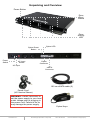
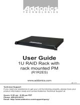
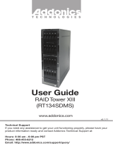
Unpacking and Overview
WARNING: Please remember to
set the power supply to your local
outlet voltage prior to plugging in
the power cord. Failure to do so
may damage the power supply.
Power Cord
(US Version Shown)
100 cm eSATA cable (2)
Power Button
Drive
Eject
Levers
Drive
Activity
LED
Power
Switch
AC Input
AC Input
Switch
Cipher
Connector
eSATA
Connector
Cipher LED
Cipher Reset
Button
Cipher Keys

www.addonics.com Technical Support (M-F 8:30am - 6:00pm PST) Phone: 408-453-6212 Email: www.addonics.com/support/query/
Cipher Chain Module
The Cipher hardware in the R14CCES is activated by either powering up the
unit or pressing the Cipher Reset button with the Cipher Key inserted. Without
activating the Cipher hardware, no drives in the Raid Rack will be visible to the
computer. Once the Cipher hardware is activated, the amber Cipher LED will
glow and the drives will be available, and the Cipher key may be removed. If
the Raid Rack is powered down or the Cipher Reset button is pressed, the key
will need to be reinserted and the Raid Rack powered up or the reset button
pressed while the key is inserted for the unit to resume normal operation. All
I/O operations are encrypted so drives must be partitioned and formatted as if
they were blank once installed in the Raid Rack. Should a drive with encrypted
data be removed from the Raid Rack and installed elsewhere, it will appear to
be completely blank with no partition table or file system.
Port Multiplier Compatibility
The R14HPCCES unit only supports configuring the drives in RAID configura-
tion. For JBOD installations, the R14CCES unit is recommended instead.
When configured as RAID, the controller is not required to support port
multipliers.
Using identical drives for all settings other than JBOD or LARGE is strongly
recommended. Creating a LARGE array using drives that have different
properties will use all space on all members, and performance will match that
of the member in use during any particular I/O operation. Creating a RAID
using drives that are not all the same size will result in all members using only
as much space as the smallest member. Creating a RAID using drives that
have different performance will degrade the overall performance of the array.
Hot Swapping drives
The R14HPCCES unit supports hot swapping (inserting or removing drives
while the drives are running and connected to a computer). The eSATA
controller on the computer must also support hot swapping - be sure to
confirm this before attempting to insert or remove drives while the system is
running. Also be sure to practice the appropriate safe removal procedure
before proceeding. Failure to practice safe removal procedures will result in
loss or corruption of data.

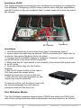
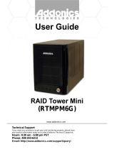
Installation (RAID)
The Cipher hardware prevents the use of software to configure or manage the
Port Multiplier. Configuring a RAID mode must be done using the dipswitches
and SET button on the port multiplier itself, located inside the unit at the rear of
the chassis.
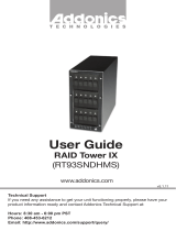
Installation
1. Use the provided key to unlock the front door if needed and open it.
2. Insert a drive into each bay as desired, SATA connectors first, label side up
as shown, then press the drive firmly into place.
3. Connect the Host eSATA cable to a computer. If desired, connect an exter-
nal eSATA drive to the Drive eSATA connector.
4. Make sure the AC input switch is set correctly, then connect the power cord
to an AC outlet.
5. Insert the Cipher Key into the Cipher
Keyhole.
6. Set the AC power switch on the rear to
ON, then press the power button
behind the front door to turn on the unit.
7. After the unit has been powered up, the
Cipher Key may be removed.
To remove a drive, pull the Eject Lever until
the drive disengages from the internal
connector then pull the drive out.
Port Multiplier Modes
The Port Multiplier supports several types of RAID and some non-RAID drive
sets. Each configuration has different properties and requirements, as follows:
www.addonics.com Technical Support (M-F 8:30am - 6:00pm PST) Phone: 408-453-6212 Email: www.addonics.com/support/query/
Dipswitch
SET Button

JBOD Mode (Individual Drives)
Number of drives: at least 1
Unit capacity: N/A (100% of each individual drive)
Spares: no
Fault tolerance: none
JBOD mode offers all connected units to the host adapter, no RAID is defined at
all.
NOTE: JBOD mode is not supported on the R14HPCCES.
RAID 0 (Stripe set)
Number of drives: at least 2
Unit capacity: size of each member times number of members.
Spares: no
Fault tolerance: none - if any member is lost all data is lost.
RAID 0 “stripes” the file system across the array by placing “chunks” of data
sequentially between drives in a specific order.
RAID 1 or 10 (Mirror set, Stripe of mirror sets)
Number of drives: 2 (RAID 1) or 4 (RAID 10).
Unit capacity: size of one member (RAID 1) or size of two members (RAID 10).
Spares: yes – if EZ mode is not disabled and 3 (RAID 1) or 5 (RAID 10) drives
are present, the array will be initialized with a spare.
Fault tolerance: RAID 1 can withstand the loss of one drive without losing data.
RAID 10 can withstand the loss of one drive from each mirror set without losing
data.
RAID 1 works by duplicating the exact same data on two drives.
RAID 10 works by using two RAID 1 sets configured as members of a RAID 0.
Disks 1 and 2 are mirrored, disks 3 and 4 are mirrored, and the two mirror sets
are striped together.
RAID 3 (Stripe set with dedicated parity)
Number of drives: at least 3
Unit capacity: size of one member times number of members minus one.
Spares: yes
Fault tolerance: can withstand the loss of one drive without losing data.
RAID 3 works by striping data for individual I/O blocks across all members
except one, which contains parity data for the stripe set computed internally by
the Port Multiplier. In the event of failure, the missing information can be calcu-
lated using the parity information.
www.addonics.com Technical Support (M-F 8:30am - 6:00pm PST) Phone: 408-453-6212 Email: www.addonics.com/support/query/

www.addonics.com Technical Support (M-F 8:30am - 6:00pm PST) Phone: 408-453-6212 Email: www.addonics.com/support/query/
RAID 5 (Stripe set with striped parity)
Number of drives: at least 3
Unit capacity: size of one member times number of members minus one.
Spares: yes
Fault tolerance: can withstand the loss of one drive without losing data.
RAID 5 works by striping entire I/O blocks across all members of the set, with
each member taking turns carrying parity data computed by the Port Multi-
plier. In the event of failure, the missing information can be calculated using
the parity information.
CLONE (Mirror set)
Number of drives: at least 2
Unit capacity: size of one member.
Spares: yes
Fault tolerance: can withstand the loss of any number of drives without losing
data as long as at least one complete member remains online. CLONE mode
works the same way as RAID 1, by maintaining a complete copy of the entire
set of data on each drive.
LARGE (Spanned set)
Number of drives: at least 2
Unit capacity: 100% of all drives together regardless of differences in size
Spares: no
Fault tolerance: cannot withstand the loss of any drives without losing data.
However, some data may be recovered as long as the drive(s) carrying the
file system data (boot record, directory, etc.) remain online. LARGE mode is
neither a RAID nor is it a JBOD. It works by declaring the sum of all available
space of the member drives as a single unit, without striping the data. As
each member is filled, new data is stored on the next.
Notes about Spare Drives
If EZ mode is disabled (SW1:2 ON), all individual drives not configured as
array members will be offered to the host adapter as separate units.
To create an array with one or more spares, set or modify the RAID mode
while the spares are disconnected from the Port Multiplier. When EZ mode is
enabled (SW1:2 OFF), individual drives connected when an array is present
are considered spare. Spare drives must be equal to or larger in size than the
smallest member. When any type of array is defined, individual units will be
considered spare.
RAID 0 and LARGE arrays are not fault-tolerant and spare drives will not be
useful; therefore, disabling EZ for these arrays is recommended. When a
spare drive is present and a fault-tolerant RAID (1, 10, 3, or 5) is defined, EZ
mode will automatically rebuild any available spares into the array to replace
a failed member.

www.addonics.com Technical Support (M-F 8:30am - 6:00pm PST) Phone: 408-453-6212 Email: www.addonics.com/support/query/
Configuring the Port Multiplier Using Dipswitches
Resetting the RAID
NOTE: This procedure destroys all RAID data. It should not harm individual
drives or their contents; however, creating backups of all data is strongly recom-
mended before proceeding.
Be sure the port multiplier is connected to an active host before proceeding. The
port multiplier will not complete the process if it has no host connection.
1. Power down the unit using the AC power switch on the rear, then set the dip
switch to the desired RAID Mode.
2. While holding the SET button, turn the unit on. A long beep will sound from the
Port Multiplier. The SET button may be released once the long beep starts.
After releasing the SET button, turn on the drives by pressing the power button on
the front of the unit. Once the drives are ready, the port multiplier should “chirp” to
indicate the process is complete. If instead of a chirp the Port Multiplier sounds a
series of short beeps, an error has occurred during the process.
Setting or Modifying the RAID Mode
NOTE: Setting or modifying the RAID mode destroys all data.
Be sure the port multiplier is connected to an active host before proceeding. The
port multiplier will not complete the process if it has no host connection.
1. Follow the procedure for resetting the RAID Mode.
2. Power down the unit using the AC power switch on the rear, then set the dip
switch to the desired RAID Mode.
3. While holding the SET button, turn the unit on. A long beep will sound from the
Port Multiplier. The SET button may be released once the long beep starts.
After releasing the SET button, turn on the drives by pressing the power button on
the front of the unit. Once the drives are ready,, the port multiplier should “chirp”
to indicate the process is complete. If instead of a chirp the Port Multiplier sounds
a series of short beeps, an error has occurred during configuration of the array.
BZS Switch (SW1:1):
The BZS switch is used to silence the audible alarm buzzer. The OFF position
permits the audible alarm, and the ON position silences the audible alarm. The
BZS switch has immediate effect.
EZ Switch (SW1:2):
The EZ (spare) switch inhibits spares when ON. When in the OFF position, all
individual drives (not defined as members of an array) are considered spare and
are not offered to the operating system. Should a RAID become degraded, when
the EZ switch is in the OFF position a spare drive will be used automatically to
rebuild the RAID, if present. EZ mode is determined when the unit is powered up.
Changing the switch will have no effect until the unit has been re-powered.
Warning: turning off the EZ switch to rebuild an array will consider any drives not
declared array members to be eligible for rebuild as a spare. Rebuilding will
destroy all existing data on that drive and the drive chosen is not predictable.
Disconnect any individual drives with valuable data on them before enabling EZ
Mode.

www.addonics.com
Phone: 408-573-8580
Fax: 408-573-8588
Email: http://www.addonics.com/sales/query/
CONTACT US
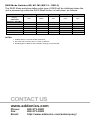
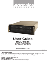
RAID Mode Switches M2, M1, M0 (SW1:3 – SW1-5)
The RAID Mode switches define what type of RAID will be initialized when the
unit is powered up while the RAID Mode button is held down, as follows:
NOTES:
1. Audible Alarm is recommended at all times.
2. EZ mode has no effect when no array is defined.
3. Disabling EZ for RAID 0 and LARGE is strongly recommended.
Dipswitch Position
1 (BZS)
1
2 (EZ) 3 (M2) 4 (M1) 5 (M0)
JBOD (Individual
Drives)
* FACTORY
DEFAULT SETTING
OFF
OFF
2
OFF OFF OFF
RAID 0 OFF
ON
3
ON ON ON
RAID 1 OR 10 OFF OFF ON ON OFF
RAID 3 OFF OFF ON OFF OFF
RAID 5 OFF OFF OFF ON OFF
CLONE OFF OFF OFF ON ON
LARGE OFF ON ON OFF ON
-
 1
1
-
 2
2
-
 3
3
-
 4
4
-
 5
5
-
 6
6
-
 7
7
-
 8
8


Addonics Technologies R14HPCCES User manual
- Category
- Disk arrays
- Type
- User manual
Ask a question and I''ll find the answer in the document
Finding information in a document is now easier with AI
Related papers
-
 Addonics Technologies ST9BDVES User manual
-
 Addonics Technologies R1R2ES User manual
-
 Addonics Technologies Computer Hardware RT93SNDHMS User manual
-
Addonics Technologies ST45HPMXA-B User manual
-
 Addonics Technologies RR2035RSDMS User manual
-
 Addonics Technologies RR2035ASDML User manual
-
 Addonics Technologies RTM2233EU3 User manual
-
 Addonics Technologies RAID Tower XIII RT134SDMS User manual
-
 Addonics Technologies RTMPM6G User manual
-
Addonics Technologies ADU3ESAM User manual


Other documents
-
Addonics Secure NAS R5 User guide
-
Addonics AD5SARPM-E Installation guide
-
Addonics AD5SAPM Installation guide
-
Addonics RAID Tower III User guide
-
Addonics RT93DAHXML User guide
-
-
-
bolid BZS User manual
-
-