Page is loading ...
Before attempting to connect or operate this product,
please read these instructions carefully and save this manual for future use.
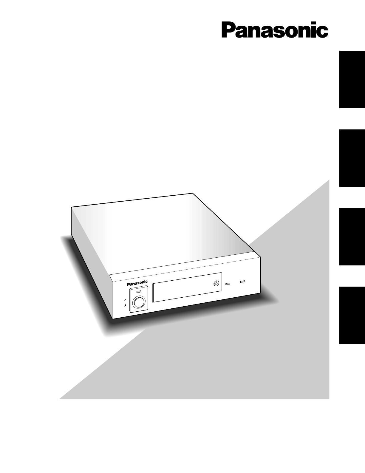
Model No. WJ-MP204
Data Multiplex Unit
Operating Instructions
P
O
W
E
R
O
N
O
F
F
A
LA
R
M
A
LA
R
M
S
U
S
P
E
N
D
Data Multiplex Unit W
J-M
P204
ENGLISH
DEUTSCH
FRANÇAIS
ESPAÑOL
2
ENGLISH VERSION
The serial number of this product may be found on the bot-
tom of the unit.
You should note the serial number of this unit in the space
provided and retain this book as a permanent record of your
purchase to aid identification in the event of theft.
Model No. WJ-MP204
Serial No.
The lightning flash with arrowhead symbol,
within an equilateral triangle, is interned to
alert the user to the presence of uninsulated
"dangerous voltage" within the product's
enclosure that may be of sufficient magni-
tude to constitute a risk of electric shock to
persons.
The exclamation point within an equilateral
triangle is intended to alert the user to the
presence of important operating and mainte-
nance (servicing) instructions in the litera-
ture accompanying the appliance.
CAUTION:
Before attempting to connect or operate this product,
please read the label on the bottom.
Wij verklaren als enige aansprakelijke, dat het product waarop deze
verklaring betrekking heeft, voldoet aan de volgende normen of andere
normatieve documenten, overeenkomstig de bepalingen van Richtlijnen
73/23/EEC en 89/336/EEC.
Vi erklærer os eneansvarlige for, at dette produkt, som denne deklara-
tion omhandler, er i overensstemmelse med standarder eller andre nor-
mative dokumenter i følge bestemmelserne i direktivene 73/23/EEC og
89/336/EEC.
Vi deklarerar härmed värt fulla ansvar för att den produkt till vilken
denna deklaration hänvisar är i överensstämmelse med standarddoku-
ment, eller andra normativa dokument som framställs i EEC-direktiv nr.
73/23 och 89/336.
Ilmoitamme yksinomaisella vastuullamme, että tuote, jota tämä ilmoitus
koskee, noudattaa seuraavia standardeja tai muita ohjeellisia asiakirjoja,
jotka noudattavat direktiivien 73/23/EEC ja 89/336/EE. säädöksiä.
Vi erklærer oss alene ansvarlige for at produktet som denne erklæringen
gjelder for, er i overensstemmelse med følgende normer eller andre nor-
mgivende dokumenter som følger bestemmelsene i direktivene
73/23/EEC og 89/336/EEC.
We declare under our sole responsibility that the product to which this
declaration relates is in conformity with the standards or other normative
documents following the provisions of Directives EEC/73/23 and
EEC/89/336.
Noi dichiariamo sotto nostra esclusiva responsabilità che il prodotto a
cui si riferisce la presente dichiarazione risulta conforme ai seguenti
standard o altri documenti normativi conformi alle disposizioni delle
direttive CEE/73/23 e CEE/89/336.
FOR YOUR SAFETY PLEASE READ THE FOLLOWING TEXT CARE-
FULLY.
This appliance is supplied with a moulded three pin mains plug for your
safety and convenience.
A 13 amp fuse is fitted in this plug.
Should the fuse need to be replaced please ensure that the replacement
fuse has a rating of 13 amp and that it is approved by ASTA or BSI to
BS1362.
Check for the ASTA mark
H or the BSI mark G on the body of the
fuse.
If the plug contains a removable fuse cover you must ensure that it is
refitted when the fuse is replaced.
If you lose the fuse cover the plug must not be used until a replacement
cover is obtained.
A replacement fuse cover can be purchased from your local Panasonic
Dealer.
IF THE FITTED MOULDED PLUG IS UNSUITABLE FOR THE SOCK-
ET OUTLET IN YOUR HOME THEN THE FUSE SHOULD BE
REMOVED AND THE PLUG CUT OFF AND DISPOSED OF SAFELY.
THERE IS A DANGER OF SEVERE ELECTRICAL SHOCK IF THE
CUT OFF PLUG IS INSERTED INTO ANY 13 AMP SOCKET.
If a new plug is to be fitted please observe the wiring code as shown
below.
If in any doubt please consult a qualified electrician.
WARNING: This apparatus must be earthed.
IMPORTANT
The wires in this mains lead are coloured in accordance with the follow-
ing code.
Green-and-yellow: Earth
Blue: Neutral
Brown: Live
As the colours of the wire in the mains lead of this appliance may not
correspond with the coloured markings identifying the terminals in your
plug, proceed as follows.
The wire which is coloured green-and-yellow must be connected to
the terminal in the plug which is marked with the letter E or by the earth
symbol
I or coloured green or green-and-yellow.
The wire which is coloured blue must be connected to the terminal in
the plug which is marked with the let-
ter N or coloured black.
The wire which is coloured brown
must be connected to the terminal in
the plug which is marked with the let-
ter L or coloured red.
How to replace the fuse
Open the fuse compartment with
a screwdriver and replace the fuse
and fuse cover.
For U.K.
CAUTION: TO REDUCE THE RISK OF ELECTRIC SHOCK,
DO NOT REMOVE COVER (OR BACK).
NO USER-SERVICEABLE PARTS INSIDE.
REFER SERVICING TO QUALIFIED SERVICE PERSONNEL.
CAUTION
RISK OF ELECTRIC SHOCK
DO NOT OPEN
WARNING:
To reduce the risk of fire or electric shock, do not expose this appliance to rain or moisture.

3
CONTENTS
PREFACE .................................................................................................................................................................................... 4
FEATURES .................................................................................................................................................................................. 4
COMMUNICATION MODE .......................................................................................................................................................... 5
PRECAUTIONS ........................................................................................................................................................................... 5
MAJOR OPERATING CONTOROLS AND THEIR FUNCTIONS. ................................................................................................. 6
■ Front View ........................................................................................................................................................................... 6
■ Rear View ............................................................................................................................................................................ 7
SETUP PROCEDURE .................................................................................................................................................................. 8
DIP SWITCH SETTING ................................................................................................................................................................ 9
■ Setting Communication Mode ............................................................................................................................................ 9
■ Setting the Communication Mode via RS-485 or Data Port ............................................................................................... 9
■ Setting the VS or VD Signal Output .................................................................................................................................... 9
SETTING ADDRESSES ............................................................................................................................................................. 10
■ Panasonic Security Data Mode ......................................................................................................................................... 10
■ Camera Communication Mode ......................................................................................................................................... 10
SETUP MENU ............................................................................................................................................................................. 11
■ Setup Menu ....................................................................................................................................................................... 11
■ Displaying the Setup Menu for Panasonic Security Data Mode ....................................................................................... 12
■ Communication Setup of Panasonic Security Data Mode ................................................................................................ 12
■ System Setup for Panasonic Security Data Mode.............................................................................................................. 13
■ Displaying the Setup Menu of Camera Communication Mode ......................................................................................... 16
■ Communication Setup for Camera Communication Mode ................................................................................................ 16
■ System Setup for Camera Communication Mode.............................................................................................................. 18
INSTALLATION .......................................................................................................................................................................... 20
■ Mounting in the Rack ......................................................................................................................................................... 20
SYSTEM CONNECTION ............................................................................................................................................................. 21
■ Basic System Connection ................................................................................................................................................. 21
■ Alarm/Remote Connector .................................................................................................................................................. 24
■ Connector Selection for Setup Menu Output .................................................................................................................... 25
■ RS485 Terminal ................................................................................................................................................................. 25
■ Connection to WV-CU360 ................................................................................................................................................. 26
OPERATING PROCEDURES ...................................................................................................................................................... 27
■ Controlling the Camera Functions with the Data Multiplex Unit WJ-MP204 ...................................................................... 27
■ Controlling the Camera Functions with the System Controller WV-CU360 ....................................................................... 27
■ Camera Selection .............................................................................................................................................................. 27
ALARM CONTROL FUNCTIONS ............................................................................................................................................... 28
■ Alarm Input ........................................................................................................................................................................ 28
■ Alarm Operation ................................................................................................................................................................ 28
■ Alarm Reset ....................................................................................................................................................................... 28
■ Alarm Suspend .................................................................................................................................................................. 28
SPECIFICATIONS ...................................................................................................................................................................... 29
STANDARD ACCESSORY ......................................................................................................................................................... 29
ALL RESET ................................................................................................................................................................................. 29
APPENDIX .................................................................................................................................................................................. 30
ENGLISH

4
PREFACE
FEATURES
The WJ-MP204 Data Multiplex Unit enables you to remote
control multiple surveillance cameras, check alarm set-
tings, operate the cameras and control other system com-
ponents when combined with the WV-CU360 System
Controller with Panasonic Security Data mode
capability.
The WJ-MP204 offers the following functions:
• Panasonic Security Data mode (with WV-CU360 con-
nected)
• Camera Communication mode (with WJ-SX350 con-
nected via RS-485)
• Camera channel selection
• Alarm resetting and suspension
• Communication and system setup
Remote control of the cameras using the WV-CU360
System Controller with Panasonic Security Data mode
capability, including:
• Camera settings
• Pan/Tilt Head and Camera Housing (Wiper, Defroster,
etc.)
• Motorized Zoom Lens (Focus, Zoom, Iris, etc.)
• Camera setup
Camera Spot function
Allows you to display on the monitor any camera image
selected on the WJ-MP204 Data Multiplex Unit or the WV-
CU360 System Controller.
Alarm function
Performs the following operations in response to alarm
input to the WJ-MP204 Data Multiplex Unit:
• Activates the camera preset function and displays the
image of the camera at the preset position on the moni-
tor.
• Outputs an alarm signal from the Alarm/Remote con-
nector to external devices to notify them of the alarm.
• Accepts alarm input multiplexed with video signal from
the camera.
Using up to four Data Multiplex Units in daisy-chain con-
nection allows expansion of the system to include up to 16
cameras. The distance between the system and the cam-
eras can be extended by connecting an AV Codec or simi-
lar device. The WJ-MP204 and other devices compatible
with Panasonic Security Data mode have the logo
.

5
PRECAUTIONS
• Refer all work related to the installation of this
product to qualified service personnel or system
installers.
• Do not block the ventilation opening or slots on the
cover.
To prevent the appliance temperature from rising, place
the appliance at least 5 cm (2 inches) away from the
wall.
• Do not drop metallic parts through slots.
This could permanently damage the appliance. Turn
the power off immediately and refer servicing to
qualified service personnel.
• Do not attempt to disassemble the appliance.
To prevent electric shock, do not remove screws or
covers.
There are no user-serviceable parts inside. Refer main-
tenance to qualified service personnel.
• Handle the appliance with care.
Do not strike or shake, as this may damage the appli-
ance.
• Do not expose the appliance to water or moisture,
nor try to operate it in wet areas.
Do take immediate action if the appliance becomes
wet. Turn the power off and refer servicing to qualified
service personnel. Moisture can damage the appliance
and also cause electric shock.
• Do not use strong or abrasive detergents when
cleaning the appliance body.
Use a dry cloth to clean the appliance when it is dirty.
When the dirt is hard to remove, use a mild detergent
and wipe gently.
• Do not operate the appliance beyond its specified
temperature, humidity or power source ratings.
Do not use the appliance in an extreme environment
where high temperature or high humidity exists.
Use the appliance at temperatures within –10°C -
+50°C (14°F - 122°F) and a humidity below 90 %.
The input power source for this appliance is 220 - 240 V
AC 50 Hz.
COMMUNICATION MODE
The WJ-MP204 Data Multiplex Unit can communicate with
the WV-CU360 System Controller in Panasonic Security
Data mode or Camera Communication mode. Both modes
require different settings.
Panasonic Security Data mode
This mode lets you
• Operate multiple cameras and devices via one WV-
CU360 System Controller.
• Connect up to 16 Data Multiplex Units for Panasonic
Security Data mode communication (up to 4 in case of
the WJ-MP204).
• Set a unit number for each Data Multiplex Unit.
• Synchronize each channel by multiplexing the video
signal with the sync signal VD2.
• Enable cable loss compensation.
• For Panasonic Security Data communication mode refer
to the following pages:
Setup Procedure ................................................... 8
Setting Communication Mode ............................... 9
Setting Addresses ............................................... 10
Setup Menu ......................................................... 11
Displaying the Setup Menu ................................. 12
Communication Setup ................................... 12, 13
System Setup ............................................ 13,14,15
Basic System Connections ................................. 21
Connecting Two or More Data Multiplex
Units to System Controller WV-CU360 ................ 22
Camera Communication mode
This mode lets you
• Extend the distance between the cameras and the WJ-
MP204 Data Multiplex Unit by RS-485 cables.
• Control multiple cameras installed at a distance of up
to 1 200 m (4 000 ft) from the Data Multiplex Unit by
connecting an AV codec.
• Set or change camera address from the Setup menu of
the Data Multiplex Unit.
• Synchronize each channel by multiplexing the video
signal with the sync signal VD2.
• Enable cable loss compensation.
* For Camera Communication mode refer to the following
pages:
Setup Procedure ................................................... 8
Setting Communication Mode ............................... 9
Setting Addresses ............................................... 10
Setup Menu ......................................................... 11
Displaying the Setup Menu ................................. 16
Communication Setup ................................... 16, 17
System Setup ................................................ 18, 19
Connecting Two or More Data Multiplex Units to
Matrix Switcher WJ-SX350................................... 23
6
MAJOR OPERATING CONTOROLS AND THEIR FUNCTIONS
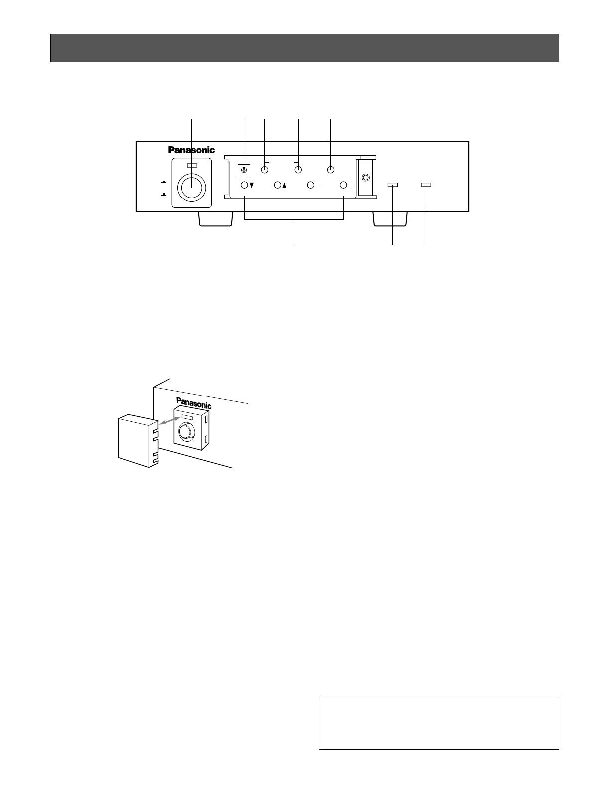
q Power Switch (POWER ON/OFF)
Press once to turn on the Data Multiplex Unit.
The switch remains down (;) and the LED lights up.
Press again to turn off the unit. The switch comes up
(l).
Note: To prevent that the power of the Data Multiplex
Unit is turned off accidentally, install the supplied
switch protector.
w Unit Switch (0 - 8) (UNIT)
Sets the addresses given below.
Turn the switch to align the desired number with the
arrow.
• Data Multiplex Unit address
• Camera addresses (for CAMERA IN 1 - 4)
Note: Keep the Power switch in the OFF position while
setting addresses.
e Alarm Reset Button (ALARM RESET)
This button resets the Active Alarm Mode. Pressing this
button goes off the Alarm indicator and replaces the
“Alarm” indication on the monitor screen.
r Alarm Suspend/Set Button (ALARM SUSPEND/SET)
• Pressing this button will suspend alarm input, alarm
input will be ignored. Pressing it again will reset the
function.
• In the Setup menu, opens submenus for more
detailed settings. Menu items having a submenu
are identified by a return symbol at the end of the
line.
t Setup/ESC Button (SETUP/ESC)
Pressing this button for 2 seconds or more opens the
Setup menu of the Data Multiplex Unit. If pressed for
less than 1 second, it functions as the Escape button
and returns you to the previous menu.
To close the Setup menu when the setup is completed,
press the button for 2 seconds or more.
Note: Make sure to distinguish between 1-second and
2-second operation of this button.
y Camera Selection Buttons
Select the camera for display of live picture. When the
Setup menu is displayed on the monitor, these buttons
function as follows.
Cursor button (C): Moves the cursor down.
Cursor button (D): Moves the cursor up.
Decrement button (–): Selects modes and parameters
in the Setup menu. When setting a numerical value
such as the camera number or address, pressing
this button will decrement the value.
Increment button (+): Selects modes and parameters
in the Setup menu. When setting a numerical value
such as the Camera number or address, pressing
this button will increment the value.
u Alarm Indicator (ALARM)
This indicator blinks when the alarm is activated. It
changes to steady light when the alarm is automatically
reset.
i Alarm Suspend Indicator (ALARM SUSPEND)
This indicator lights up while the alarm is suspended. It
goes off when the function is reset.
POWER
ON
OFF
ALARM
Data Multiplex Unit WJ-MP204
ALARM
SUSPEND
1234
ESCSET
RESET
SUSPEND SET UP
ALARM
UNIT
0
9
8
7
6
5
4
3
2
1
q w e r
y
u i
t
■ Front View
SWITCH
PROTECTOR
Note: To use the switch w and the buttons in e, r, t
and y above, remove the front cover by loosening
the screw with a screwdriver. For further informa-
tion, see page 27.

7
■ Rear View
o Camera Input Connectors 1-4 (CAMERA IN 1, 2, 3, 4)
These connectors accept the composite video signal
from the camera.
!0 Camera Output Connectors 1-4 (CAMERA OUT 1, 2,
3, 4)
The video signal connected to the Camera Input
Connector (CAMERA IN 1, 2, 3, 4) is looped through to
these connectors.
!1 Video Input Connector (SPOT IN)
Used when multiple Data Multiplex Units are connect-
ed.
Note: To connect multiplex Data Multiplex Units, set
DAISY MODE in the System menu to ON.
!2 Video Output Connector (SPOT OUT)
This connector supplies the video output signal for the
spot monitor. It is also used when connecting multiple
Data Multiplex Units.
!3 VS/VD Input Connector (VS/VD IN)
Accepts the video sync signal (VS), or a vertical drive
signal (VD) supplied by external devices to synchro-
nize the Data Multiplex Unit with other devices.
Notes:
• Connect a device supplying an external sync sig-
nal that complies with the CCIR specifications. Do
not input signals having a high jitter content such
as VTR playback signals.
• To input a vertical drive signal, set VS/VD INPUT in
the System menu to VD.
!4 VS/VD Output Connector (VS/VD OUT)
This connector is used to supply the sync signal input
to the VS/VD IN connector, or the internally generated
sync signal VD, to other devices.
Note:
• Set MODE Switch (1) to OFF (THROUGH) in sup-
plying the signals input to the VS/VD IN connector
to other devices.
• Set MODE Switch (1) to ON (VD) in supplying the
internally generated reference sync signal VD to
other devices.
!5 Alarm/Remote Connector (ALARM/REMOTE)
The factory default setting is ALARM input. For remote
input, set TERMINAL in the System menu to REMOTE.
Can also be used as ALARM/REMOTE output terminal
by moving an internal connector. Refer to page 24 for
details.
!6 RS485 Terminal (RS485)
This terminal is used to exchange control data with the
camera site via Camera Communication mode.
!7 Data Port (DATA)
This port is used to exchange control data with the WV-
CU360 System Controller in Panasonic Security Data
mode.
Note: Cannot use both RS485 Terminal and Data port
at the same time. It can be distributed correspond-
ing to the communication mode as follows:
Camera Communication Mode: Use only the RS485
terminal.
Panasonic Security Data mode: Use only the Data
port.
!8 Dip Switches (MODE)
These switches are used to select the mode.
!9 Signal Ground Terminal (SIGNAL GND)
@0 Power Cord
RT
IN IN
CAMERA RS485
ABABG
VS/VDSPOT DATA
ALARM / REMOTE
MODE
SIGNAL GND
4321
OUT OUT
IN
OUT
4321
o
!0
!2 !4
!6
!7 !8
!1 !3 !5 !9 @0

8
Follow the procedures below for setup.
1. Press the Power Switch back to the OFF position.
Check that the Power Switch LED is off.
SETUP PROCEDURE
2. Set the MODE Switches as follows:
Select an operation mode using the MODE Switches on
the rear panel. See page 9 for details.
• Communication mode
This mode must be selected whenever this data multi-
plexer unit is used.
• Set the following in communication using the DATA
Port or RS485 terminal. Termination ON or OFF, full
duplex or half duplex.
• Set the type of sync signal to be output from the Data
Multiplex Unit.
Set it in supplying the sync signal from the VS/VD OUT
connector to other devices.
3. Set the UNIT Switch.
Set address (unit address, or camera addresses) using
the UNIT Switch on the front panel. The addresses to
be set vary depending on the communication mode
set. See page 10 for details.
4. Press the Power Switch down to the ON position.
Check that the Power Switch LED lights up.
5. Set parameters on the Setup menu.
Set parameters on the Setup menu as required to use
the Data Multiplex Unit. The contents of the Setup
menu vary depending on the communication mode
used. See page 11 for details.
POWER
ON
OFF
Data M
1234
ESCSET
RESET
SUSPEND SET UP
ALARM
UNIT
0
9
8
7
6
5
4
3
2
1
Power Switch
Power Switch LED
9
Before connecting the Data Multiplex Unit, check how the
DIP switches are set on the rear panel in cases where the
system setup must be changed.
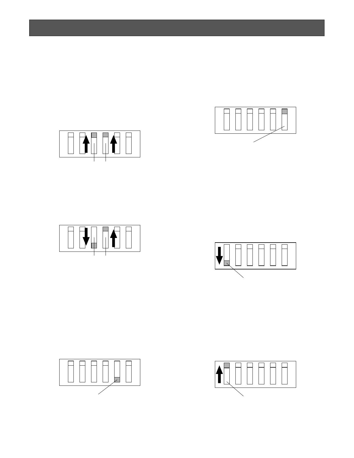
■ Setting Communication Mode
● Panasonic Security Data Mode
Check that Dip Switches SW3 and SW4 are up.
● Camera Communication Mode
Check that Dip Switch SW3 is down and Dip Switch
SW4 up.
■ Setting VS or VD Signal Output
● Supplying Video Drive Signal in Internal Sync
Mode*
Check that Dip Switch SW1 is down (VD).
DIP SWITCH SETTING
SW3
123456
SW4
SW1
VD
THROUGH
SW5
ON
OFF
SW6
2-LINE
4-LINE
SW3 SW4
123456
SW1
VD
THROUGH
* Synchronized vertical drive signal is supplied in case
of signal input to VS/VD IN connector.
● Supplying Synchronized Signal Input to VS/VD
IN Connector
Check that Dip Switch SW1 is up (THROUGH).
■ Setting the Communication
Mode via RS485 or Data Port
● Termination
Check that Dip Switch SW5 is down (ON).
Note: In case of using two Data Multiplex Units or
more, set Dip Switch SW5 on only one point at the
end position of the unit to the down position.
● Data Line Selection Mode
Set DIP Switch SW6 to the 4-LINE or 2-LINE position
according to the desired data line selection mode.
4-LINE: Full Duplex
2-LINE: Half Duplex
The initial factory setting is 4-LINE.
Note: Set SW6 to 4-LINE for communication in
Panasonic Security Data mode.
10
Address setting varies from one communication mode to another.
The setting should be made by qualified service personnel or system installers.
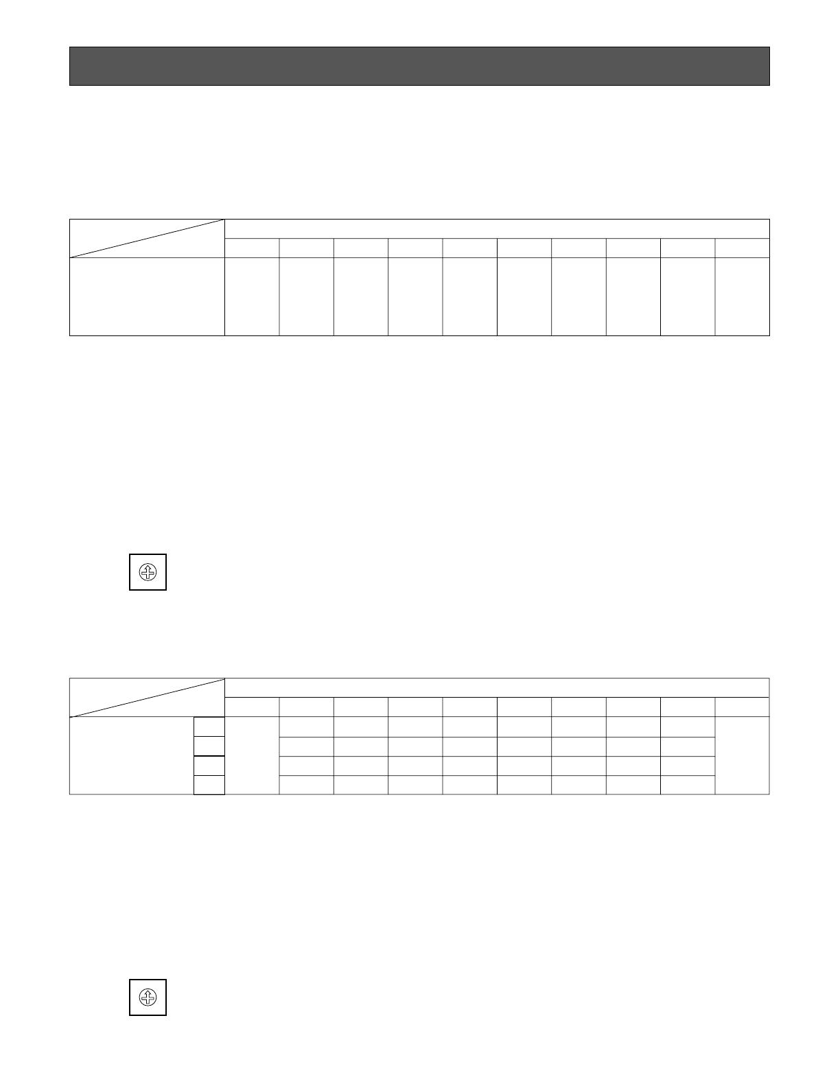
■ Panasonic Security Data Mode
Set each number as follows.
SETTING ADDRESSES
■ Camera Communication Mode
Set camera address as follows.
Notes:
• Do not set the UNIT switch to position 9 because it is a reserved number.
• When two Units corresponding to Panasonic Security Data or more are connected, check that each UNIT switch is set to a
number different from those of the others.
• In changing unit addresses using the setup menu, set the UNIT switch to position 0.
• Keep the power switch in the OFF position while setting unit numbers. Addresses cannot be set if power is on.
• For details of setting the System Controller WV-CU360, refer to the Operating Instruction for the System Controller.
Unit address
of WJ-MP204
UNIT Switch Settings of WJ-MP204
87654321
1
0
Set the
number in
Setup
menu
2345678
9
Prohibition
of a Setup
(reserved
number)
CAMERA
IN/OUT Connector
UNIT Switch Settings of WJ-MP204
8765432
1
1
2
3
4
0
Set the
number in
Setup
menu
1
2
3
4
5
6
7
8
9
10
11
12
13
14
15
16
17
18
19
20
21
22
23
24
25
26
27
28
29
30
31
32
9
Prohibition
of a Setup
(reserved
number)
Notes:
• Do not set the UNIT switch to position 9 because it is a reserved number.
• When two Units or more are connected, check that each UNIT switch is set to a number different from those of the others.
• In changing camera addresses using the setup menu, set the UNIT switch to position 0.
• Keep the power switch in the OFF position while setting unit numbers. Addresses cannot be set if power is on.
● Setting Unit Addresses
Turn the UNIT switch till the arrow points the desired number.
0
9
8
7
6
5
4
3
2
1
UNIT
● Setting Unit Addresses
Turn the UNIT switch till the arrow points the desired number.
0
9
8
7
6
5
4
3
2
1
UNIT
11
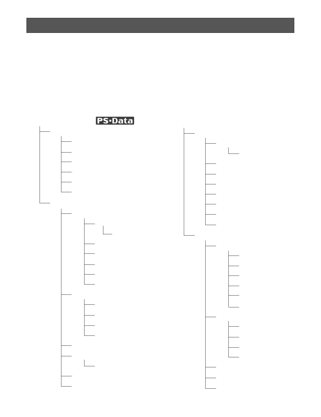
The Setup menu consists of two main menus: one for communication setup for connection to cameras and the system con-
troller WV-CU360, and the other for system setup of the Data Multiplex Unit.
Each of the main menus consists of submenus.
The Setup menu varies between Panasonic Security Data mode and Camera Communication mode. Refer to the description
of communication mode setting with the DIP switches on page 9.
■ Setup Menu
SETUP MENU
COMMUNICATION
UNIT ADDRESS
BAUD RATE
DATA BIT
PARITY CHECK
STOP BIT
WAIT TIME
SYSTEM
ALARM MODE
MONITOR SPOT
MONITOR SPOT
ALARM DISPLAY
SITE ALARM
TERM. ALARM
ALARM OUTPUT
ALARM DATA
COMP/VD2/DATA
CAMERA IN
COMP
VD2
DATA
VS/VD INPUT
CAMERA CONFIG
CAMERA CONFIG
DAISY MODE
TERMINAL
● Panasonic Security Data mode
(see page 12 - 15)
COMMUNICATION
CAM ADDRESS
CAM ADDRESS
BAUD RATE
DATA BIT
PARITY CHECK
STOP BIT
WAIT TIME
DELAY TIME
XON/XOFF
SYSTEM
ALARM MODE
MONITOR SPOT
ALARM DISPLAY
SITE ALARM
TERM. ALARM
ALARM OUTPUT
ALARM DATA
COMP/VD2/DATA
CAMERA IN
COMP
VD2
DATA
VS/VD INPUT
DAISY MODE
TERMINAL
● Camera Communication mode
(see page 16 - 19)
12
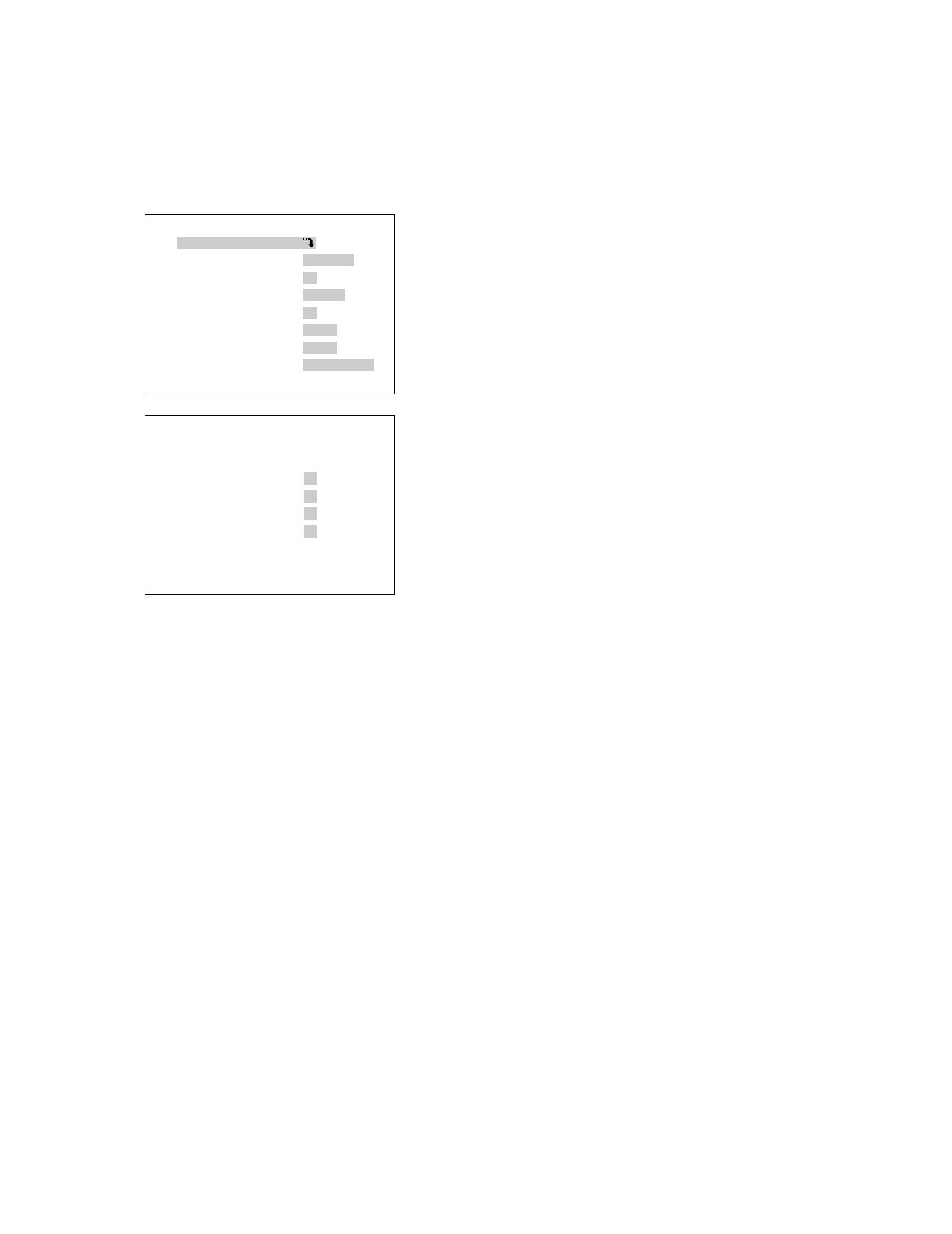
WJ-MP204 SETUP MENU X.XX
COMMUNICATION
SYSTEM
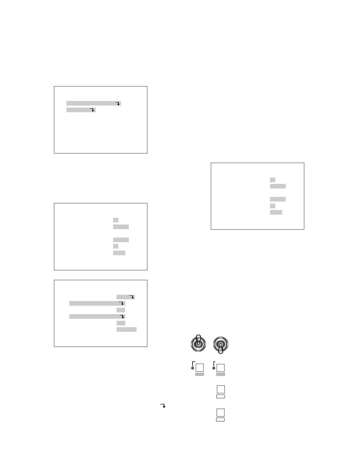
■ Displaying the Setup Menu for
Panasonic Security Data Mode
1. Check that the cameras and peripherals are connected
correctly and securely.
2. Switch all the system components on.
3. Press the SETUP/ESC button for 2 seconds or more.
The Setup menu appears on the monitor.
4. Move the cursor up or down pressing button 1 (C) or
button 2 (D).
5. Press the SUSPEND/SET button. The COMMUNICA-
TION menu or the SYSTEM menu appears on the moni-
tor as shown below.
• The following buttons are used with the Setup menu.
1 (C): To move the cursor down
2 (D): To move the cursor up
3 (–): To select a mode or parameter
4 (+): To select a mode or parameter
SUSPEND/SET: To enter the selections and display
the submenu for the item indicated by the mark
SETUP/ESC: To return to the previous menu
COMMUNICATION
UNIT ADDRESS 1
BAUD RATE 9600
DATA BIT 8
PARITY CHECK NONE
STOP BIT 1
WAIT TIME OFF
SYSTEM
ALARM MODE ON
COMP/VD2/DATA
VS/VD INPUT VD
CAMERA CONFIG
DAISY MODE ON
TERMINAL ALARM
Note:
• To not display the Setup menu for CAMERA OUT pic-
tures, shift the internal switch.(See page 25.)
• To finalize the settings, press the SETUP/ESC button
for 2 seconds or more while the Setup menu is dis-
played.
• To use the System Controller WV-CU360 for operation,
refer to its Operating Instructions.
■ Communication Setup of
Panasonic Security Data Mode
1. Display the Setup menu.
2. Move the cursor to COMMUNICATION by pressing
button 1 (C) or button 2 (D).
Then press the SUSPEND/SET button.
• In case of Panasonic Security Data mode, the COM-
MUNICATION menu appears as shown below.
3. Move the cursor to the desired item by pressing button
1 (C) or button 2 (D), then select the desired mode by
pressing button 3 (–) or button 4 (+).
4. Press the SUSPEND/SET button.
5. After taking the above steps, press the SETUP/ESC
button for 2 seconds or more.
Note: All the settings must be compatible with the
peripherals connected.
• The following buttons are used with the Setup menu for
the WV-CU360. (For Panasonic Security Data mode
only)
COMMUNICATION
UNIT ADDRESS 1
BAUD RATE 9600
DATA BIT 8
PARITY CHECK NONE
STOP BIT 1
WAIT TIME OFF
: To move the cursor up and down
: To select a mode or parameter
: To enter the selections and display
the submenu
: To return to the previous menu
DOWN
LR
UP
LR
STILL
-
EL-ZOOM
+
MON
CAM
ESC
SET
13
COMMUNICATION
UNIT ADDRESS 1
BAUD RATE 9600
DATA BIT 8
PARITY CHECK NONE
STOP BIT 1
WAIT TIME OFF
(6) Wait Time Setting
1. Display the COMMUNICATION menu.
2. Move the cursor to WAIT TIME by pressing button 1
(C) or button 2 (D), then select the desired wait time
(OFF, 100, 200, 400, or 1000 ms) by pressing button 3
(–) or button 4 (+).
The initial factory setting is OFF (No retry).
(1) Unit Address Setting
1. Display the COMMUNICATION menu.
2. Move the cursor to UNIT ADDRESS by pressing button
1 (C) or button 2 (D), then select the desired unit
address in the range of 1 to 99 by pressing button 3 (–)
or button 4 (+).
Notes:
• Check before the above setting that the UNIT
switch is at 0. For address setting, see page 10.
• Before switching the Data Multiplex Unit back on,
remember that address setting with the UNIT
switch has priority to the above setting.
(2) Baud Rate Setting
1. Display the COMMUNICATION menu.
2. Move the cursor to BAUD RATE by pressing button 1
(C) or button 2 (D), then select the desired baud rate
(19200, 9600, 4800, or 2400 bps) by pressing button 3
(–) or button 4 (+).
The initial factory setting is 9600bps.
(3) Data Bit Setting
Setting is fixed for 8 bit.
(4) Parity Check Setting
1. Display the COMMUNICATION menu.
2. Move the cursor to PARITY CHECK by pressing button
1 (C) or button 2 (D), then select the desired type of
parity check (NONE, EVEN or ODD) by pressing button
3 (–) or button 4 (+).
The initial factory setting is NONE.
(5) Stop Bit Setting
1. Display the COMMUNICATION menu.
2. Move the cursor to STOP BIT by pressing button 1 (C)
or button 2 (D), then select the desired number of stop
bits, 1 or 2 by pressing button 3 (–) or button 4 (+).
The initial factory setting is 1 bit.
■ System Setup for Panasonic
Security Data Mode
1. Display the Setup menu.
2. Move the cursor to SYSTEM by pressing button 1 (C)
or button 2 (D), then press the SUSPEND/SET button.
• In case of Panasonic Security Data mode, the SYS-
TEM menu appears as shown below.
SYSTEM
ALARM MODE ON
COMP/VD2/DATA
VS/VD INPUT VD
CAMERA CONFIG
DAISY MODE ON
TERMINAL ALARM
3. Move the cursor to the desired item by pressing button
1 (C) or button 2 (D), then then select the desired
mode by pressing button 3 (–) or button 4 (+).
4. Press the SUSPEND/SET button.
5. After taking the above steps, press the SETUP/ESC
button for 2 seconds or more.
Note: All the settings must be compatible with the
peripherals connected.
14
OFF by pressing button 3 (–) or button 4 (+).
The initial factory setting is ON.
• Terminal Alarm Setting
1. Display the SYSTEM menu.
2. Move the cursor to TERM. ALARM by pressing button 1
(C) or button 2 (D), then select TERM. ALARM ON or
OFF by pressing button 3 (–) or button 4 (+).
The initial factory setting is ON.
• Alarm Output Data (Alarm Output Duration from
Alarm Connector)
1. Display the SYSTEM menu.
2. Move the cursor to ALARM OUTPUT by pressing but-
ton 1 (C) or button 2 (D), then select the desired alarm
output duration, 1S - 30S, 40S, 50S, 1MIN, 2MIN, 3MIN,
4MIN, 5MIN, EXT or OFF, by pressing button 3 (–) or
button 4 (+).
The initial factory setting is 10S. Enable to set by 1 sec-
ond (1S - 30S).
EXT: The alarm signal continues to be output from
ALARM/REMOTE connector till the alarm is reset.
The alarm is not automatically reset.
1S-5MIN: The alarm signal is supplied from ALARM/
REMOTE connector only for the set time. The
alarm is automatically reset after the set time.
(The ALARM indicator changes from blink to
steady light.)
OFF: The alarm signal is not supplied from ALARM/
REMOTE connector. The alarm is not automati-
cally reset.
• Alarm Data
This is to set whether or not the alarm data received
from a camera is to be transmitted to the WV-CU360.
OFF: Select this parameter if the system controller is
not connected to the system, or if operation is
to be controlled via an AV Codec.
0S: Each time an alarm is detected, it is notified to
the system controller.
1S: When an alarm is detected, it is notified to the
system controller. (Alarm data on each channel
where an alarm is detected is stored for 1 sec-
ond, and the stored alarm data is sent to the
system controller.)
5S: When an alarm is detected, it is notified to the
system controller. (Alarm data on each channel
where an alarm is detected is stored for 5 sec-
onds, and the stored alarm data is sent to the
system controller.)
Note: To set 0S, 1S or 5S, the system controller set as
controller No. 1 must be connected to the system.
1. Display the SYSTEM menu.
2. Move the cursor to ALARM DATA by pressing button 1
(C) or button 2 (D), then select the desired alarm data
duration, OFF, 0S, 1S, or 5S, by pressing button 3 (–)
or button 4 (+).
The initial factory setting is 1S.
1. Display the SYSTEM menu.
2. Move the cursor to ALARM MODE by pressing button 1
(C) or button 2 (D), press the SUSPEND/SET button,
then select MONITOR SPOT ON or OFF by pressing
button 3 (–) or button 4 (+).
The initial factory setting is ON.
ON: The screen of the corresponding channel appears
when the alarm is activated. If MONITOR SPOT ON
with the mark is selected, the screen appears
as shown below.
MONITOR SPOT
ALARM CAM NO. PRE
1 1CH -
2 2CH -
3 3CH -
4 4CH -
Enter each camera number and a preset position for
each alarm number. If the Data Multiplex Unit is con-
nected to a combination camera, enter a preset posi-
tion for the PRE parameter.
OFF: The screen continues to display the pictures in
the mode selected previously when the alarm is
activated.
For further information on preset positions, refer to the
Operating Instructions for the combination camera.
• Alarm Display Setting
1. Display the SYSTEM menu.
2. Move the cursor to ALARM DISPLAY by pressing button
1 (C) or button 2 (D), then select ALARM DISPLAY ON
or OFF by pressing button 3 (–) or button 4 (+) so that
[ALARM∗∗∗] appears on the screen or not.
The initial factory setting is ON.
Note: The figure shown in the place of [∗∗∗] after the
word ALARM is a channel number.
• Site Alarm Setting
1. Display the SYSTEM menu.
2. Move the cursor to SITE ALARM by pressing button 1
(C) or button 2 (D), then select SITE ALARM ON or
ALARM MODE
MONITOR SPOT ON
ALARM DISPLAY ON
SITE ALARM ON
TERM.ALARM ON
ALARM OUTPUT 10S
ALARM DATA 1S
(1) Alarm Mode Setting
• Monitor Spot Setting

15
(2) Comp/VD2/Data Setting
• Camera Input Setting
1. Display the SYSTEM menu.
2. Move the cursor to CAMERA IN by pressing button 1
(C) or button 2 (D), press the SUSPEND/SET button,
then select the desired channel 1, 2, 3 or 4 for back-
ground picture by pressing button 3 (–) or button 4 (+).
The initial factory setting is 1CH.
• Cable Compensation Setting
1. Display the SYSTEM menu.
2. Move the cursor to COMP by pressing button 1 (C) or
button 2 (D), press the SUSPEND/SET button, then
select the most suitable cable length by pressing but-
ton 3 (–) or button 4 (+).
S: Less than 400 m (1,300 ft)
M: 400 m (1,300 ft) to 700 m (2,300 ft)
L: 700 m (2,300 ft) to 900 m (3,000 ft)
(When using RG-59U, BELDEN 9259 or equivalent
cable)
The initial factory setting is S.
• VD2 Setting
1. Display the SYSTEM menu.
2. Move the cursor to VD2 by pressing button 1 (C) or
button 2 (D), press the SUSPEND/SET button, then
select ON, OFF, or THRU by pressing button 3 (–) or
button 4 (+).
ON: Multiplex sync signals (VD2) are generated by
synchronizing with the signals sent to the VS/VD IN
connector. If there is no input signal, the internally
generated sync signal (VD2) is multiplexed.
OFF: Sync signal (VD2) is not multiplexed.
THRU: The sync signal (VD2) sent to the CAMERA
OUT connector is multiplexed with the video sig-
nals. If there is no input signal, the sync signal
(VD2) is not multiplexed.
The initial factory setting is ON.
• Data Setting
1. Display the SYSTEM menu.
2. Move the cursor to DATA by pressing button 1 (C) or
button 2 (D), press the SUSPEND/SET button, then
select data communication ON or OFF by pressing but-
ton 3 (–) or button 4 (+).
1. Display the SYSTEM menu.
2. Move the cursor to CAMERA CONFIG by pressing but-
ton 1 (C) or button 2 (D), press the SUSPEND/SET
button, then assign unit numbers, 1 to 128 or - (no
camera), by pressing button 3 (–) or button 4 (+).
Camera numbers are automatically assigned accord-
ing to the UNIT switch settings.
(5) Daisy Mode
1. Display the SYSTEM menu.
2. Move the cursor to DAISY MODE by pressing button 1
(C) or button 2 (D), then select control mode ON or
OFF by pressing button 3 (–) or button 4 (+).
The initial factory setting is ON.
(6) Terminal
1. Display the SYSTEM menu.
2. Move the cursor to TERMINAL by pressing button 1
(C) or button 2 (D), then select ALARM or REMOTE by
pressing button 3 (–) or button 4 (+).
The initial factory setting is ALARM.
Note: To switch from ALARM/REMOTE IN to ALARM/
REMOTE OUT, shift the internal connector of the WJ-
MP204 from the ALM IN connector to the ALM OUT
connector (See page 24).
The initial factory setting of ALARM/REMOTE connector
is ALM IN.
COMP/VD2/DATA
CAMERA IN 1CH
COMP S
VD2 ON
DATA ON
CAMERA CONFIG
CAMERA IN CAM NO.
1CH 1CH
2CH 2CH
3CH 3CH
4CH 4CH
The initial factory setting is ON.
(3) VS/VD Input
1. Display the SYSTEM menu.
2. Move the cursor to VS/VD INPUT by pressing button 1
(C) or button 2 (D), then select VS or VD by pressing
button 3 (–) or button 4 (+).
The initial factory setting is VD.
(4) Camera Config

16
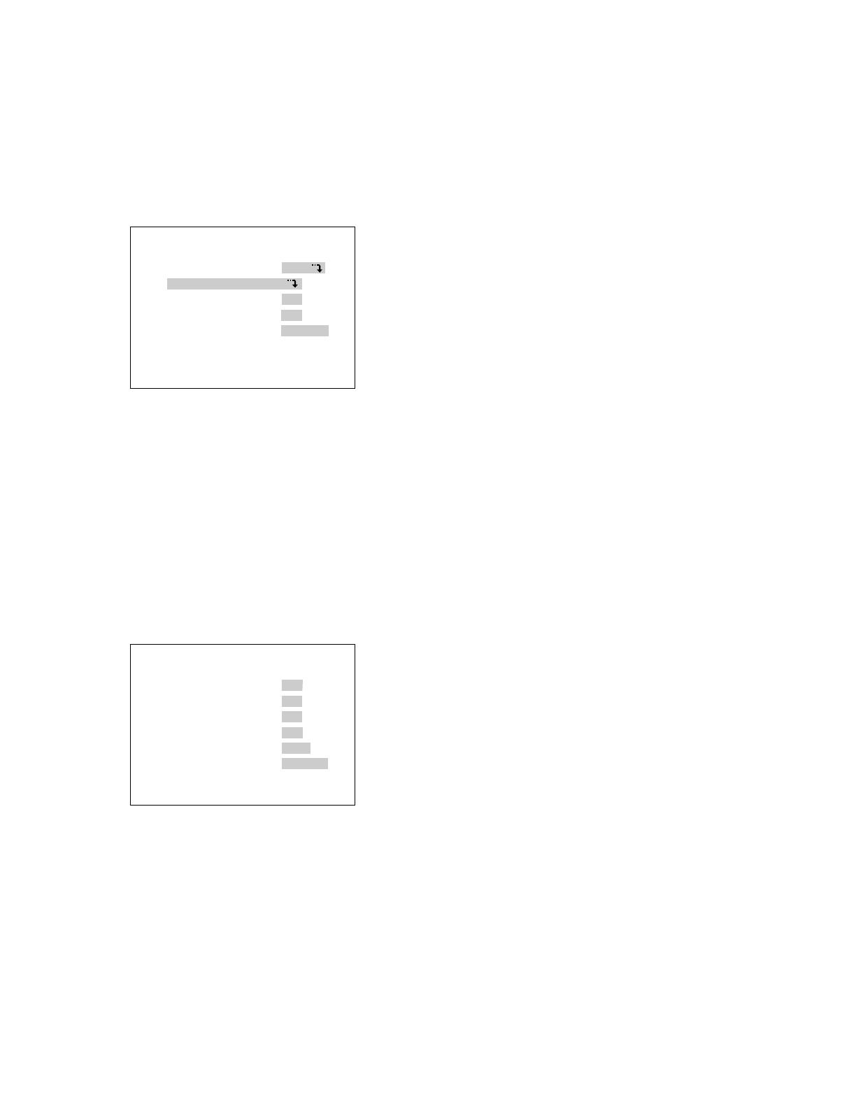
WJ-MP204 SETUP MENU X.XX
COMMUNICATION
SYSTEM
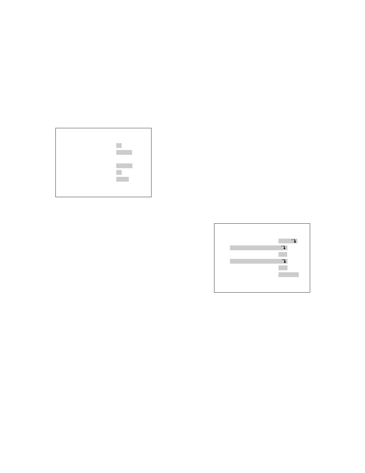
■ Displaying the Setup Menu of
Camera Communication Mode
1. Check that the cameras and peripherals are connected
correctly and securely.
2. Switch all the system components on.
3. Press the SETUP/ESC button for 2 seconds or more.
The Setup menu appears on the monitor.
4. Move the cursor up or down pressing button 1 (C) or
button 2 (D).
5. Press the SUSPEND/SET button. The COMMUNICA-
TION menu or the SYSTEM menu appears on the moni-
tor as shown below.
• The following buttons are used with the Setup menu.
1 (C): To move the cursor down
2 (D): To move the cursor up
3 (–): To select a mode or parameter
4 (+): To select a mode or parameter
SUSPEND/SET: To enter the selections and display
the submenu for the item indicated by the mark
SETUP/ESC: To return to the previous menu.
COMMUNICATION
CAM ADDRESS
BAUD RATE 19200
DATA BIT 8
PARITY CHECK NONE
STOP BIT 1
WAIT TIME OFF
DELAY TIME OFF
XON/XOFF NOT USE
SYSTEM
ALARM MODE ON
COMP/VD2/DATA
VS/VD INPUT VD
DAISY MODE ON
TERMINAL ALARM
Notes:
• To not display the Setup menu for camera output pic-
tures, shift the internal switch. (See page 25.)
• To finalize the settings, press the SETUP/ESC button
for 2 seconds or more while the Setup menu is dis-
played.
• To use the System Controller WV-CU360 for operation,
refer to its Operating Instructions.
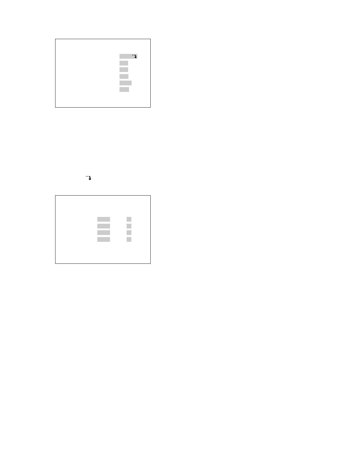
■ Communication Setup for
Camera Communication Mode
1. Display the Setup menu.
2. Move the cursor to COMMUNICATION by pressing
button 1 (C) or button 2 (D). Then press the SUS-
PEND/SET button.
• In case of Camera Communication mode, the
COMMUNICATION menu appears as shown
below.
3. Move the cursor to the desired item by pressing button
1 (C) or button 2 (D), then select the desired mode by
pressing button 3 (–) or button 4 (+).
4. Press the SUSPEND/SET button.
5. After taking the above steps, press the SETUP/ESC
button for 2 seconds or more.
Note: All the settings must be compatible with the
peripherals connected.
COMMUNICATION
CAM ADDRESS
BAUD RATE 19200
DATA BIT 8
PARITY CHECK NONE
STOP BIT 1
WAIT TIME OFF
DELAY TIME OFF
XON/XOFF NOT USE
17
(4) Parity Check Setting
1. Display the COMMUNICATION menu.
2. Move the cursor to PARITY CHECK by pressing button
1 (C) or button 2 (D), then select the desired type of
parity check (NONE, EVEN or ODD) by pressing button
3 (–) or button 4 (+).
The initial factory setting is NONE.
(5) Stop Bit Setting
1. Display the COMMUNICATION menu.
2. Move the cursor to STOP BIT by pressing button 1 (C)
or button 2 (D), then select the desired number of stop
bits, 1 or 2 by pressing button 3 (–) or button 4 (+).
The initial factory setting is 1 bit.
(6) Wait Time Setting
1. Display the COMMUNICATION menu.
2. Move the cursor to WAIT TIME by pressing button 1
(C) or button 2 (D), then select the desired wait time
(OFF, 100, 200, 400, or 1000 ms) by pressing button 3
(–) or button 4 (+).
The initial factory setting is OFF (No retry).
(7) Delay Time Setting
1. Display the COMMUNICATION menu.
2. Move the cursor to DELAY TIME by pressing button 1
(C) or button 2 (D), then select the desired delay time
(OFF, 10, 20, 40, or 100 ms) by pressing button 3 (–) or
button 4 (+).
The initial factory setting is OFF.
(8) XON/XOFF Setting
1. Display the COMMUNICATION menu.
2. Move the cursor to XON/XOFF by pressing button 1
(C) or button 2 (D), then select the desired mode,
NOT USE or USE, by pressing button 3 (–) or button 4
(+).
The initial factory setting is NOT USE.
(1) Camera Addresses Setting
1. Display the COMMUNICATION menu.
2. Move the cursor to CAM ADDRESS by pressing button
1 (C) or button 2 (D), press the SUSPEND/SET button,
and then select the desired camera addresses in the
range of 1 to 99 or No Camera by pressing button 3 (–)
or button 4 (+).
Note:
• Check before the above setting that the UNIT
switch is at 0. For address setting, see page 10.
• Before switching the Data Multiplex Unit back on,
remember that address setting with the UNIT switch
has priority to the above setting.
(2) Baud Rate Setting
1. Display the COMMUNICATION menu.
2. Move the cursor to BAUD RATE by pressing button 1
(C) or button 2 (D), then select the desired baud rate
(19200, 9600, 4800, or 2400 bps) by pressing button 3
(–) or button 4 (+).
The initial factory setting is 19200bps.
(3) Data Bit Setting
1. Display the COMMUNICATION menu.
2. Move the cursor to DATA BIT by pressing button 1 (C)
or button 2 (D), then select the desired number of data
bits, 7 or 8, by pressing button 3 (–) or button 4 (+).
The initial factory setting is 8 bit.
CAM ADDRESS
CAMERA IN ADDRESS
1CH 1
2CH 2
3CH 3
4CH 4
COMMUNICATION
CAM ADDRESS
BAUD RATE 19200
DATA BIT 8
PARITY CHECK NONE
STOP BIT 1
WAIT TIME OFF
DELAY TIME OFF
XON/XOFF NOT USE
18
■ System Setup for Camera
Communication Mode
1. Display the Setup menu.
2. Move the cursor to SYSTEM by pressing button 1 (C)
or button 2 (D), then press the SUSPEND/SET button.
• In case of Camera Communication mode, the SYS-
TEM menu appears as shown below.
SYSTEM
ALARM MODE ON
COMP/VD2/DATA
VS/VD INPUT VD
DAISY MODE ON
TERMINAL ALARM
3. Move the cursor to the desired item by pressing button
1 (C) or button 2 (D), and then select the desired
mode by pressing button 3 (–) or button 4 (+).
4. Press the SUSPEND/SET button.
5. After taking the above steps, press the SETUP/ESC
button for 2 seconds or more.
Note: All the settings must be compatible with the
peripherals connected.
(1) Alarm Mode Setting
• Monitor Spot Setting
1. Display the SYSTEM menu.
2. Move the cursor to ALARM MODE by pressing button 1
(C) or button 2 (D), press the SUSPEND/SET button,
then select MONITOR SPOT ON or OFF by pressing
button 3 (–) or button 4 (+).
The initial factory setting is ON.
ON: The screen of the corresponding channel appears
on the spot output screen when the alarm is activat-
ed.
OFF: The screen continues to display the pictures in
the mode selected previously when the alarm is
activated.
• Alarm Display Setting
1. Display the SYSTEM menu.
2. Move the cursor to ALARM DISPLAY by pressing button
1 (C) or button 2 (D), then select ALARM DISPLAY ON
or OFF by pressing button 3 (–) or button 4 (+) so that
[ALARM∗∗∗] appears on the screen or not.
The initial factory setting is ON.
Note: The figure shown in the place of [∗∗∗] after the
word ALARM is a channel number.
• Site Alarm Setting
1. Display the SYSTEM menu.
2. Move the cursor to SITE ALARM by pressing button 1
(C) or button 2 (D), then select SITE ALARM ON or
OFF by pressing button 3 (–) or button 4 (+).
The initial factory setting is ON.
• Terminal Alarm Setting
1. Display the SYSTEM menu.
2. Move the cursor to TERM. ALARM by pressing button 1
(C) or button 2 (D), then select TERM. ALARM ON or
OFF by pressing button 3 (–) or button 4 (+).
The initial factory setting is ON.
• Alarm Output Data (Alarm Output Duration from
Alarm Connector)
1. Display the SYSTEM menu.
2. Move the cursor to ALARM OUTPUT by pressing button
1 (C) or button 2 (D), then select the desired alarm
output duration, 1S - 30S, 40S, 50S, 1MIN, 2MIN, 3MIN,
4MIN, 5MIN, EXT or OFF, by pressing button 3 (–) or
button 4 (+).
The initial factory setting is 10S. Enable to set by 1 sec-
ond (1S - 30S).
EXT: The alarm signal continues to be output from
ALARM/REMOTE connector till the alarm is
reset. The alarm is not automatically reset.
1S-5MIN: The alarm signal is supplied from ALARM/
REMOTE connector only for the set time. The
alarm is automatically reset after the set time.
(The ALARM indicator changes from blink to
steady light.)
OFF: The alarm signal is not supplied from ALARM/
REMOTE connector. The alarm is not auto-
matically reset.
ALARM MODE
MONITOR SPOT ON
ALARM DISPLAY ON
SITE ALARM ON
TERM.ALARM ON
ALARM OUTPUT 10S
ALARM DATA AUTO2

19
ON: Multiplex sync signals (VD2) are generated by syn-
chronizing with the signals sent to the VS/VD IN
connector. If there is no input signal, the internally
generated sync signal (VD2) is multiplexed.
OFF: Sync signal (VD2) is not multiplexed.
THRU: The sync signal (VD2) sent to the CAMERA OUT
connector is multiplexed with the video signals. If
there is no input signal, the sync signal (VD2) is not
multiplexed.
The initial factory setting is ON.
• Data Setting
1. Display the SYSTEM menu.
2. Move the cursor to DATA by pressing button 1 (C) or
button 2 (D), press the SUSPEND/SET button, then
select data communication ON or OFF by pressing but-
ton 3 (–) or button 4 (+).
The initial factory setting is ON.
(3) VS/VD Input
1. Display the SYSTEM menu.
2. Move the cursor to VS/VD INPUT by pressing button 1
(C) or button 2 (D), then select VS or VD by pressing
button 3 (–) or button 4 (+).
The initial factory setting is VD.
(4) Daisy Mode
1. Display the SYSTEM menu.
2. Move the cursor to DAISY MODE by pressing button 1
(C) or button 2 (D), then select control mode ON or
OFF by pressing button 3 (–) or button 4 (+).
The initial factory setting is ON.
(5) Terminal
1. Display the SYSTEM menu.
2. Move the cursor to TERMINAL by pressing button 1 (C)
or button 2 (D), then select ALARM or REMOTE by
pressing button 3 (–) or button 4 (+).
The initial factory setting is ALARM.
Note: To switch from ALARM/REMOTE IN to ALARM/
REMOTE OUT, shift the internal connector of the WJ-
MP204 from the ALM IN connector to the ALM OUT
connector (See page 24).
The initial factory setting of ALARM/REMOTE connector
is ALM IN.
• Camera Input Setting
1. Display the SYSTEM menu.
2. Move the cursor to CAMERA IN by pressing button 1
(C) or button 2 (D), press the SUSPEND/SET button,
then select the desired channel 1, 2, 3 or 4 for back-
ground picture by pressing button 3 (–) or button 4 (+).
The initial factory setting is 1CH.
• Cable Compensation Setting
1. Display the SYSTEM menu.
2. Move the cursor to COMP by pressing button 1 (C) or
button 2 (D), press the SUSPEND/SET button, then
select the most suitable cable length by pressing but-
ton 3 (–) or button 4 (+).
S: Less than 400 m (1,300 ft)
M: 400 m (1,300 ft) to 700 m (2,300 ft)
L: 700 m (2,300 ft) to 900 m (3,000ft)
(When using RG-59U, BELDEN 9259 or equivalent
cable)
The initial factory setting is S.
• VD2 Setting
1. Display the SYSTEM menu.
2. Move the cursor to VD2 by pressing button 1 (C) or
button 2 (D), press the SUSPEND/SET button, then
select ON, OFF, or THROUGH by pressing button 3 (–)
or button 4 (+).
COMP/VD2/DATA
CAMERA IN 1CH
COMP S
VD2 ON
DATA ON
• Alarm Data
This is to set whether or not the alarm data received
from a camera is to be transmitted to the WV-CU360.
POLLING: Disables to transmit to the system controller
even if an alarm is activated.
AUTO1: Enables to transmit to the system controller
when an alarm is activated.
AUTO2: Enables to transmit to the system controller
when an alarm is activated. Ignores an alarm for 5
seconds after it has transmitted. Enable to transmit
an alarm after it has elapsed for 5 seconds.
1. Display the SYSTEM menu.
2. Move the cursor to ALARM DATA by pressing button 1
(C) or button 2 (D), then select the desired alarm data
mode, POLLING, AUTO1, or AUTO2, by pressing but-
ton 3 (–) or button 4 (+).
The initial factory setting is AUTO2.
(2) Comp/VD2/Data Setting
20
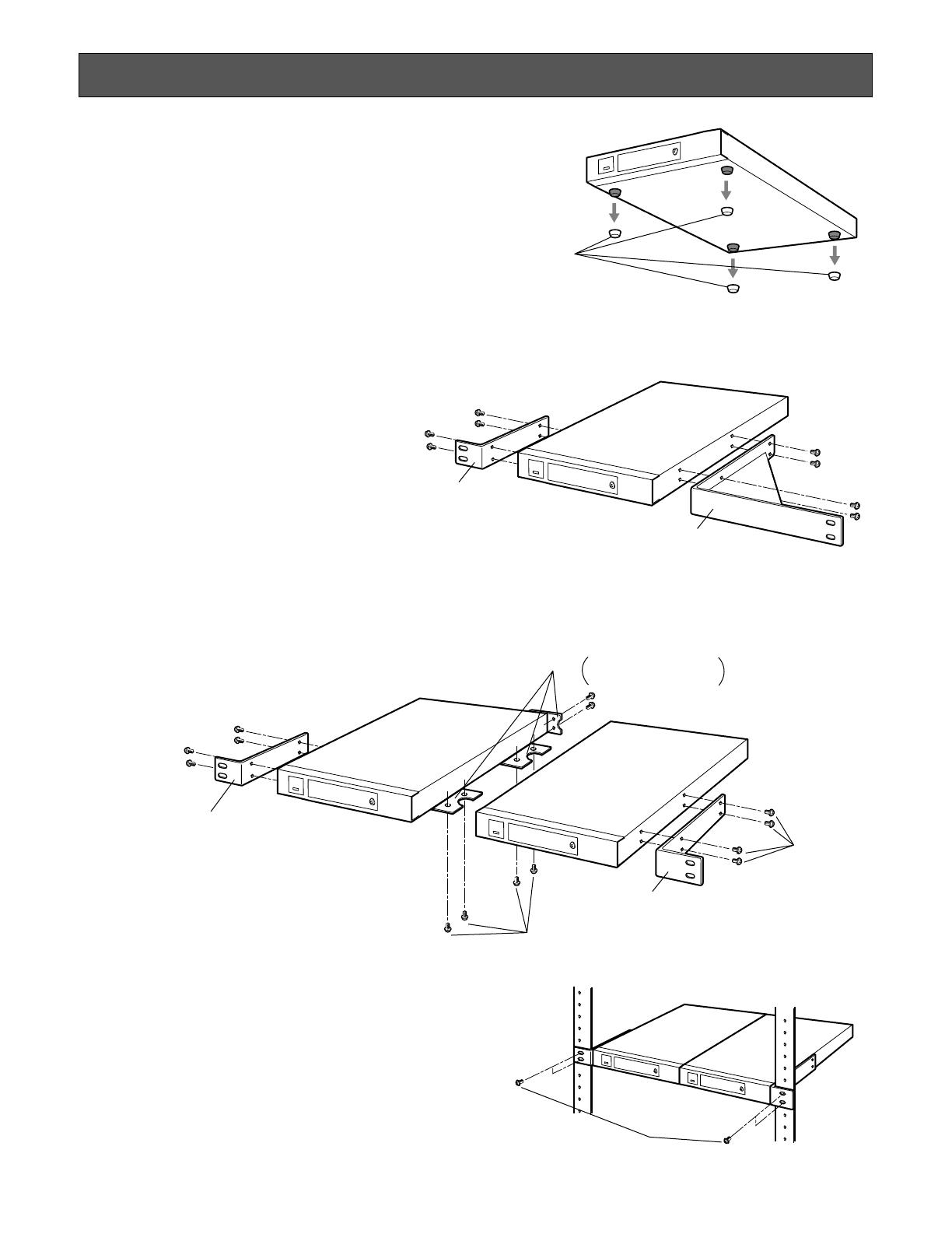
Joint metal
Remove 2 screws from
the rear beforehand.
Rack mounting
bracket (small)
Rack mounting
bracket (small)
Mount screw
Binding head
(M3x8)
Mount screw
Flat head (M3x6)
The installation described below should be made by quali-
fied service personnel or system installers.
■ Mounting in the Rack
Remove the four rubber feet by removing the four screws
from the bottom of the WJ-MP204.
● Mounting One WJ-MP204 with the WV-
Q204/1
1. Fix the mounting brackets (large and small) on both
sides of the WJ-MP204 with the eight supplied screws
(M3x8).
● Mounting two WJ-MP204s With the WV-
Q204/2
1. Place the joint metals on the WJ-MP204s as shown
below and fix them with the supplied screws (M3x6).
Note: Remove the two screws from the rear of each
WJ-MP204s and fasten it with the eight supplied
screws (M3x8).
2. Install the WJ-MP204s with the rack
mounting brackets on the rack using
four screws (not supplied).
Cautions:
• Do not block the ventilation opening or slots in the
cover to prevent the appliance from overheating.
Always keep temperature in the rack within +45°C
(113°F).
• Secure the rear of the appliance to the rack by using
additional mounting brackets (procured locally), if the
rack is subject to vibration.
• Do not use tapping screws for installing the WJ-MP204
on the rack with the rack mounting brackets.
INSTALLATION
Rubber feet
Rack mounting
bracket (small)
Rack mounting
bracket (large)
Rack mounting screws
/