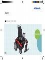
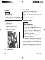
Otto Bock B600 Instructions For Use Manual
- Type
- Instructions For Use Manual

Instructions for Use (User)
B600

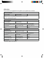
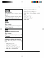
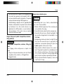
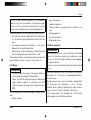
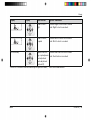
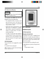
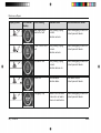
Additional options
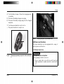
The power wheelchair can be equipped with the following additional options (applicable options are checked):
Electronic drive-away lock*
[ ] Function enabled [ ] Function disabled
If enabled, the function is activated by pressing the mode button on the control panel.
The function is deactivated with the joystick.
Electronic steering lock*
[ ] Function enabled [ ] Function disabled
The electronic steering lock is turned on or off with the following button when the motors are at a standstill:
[ ] Warning flasher [ ] Direction indicator, right [ ] Direction indicator, left
[ ] Horn [ ] Light [ ] Mode
2-way adapter cable*
[ ] Adapter cable included [ ] Adapter cable not included
The included adapter cable allows the following functions to be selected directly through separate buttons:
[ ] Footrest, left [ ] Footrest, right [ ] Seat tilt
[ ] Seat height adjustment [ ] Back angle adjustment [ ] Light
[ ] Direction indicator, right [ ] Direction indicator, left [ ] Horn
[ ] Warning flasher [ ] Other:
*See the section 'Usage' for more information.

Ottobock | 3B600
Foreword 1 6...............................................................
Product Description2 7.............................................
Function 2.1 7..........................................................
Product Overview2.2 7..............................................
Safety3 8.....................................................................
Explanation of Warning Symbols3.1 8.........................
General Safety Instructions3.2 8................................
Reference to additional safety instructions3.3 9............
Name plate and warning labels3.4 10.........................
Name plate3.4.1 10.....................................................
Warning labels3.4.2 11................................................
Delivery4 12................................................................
Scope of supply4.1 12..............................................
Options4.2 12..........................................................
Model B6004.2.1 12....................................................
Storage4.3 12..........................................................
During daily use4.3.1 12..............................................
In case of extended disuse4.3.2 12...............................
Preparation for Use5 13............................................
Safety Instructions5.1 13...........................................
Initial operation5.2 14...............................................
Locking the back angle adjustment in place5.2.1 14........
Adjustments5.3 15....................................................
Prerequisites5.3.1 15..................................................
Adjusting the back angle5.3.2 15..................................
Adjusting the side panels5.3.3 16..................................
Adjusting the footrests5.3.4 17.....................................
Adjusting the belt lengths5.3.5 18.................................
Adjusting the control panel5.3.6 18...............................
Adjusting the telescoping front frame5.3.7 19.................
Changing control unit parameters5.3.8 19......................
Usage6 20...................................................................
Side panels6.1 20....................................................
Footrests6.2 21........................................................
Getting in / transfer6.3 21..........................................
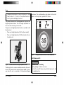
Control unit6.4 23....................................................
Control Panel6.4.1 23..................................................
Buttons and display functions6.4.2 24...........................
Driving Functions6.5 27............................................
Safety Instructions6.5.1 27...........................................
Driving notes6.5.2 30..................................................
Switching on and off6.5.3 31........................................
Selecting the speed levels6.5.4 31................................
Driving6.5.5 32...........................................................
Range6.5.6 33............................................................
Table of contents
Table of contents

Drive-away lock6.5.7 33...............................................
Steering lock6.5.8 35..................................................
Adjusting the driving characteristics6.5.9 35...................
Enabling/disabling the brakes6.6 36...........................
Batteries/charging process6.7 38...............................
Safety Instructions6.7.1 38...........................................
General6.7.2 38..........................................................
Battery charging information6.7.3 38.............................
Battery charger6.7.4 39...............................................
Charging the battery6.7.5 40........................................
Power seat functions6.8 41........................................
Safety Instructions6.8.1 41...........................................
Power seat height adjustment6.8.2 43...........................
Power seat tilt6.8.3 44.................................................
Power back angle adjustment6.8.4 45...........................
Power footrests6.8.5 46...............................................
Controlling power seat functions6.8.6 47.......................
Joystick and display functions6.8.7 48...........................
Manual seat functions6.9 50......................................
Safety Instructions6.9.1 50...........................................
Manual elevating footrests6.9.2 50................................
Additional seat options6.10 50.....................................
Contour seat6.10.1 50...................................................
Recaro® seat6.10.2 51...................................................
Headrest6.10.3 53........................................................
Control unit accessories6.11 54...................................
Separate LCD monitor6.11.1 54.....................................
Attendant control6.11.2 60.............................................
Push-button module6.11.3 62.........................................
Special controls6.11.4 64..............................................
Adapter cable for Piko button6.11.5 65............................
External odometer6.11.6 65............................................
Additional options6.12 65............................................
Control panel holder6.12.1 65........................................
Lights6.12.2 66............................................................
Belts / belt systems6.12.3 67..........................................
Suspension (steering casters/drive wheels)6.12.4 69........
Locking the steering casters6.12.5 70.............................
Rear bumper6.12.6 70...................................................
Overview of additional options6.12.7 71..........................
Disassembly/transport6.13 71.....................................
Safety Instructions6.13.1 71...........................................
Reducing the transportation size6.13.2 72.......................
Reducing the transportation size – Recaro®
seat
6.13.3
73...............................................................
Preparing for transport6.13.4 73.....................................
Use in a wheelchair accessible vehicle6.14 74...............
Safety Instructions6.14.1 74...........................................
Permitted use6.14.2 74..................................................
Restrictions for Use6.14.3 75.........................................
Necessary accessories6.14.4 75....................................
4 | Ottobock B600
Table of contents

Use6.14.5 75................................................................
Care6.15 75..............................................................
Safety Instructions6.15.1 75...........................................
Cleaning6.15.2 76........................................................
Disinfection6.15.3 76....................................................
Maintenance/Repair7 76..........................................
Safety Instructions7.1 76...........................................
Maintenance7.2 77...................................................
Maintenance intervals7.2.1 78......................................
Repair7.3 80............................................................
Replacing a defective fuse7.3.1 80................................
Replacing a defective bulb7.3.2 81................................
Replacing the battery7.3.3 82.......................................
Troubleshooting7.4 82..............................................
Types of notifications7.4.1 83.......................................
Wheelchair control unit fault overview7.4.2 84................
Attendant control fault overview7.4.3 87.........................
Disposal8 89...............................................................
Safety Instructions8.1 89...........................................
Disposal Information8.2 89........................................
Legal Information9 89...............................................
Service life9.1 89......................................................
Liability9.2 89..........................................................
CE Conformity9.3 89................................................
Warranty terms9.4 90...............................................
Trademarks9.5 90....................................................
Appendices10 91..........................................................
Technical data10.1 91.................................................
Ottobock | 5B600
Table of contents

1 Foreword
INFORMATION
Date of the last update: 2013-09-10
► Please read this document carefully.
► Follow the safety instructions.
INFORMATION
► These instructions for use (user) can be viewed and
downloaded from the homepage www.ottobock.com. It
is possible to increase the display size of the PDF doc
ument stored there.
► Please note that the instructions for use are revised
regularly. The latest version can be viewed and down
loaded on the respective product page at
www.ottobock.com.
► For further questions about the instructions for use
(user), please contact the qualified personnel who
issued the product to you.
With this wheelchair, you have purchased a high quality
product which can be put to versatile, daily use at home and
outdoors.
Be sure to read these instructions for use before you start
using the wheelchair. In particular, please observe the
information in the chapters "Safety" and "Use".
Please note the following:
• If you have any questions or cannot solve a problem
despite reading these instructions for use, please con
tact the qualified personnel who fitted the product or the
manufacturer's service department (please see inside
back cover or back cover for addresses).
• All users and/or attendants must be instructed by the
qualified personnel in the use of the product with the aid
of these instructions for use. In particular, users and/or
attendants must be informed of the residual risk with the
aid of the safety instructions in these instructions for
use.
• The product has been adapted to the needs of the user.
Further changes may be made only by qualified person
nel. The manufacturer recommends checking the set
tings regularly in order to assure an optimum fit over the
long term. Especially for children and youth, they should
be checked every six months.
• The product may be combined only with the options lis
ted here. The manufacturer assumes no liability for com
binations with third-party medical devices and/or
accessories not included in the modular system.
• Please note also the information in the chapter "Liabil
ity".
6 | Ottobock B600
Foreword

Ottobock | 7B600
• The operational safety of the wheelchair can only be
ensured if it is used properly in accordance with the
information contained in these instructions for use. The
user is ultimately responsible for accident-free opera
tion.
• Your wheelchair model may differ from the models
shown. In particular, not all the options described in
these instructions for use will be installed on your wheel
chair.
• We reserve the right to make technical changes to the
model described in these instructions for use.
2 Product Description
2.1 Function
The wheelchair is designed solely for individual use by per
sons who are unable to walk or who have a walking impedi
ment, and can be operated either by the patient or by anoth
er person.
The wheelchair can be used on solid ground both indoors
and outdoors.
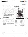
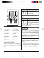
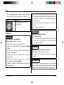
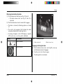
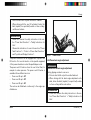
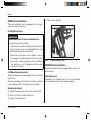
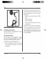
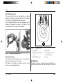
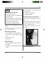
2.2 Product Overview
Fig. 1 Main components
1 Backrest 7 Caster wheel
2 Side panel 8 Anti-tipper
3 Control panel 9 Drive wheel
4 Footrest 10 Bumper
5 Charging receptacle 11 Rear LED lights
6 Motor cover 12 Back angle adjustment
Product Description

8 | Ottobock B600
3 Safety
3.1 Explanation of Warning Symbols
WARNING
Warnings regarding possible risks of severe
accident or injury.
CAUTION
Warnings regarding possible risks of acci
dent or injury.
NOTICE
Warnings regarding possible technical dam
age.
3.2 General Safety Instructions
WARNING
Improper product operation
Falling, tipping over, collision due to user error
► The product may only be used by a qualified user.
► As a user or attendant, you must be trained in the use
of the product by qualified personnel instructed by the
manufacturer.
► Read the entire instructions for use.
► The product may not be used in case of exhaustion or
under the influence of alcohol or medications.
► The product may not be used in road traffic by users
who have any mental limitations which can temporarily
or permanently limit attentiveness and judgement.
► You must observe road traffic regulations when driving
in road traffic.
WARNING
Failure to heed or observe the safety instructions
Risk of pinching, crushing, being pulled in, tipping, falling
► Observe all safety instructions in these instructions for
use and in all other applicable documents.
WARNING
Improper use of the product
Risk of pinching, crushing, being pulled in, tipping, falling
► Only use this product for its original intended purpose.
► Only one person may be transported with the product
at any one time.
CAUTION
Seat cushion or backrest cover may ignite
User may sustain burns
► The seat cushion and backrest cover are not highly
flammable, but there is a possibility they may catch fire.
Therefore utmost caution is required near open flame.
► Keep away from any sources of fire, especially burning
cigarettes.
Safety

Ottobock | 9B600
CAUTION
Extreme temperatures
Risk of hypothermia or burns on components, failure of
components
► Do not expose the product to any extreme temperat
ures (e.g. direct sunlight, sauna, extreme cold).
NOTICE
Overloading
Damage to the product
► Do not exceed the maximum load capacity (see the
section "Technical Data").
NOTICE
Use under incorrect environmental conditions
Damage to the product
► Only use the product within a temperature range of -25
°C to +50 °C.
3.3 Reference to additional safety instructions
Observe additional safety instructions in the following
chapters:
• Chapter "Preparation for Use"
• Chapter "Usage" > "Driving Functions"
• Chapter "Usage" > "Batteries/Charging Process"
• Chapter "Usage" > "Power Seat Functions"
• Chapter "Usage" > "Manual Seat Functions"
• Chapter "Usage" > "Disassembly/Transport"
• Chapter "Usage" > "Use in a Wheelchair Accessible
Vehicle"
• Chapter "Usage" > "Care"
• Chapter "Maintenance/Repair"
• Chapter "Disposal"
Safety

3.4 Name plate and warning labels
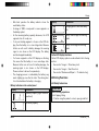
3.4.1 Name plate
Label Meaning
A Type designation
B Read the instructions for use before using the product. Observe
safety information in the instructions for use.
C Symbol for separate collection of electrical and electronic devices.
Components of the power wheelchair and batteries may not be dis
posed of in household waste.
D European article number (EAN)
E Product reference number
F Serial number (including year of manufacture)
G Maximum load capacity (see section 'Technical data')
H Maximum climbing ability (see section 'Technical data')
I Maximum speed (see section 'Technical data')
J Allowable axle load, front
K Allowable axle load, rear
L Maximum gross weight
M Manufacturer information/address
The nameplate is located on the side of the
frame below the seat.
N CE marking – product safety in accordance with EU directives
10 | Ottobock B600
Safety

Ottobock | 11B600
3.4.2 Warning labels
Label Meaning
A Electric driving mode: lock motor brake
B Manual driving mode: unlock motor brake
Risk of pinching. Do not reach into the danger area.
Safety

4 Delivery
4.1 Scope of supply
The power wheelchair is normally shipped fully assembled
and fitted to the personal requirements of the respective
user.
The scope of delivery includes:
• Fitted power wheelchair with main components
• Installed options
• Battery charger
• Instructions for Use (user)
4.2 Options
The standard model can be fitted to the user's personal
requirements through a large range of options.
A full list of the available modules and accessories is shown
on the order form and in the accessories catalogue.
To use options: see Page20 et. seq.
4.2.1 Model B600
The B600 power wheelchair with telescoping frame can be
equipped with up to four of the following power seat
options:
• Power seat height adjustment
• Power seat tilt available in three different versions (up to
20°, up to 30° and up to 45°)
• Power back angle adjustment up to 30°
• Electrically adjustable footrests with three program
mable versions (control of only left, only right or both
sides)
The wheelchair is controlled by an enAble50 control unit. An
optional LCD monitor is available for the control unit. It
enables special controls to be connected, among other
things.
For additional information on enabling/user specific adjust
ment of certain enAble50 control unit functions: see inside
front cover.
4.3 Storage
4.3.1 During daily use
The power wheelchair should always be protected against
external influences.
The control unit must be turned off.
4.3.2 In case of extended disuse
NOTICE
Deep discharge due to standby current
Risk of battery damage
► Remove the fuse if the wheelchair is not used for more
than 3 days.
INFORMATION
To remove the fuse, see section "Repair" > "Replacing a
defective fuse".
12 | Ottobock B600
Delivery

Ottobock | 13B600
Please observe the following if the power wheelchair is not
used for more than 3days:
Storage conditions
• Maintain an ambient temperature between -40°C and
+65°C and a relative humidity between 45% and 85%.
• Store the power wheelchair in a dry, enclosed room with
sufficient air circulation and protection from external
influences.
• Protect the wheels against ground frost, e.g., by reliev
ing them completely through assembly blocks or
wooden boards.
• Fill the wheels with slight overpressure and rotate them
at regular weekly intervals to prevent flat tyres from
extended standing.
Note regarding the tyres
• If the power wheelchair is not moved for several days,
permanent colour changes may occur where the wheel
chair comes into contact with the surface it is standing
on. Therefore a suitable underlay should be used if the
product is parked for extended periods of time.
• Tyres contain chemical substances that can react with
other chemical substances (such as cleaning agents,
acids, etc.).
• Black tyres contain soot particles. They may leave black
marks where they come into contact with the ground.
Therefore the manufacturer recommends grey tyres if
the wheelchair is primarily used indoors.
• Avoid unnecessary parking outdoors. Direct exposure to
sunlight/UV radiation causes the tyres to age more
quickly. As a result, the tread surface hardens and
corner pieces break out of the tread.
• The tyres must be changed when the tread is less than 1
mm to ensure safe driving behaviour.
• The tyres should be replaced every 2 years regardless
of wear and tear.
5 Preparation for Use
5.1 Safety Instructions
WARNING
Improper modification of the settings
Risk of tipping, falling, improper user posture
► Do not modify the settings established by the qualified
personnel.
► In case of problems with the settings (control panel
problems etc.), please contact the qualified personnel
who fitted your product.
WARNING
Improper handling of packaging materials
Risk of suffocation
► Keep packaging materials away from children.
Preparation for Use

14 | Ottobock B600
CAUTION
Uncontrolled movement of components when making
adjustments
Risk of crushing, pinching, blows to limbs
► Ensure that body parts, such as hands or head, are
never in the danger zone.
► Perform the work with the aid of a helper for support.
CAUTION
Unsecured screw connections
Risk of pinching, crushing, tipping over, falling of user
► After all adjusting/readjusting work, retighten the
mounting screws/nuts firmly. Observe any torque set
tings which may be specified.
► Any time you loosen a screw connection with thread
lock, replace it with a new screw connection or secure
the old screw connection with medium strength thread
locker (e.g. Loctite 241
®
).
5.2 Initial operation
The specialist dealer ships the power wheelchair fully
assembled and ready to use.
The following additional tasks may be required:
• Adjusting settings: see Page15 et. seq.
• Installing the side panels: see Page20
• Installing the footrests: see Page21
• Charging the battery: see Page38 et. seq.
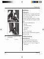
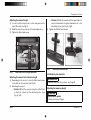
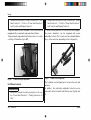
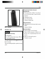
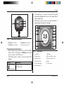
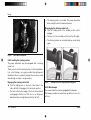
5.2.1 Locking the back angle adjustment in place
If the power wheelchair is equipped with mechanical/power
back angle adjustment, proceed as follows if necessary:
1) Fold the backrest up.
2) Place the cross bolt on the end of the gas compression
spring or actuator into the bracket (see Fig.2, item 1).
3) Push the lever down until the lock engages (see Fig.2,
item 2).
4) Check the bolt and lock to ensure that they are securely
engaged.
Preparation for Use

Ottobock | 15B600
Fig. 2 Place the cross bolt into the bracket (top); locked
cross bolt (bottom)
1 Cross bolt 2 Lock with lever
5.3 Adjustments
5.3.1 Prerequisites
Fine fitting/adjusting work should always be performed with
the user. The user should sit upright in the power wheel
chair while adjustments are made.
Seat height, seat width and seat angle are set according to
the customer order and may only be changed by a specialist
dealer.
The following can be adjusted by the user:
• Back angle
• Armrest height and position
• Lower leg length
• Strap lengths
• Position of the control panel
All parts of the product should be cleaned thoroughly before
adjustments are made.
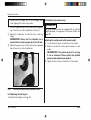
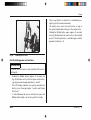
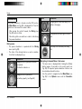
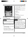
5.3.2 Adjusting the back angle
Standard/contour seat
1) Pull on the strap until the locking bolts are free.
2) Change the backrest angle to the desired position.
3) Release the strap. The locking bolts engage at the
desired position.
Preparation for Use

16 | Ottobock B600
Fig. 3 Adjusting the back angle
1 Release/locking strap 2 Locking bolts
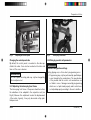
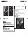
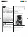
Recaro® seat
WARNING
Incorrect Recaro® Seat settings
Risk of falling, tipping
► Note that the maximum backrest angle is 30° while
standing and 20° while driving.
INFORMATION
For further Recaro® seat settings: see the chapter
"Recaro® seat".
► Turn the knob on the left or right side of the backrest
until the backrest is in the desired position (see Fig.4,
item 2).
Fig. 4 Adjusting the Recaro® seat angle
1 Release handle
2 Back angle adjustment knob
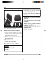
5.3.3 Adjusting the side panels
INFORMATION
To remove and install the side panels: see Page20.
Preparation for Use

Ottobock | 17B600
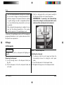
Adjusting the armrest height
1) Loosen the Allen head screw on the side panel with a
size 3 Allen key (see Fig.5).
2) Slide the armrests up or down to the desired position.
3) Tighten the Allen head screw.
Fig. 5 Allen head screw for height adjustment
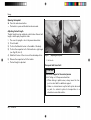
Adjusting the armrest to the forearm length
1) Depending on the version, loosen 2 x Allen head screws
on the bottom of the armrest (see Fig.6).
2) Adjusting the armrest:
→ Version 1:Push the armrest along the slotted holes
to the front or back into the desired position ((see
Fig.6), left).
→ Version 2: Slide the armrest with the spare tube for
ward or backwards along the attachment rail to the
desired position ((see Fig.6), right).
3) Tighten the 2 Allen head screws.
Fig. 6 Adjusting the armrest depth
5.3.4 Adjusting the footrests
INFORMATION
To remove and install the footrests: see Page21.
Adjusting the lower leg length
CAUTION
Exposed pinch points
Pinching, crushing of fingers
Preparation for Use

18 | Ottobock B600
► Ensure that your fingers are not in the danger area
when flipping the footrests up or down.
1) Loosen the grub screws or Allen head screws (depend
ing on the version) on the footplate bar (see Fig.7).
2) Adjust the footplate bar to match the user's lower leg
length.
INFORMATION: Ensure that the footplate bar is
inserted into the swivel segment by at least 40mm.
3) Tighten the grub screws or Allen head screws (depend
ing on the version) on the footplate bar.
Fig. 7 Adjusting the lower leg length (standard footrest)
5.3.5 Adjusting the belt lengths
To adjust the belt lengths: see Page67.
5.3.6 Adjusting the control panel
INFORMATION
The power wheelchair may be equipped with an optional
height-adjustable or swing-away control panel holder (see
Page65).
Adjusting the control panel to the forearm length
1) Loosen the 3 set screws on the bottom of the armrest.
2) Slide the rail with the control panel forwards or back
wards.
INFORMATION: If the control panel rail is too long
it can be shortened. Please contact the qualified
personnel who adjusted your product.
3) Tighten the 3 set screws on the bottom of the armrest.
Preparation for Use

Ottobock | 19B600
Fig. 8 Adjusting the control panel
Changing the control panel side
By default, the control panel is mounted on the side spe
cified in the order. It can also be mounted on the other side
later on if the user so desires.
INFORMATION
The control panel mounting side may only be changed by
authorised personnel.
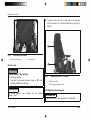
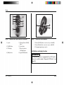
5.3.7 Adjusting the telescoping front frame
The telescoping front frame of the power wheelchair allows
the wheelbase to be adapted to the respective seat (see
Fig.9). Because this adjustment involves the displacement
of the centre of gravity, it may only be carried out by quali
fied personnel.
Fig. 9 Telescoping front frame
5.3.8 Changing control unit parameters
WARNING
Incorrect configuration settings
Falling, tipping over, collision due to programming errors
► Programming may only be performed by qualified per
sonnel trained by the manufacturer. The manufacturer
of the product and the control unit manufacturer are
not liable in case of damage caused by programming
which was not performed properly and/or which was
not adjusted properly according to the user's abilities.
Preparation for Use

20 | Ottobock B600
► Note that modified parameter settings in the configura
tion can lead to changes in driving characteristics. In
particular, changes to the speed, acceleration, braking
or joystick settings can lead to unexpected and there
fore uncontrollable driving characteristics and cause
an accident.
► After configuration/programming is complete, the user
must test the driving characteristics of the product
under the supervision of the qualified personnel.
If necessary, the qualified personnel can fit the already pre
programmed wheelchair control system and accessories to
the specific user requirements.
6 Usage
6.1 Side panels
INFORMATION
For additional information on side panels with lighting: see
Page66.
Removing the side panel
1) Loosen the wing screw on the side panel holder (see
Fig.10).
2) Pull the side panel out from the side panel holder and
set it aside.
3) Only for a side panel with a control panel: carefully let
the side panel with the control panel hang down.
INFORMATION: If necessary, the hook-and-loop
closures for routing the control panel cable can be
undone and the control panel can be removed.
Fig. 10 Side panel wing screw
Installing the side panel
1) If necessary, install the control panel and fasten the
hook-and-loop closures for routing the control panel
cable.
2) Insert the side panel into the side panel holder.
3) Re-tighten the wing screw on the side panel holder.
Usage
Page is loading ...
Page is loading ...
Page is loading ...
Page is loading ...
Page is loading ...
Page is loading ...
Page is loading ...
Page is loading ...
Page is loading ...
Page is loading ...
Page is loading ...
Page is loading ...
Page is loading ...
Page is loading ...
Page is loading ...
Page is loading ...
Page is loading ...
Page is loading ...
Page is loading ...
Page is loading ...
Page is loading ...
Page is loading ...
Page is loading ...
Page is loading ...
Page is loading ...
Page is loading ...
Page is loading ...
Page is loading ...
Page is loading ...
Page is loading ...
Page is loading ...
Page is loading ...
Page is loading ...
Page is loading ...
Page is loading ...
Page is loading ...
Page is loading ...
Page is loading ...
Page is loading ...
Page is loading ...
Page is loading ...
Page is loading ...
Page is loading ...
Page is loading ...
Page is loading ...
Page is loading ...
Page is loading ...
Page is loading ...
Page is loading ...
Page is loading ...
Page is loading ...
Page is loading ...
Page is loading ...
Page is loading ...
Page is loading ...
Page is loading ...
Page is loading ...
Page is loading ...
Page is loading ...
Page is loading ...
Page is loading ...
Page is loading ...
Page is loading ...
Page is loading ...
Page is loading ...
Page is loading ...
Page is loading ...
Page is loading ...
Page is loading ...
Page is loading ...
Page is loading ...
Page is loading ...
Page is loading ...
Page is loading ...
Page is loading ...
Page is loading ...
-
 1
1
-
 2
2
-
 3
3
-
 4
4
-
 5
5
-
 6
6
-
 7
7
-
 8
8
-
 9
9
-
 10
10
-
 11
11
-
 12
12
-
 13
13
-
 14
14
-
 15
15
-
 16
16
-
 17
17
-
 18
18
-
 19
19
-
 20
20
-
 21
21
-
 22
22
-
 23
23
-
 24
24
-
 25
25
-
 26
26
-
 27
27
-
 28
28
-
 29
29
-
 30
30
-
 31
31
-
 32
32
-
 33
33
-
 34
34
-
 35
35
-
 36
36
-
 37
37
-
 38
38
-
 39
39
-
 40
40
-
 41
41
-
 42
42
-
 43
43
-
 44
44
-
 45
45
-
 46
46
-
 47
47
-
 48
48
-
 49
49
-
 50
50
-
 51
51
-
 52
52
-
 53
53
-
 54
54
-
 55
55
-
 56
56
-
 57
57
-
 58
58
-
 59
59
-
 60
60
-
 61
61
-
 62
62
-
 63
63
-
 64
64
-
 65
65
-
 66
66
-
 67
67
-
 68
68
-
 69
69
-
 70
70
-
 71
71
-
 72
72
-
 73
73
-
 74
74
-
 75
75
-
 76
76
-
 77
77
-
 78
78
-
 79
79
-
 80
80
-
 81
81
-
 82
82
-
 83
83
-
 84
84
-
 85
85
-
 86
86
-
 87
87
-
 88
88
-
 89
89
-
 90
90
-
 91
91
-
 92
92
-
 93
93
-
 94
94
-
 95
95
-
 96
96


Otto Bock B600 Instructions For Use Manual
- Type
- Instructions For Use Manual
Ask a question and I''ll find the answer in the document
Finding information in a document is now easier with AI
Related papers
-
Otto Bock ParaGolfer Service Instructions Manual
-
-
-
Otto Bock B500 advanced User Instructions
-
-
-
-
-
-
Other documents
-
Human Touch HT-5040 User manual
-
 CLATINA Ergonomic High Swivel Executive Chair User manual
-
 CLATINA Ergonomic High Swivel Executive Chair User manual
-
Yuwell D130HL User manual
-
Fly B600 Hard reset manual
-
BakkerElkhuizen BNEFFSL Datasheet
-
Pride i-Go Owner's manual
-
Ottobock Discovery Operating instructions
-
Anthro Elevate II Adjusta User manual
-
 Freerider FR-W04 User Instruction Manual


