Page is loading ...

1
© Copyright 2007, DB Industries, Inc.
WARNING: This product is part of a fall arrest system.
These instructions must be provided to all users
and rescuers (see section 8 Terminology) using this
equipment. The user must read and understand these
instructions before using this equipment. The user
must follow the manufacturer’s instructions for each
component of the system. Manufacturer’s instructions
must be followed for proper use and maintenance of
this equipment.
Alterations or misuse of this equipment,
or failure to follow instructions, may result in serious
injury or death.
IMPORTANT: If you have questions on the use, care,
or suitability of this equipment for your application,
contact DBI‑SALA.
IMPORTANT: Before using this equipment, record the
product identication information from the ID label into
the inspection and maintenance log in section 10.0 of
this manual.
1.0 APPLICATIONS:
1.1 PURPOSE: DBI-SALA’s Parapet Wall Anchor is a portable anchorage connector designed for fall arrest
applications and was developed to be used in locations where a low parapet wall provides an anchor site. Do
not hang, lift or support tools or equipment from this device.
A. FALL ARREST: In this application, the parapet wall anchor is used as part of a complete fall arrest
system. Such systems typically include a full body harness, and must include either a shock absorbing
lanyard or self retracting lifeline. Maximum permissible free fall is 6 feet (1.8 m).
1.2 LIMITATIONS: The following application limitations must be recognized and considered before using this
product:
A. ANCHORAGE: This anchorage connector system is intended to be installed on a parapet wall up to 14
1/2 inches (36.8 cm) thick and the wall must meet the anchorage strength requirements as set forth in
section 2.4.
B. CAPACITY: This anchorage connector system is designed for use by persons with a combined weight
(person, clothing, tools, etc.) of no more than 310 lbs. (141 kg). Only one personal protective system
may be connected to the anchorage connector.
C. FREE FALL: Personal fall arrest systems must be rigged in such a way as to limit the free fall to a
maximum of 6 feet (1.8 m) (Ref. ANSI Z359.1). See associated connecting subsystem manufacturer’s
instructions for further information.
D. FALL CLEARANCE: Make certain that enough clearance exists in all potential fall paths to prevent
striking an object. The amount of clearance needed is dependent upon the type of connecting subsystem
used (ie. shock absorbing lanyard or self retracting lifeline), and the anchorage location. Refer to
manufacturer’s instructions of the connecting subsystem or component for more information on fall
clearance.
USeR INSTRUCTION MANUAL
fOR PARAPeT WALL ANChOR
This manual is intended to meet the Manufacturer’s Instructions as required by ANSI Z359.1, and the Canadian
Standards Association, and should be used as part of an employee training program as required by OSHA.
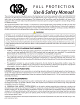
Figure 1 - Steel Plate Anchor
2 x Set
Screws
D-Ring
Instructions for the following series products:
Parapet Wall Anchor
(MODEL NUMBER: 8523178)
Adjustable Arm
Detent
Pin
Position Setting Holes
Fixed Arm
Bolt with Nut

2
E. CORROSION: Do not leave this equipment for long periods in environments where corrosion of metal
parts could take place as a result of vapors rising into the atmosphere from organic materials. Caution
should be exercised when working around sewage or fertilizer because of their high concentration of
ammonia which is very corrosive. Use near sea water or other corrosive environments may require more
frequent inspections or servicing to assure corrosion damage is not affecting the performance of the
product.
F. CHEMICAL HAZARDS: Solutions containing acids, alkali, or other caustic chemicals, especially at
elevated temperatures may cause damage to this equipment. When working with such chemicals,
frequent inspection of this equipment must be performed. Consult DBI-SALA if doubt exists concerning
using this equipment around chemical hazards.
G. HEAT: This equipment is not designed for use in high temperature environments. Protection should
be provided for this equipment when used near welding, metal cutting, or similar activities. Consult
DBI-SALA for details on high temperature environments.
H. ELECTRICAL HAZARDS: Due to the possibility of electric current flowing through this equipment, or
connecting components (hooks), use extreme caution when working near high voltage power lines.
I. ARRESTING FORCE: Personal fall arrest subsystem components used in combination with this product
must maintain fall arrest forces below 1800 lbs. (816.5 kg). Only use a shock absorbing lanyard or self
retracting lifeline with this product.
J. TRAINING: This equipment is intended to be used by persons who have been properly trained in its
correct application and use.
1.3 APPLICABLE STANDARDS: Refer to national standards, including the ANSI Z359 (.0, .1, .2, .3, and
.4) family of standards on fall protection, ANSI A10.32, and applicable local, state, and federal (OSHA)
requirements governing occupational safety, for more information on fall arrest systems.
2.0 SYSTeM ReQUIReMeNTS
2.1 COMPATIBILITY OF COMPONENTS: DBI-SALA equipment is designed for use with DBI-SALA approved
components and subsystems only. Substitutions or replacements made with non-approved components
or subsystems may jeopardize compatibility of equipment and may effect the safety and reliability of the
complete system. Contact DBI-SALA if you have any questions about compatibility of equipment.
2.2 COMPATIBILITY OF CONNECTORS: Connectors are considered to be compatible with connecting
elements when they have been designed to work together in such a way that their sizes and shapes do
not cause their gate mechanisms to inadvertently open regardless of how they become oriented. Contact
DBI-SALA if you have any questions about compatibility.
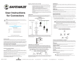
If the connecting element that a snap hook (shown) or carabiner attaches to is undersized or irregular in
shape, a situation could occur where the connecting element applies a force to the gate of the snap hook
or carabiner. This force may cause the gate (of either a self-locking or a non-locking snap hook) to open,
allowing the snap hook or carabiner to disengage from the connecting point.
1. Force is applied to the
snap hook.
2. The gate presses against the
connecting ring.
3. The gate opens allowing the
snap hook to slip off.
Small ring or other
non-compatibly
shaped element
Figure 2 - Unintentional Disengagement (Roll-out)

3
Connectors (hooks, carabiners, and D-rings) must be capable of supporting at least 5,000 lbs. (22.2 kN).
Connectors must be compatible with the anchorage or other system components. Do not use equipment
that is not compatible. Non-compatible connectors may unintentionally disengage. See Figure 2. Connectors
must be compatible in size, shape, and strength. Self locking snap hooks and carabiners are required by
ANSI Z359.1 and OSHA.
2.3 MAKING CONNECTIONS: Only use self-locking snap hooks and carabiners with this equipment. Only use
connectors that are suitable to each application. Ensure all connections are compatible in size, shape and
strength. Do not use equipment that is not compatible. Ensure all connectors are fully closed and locked.
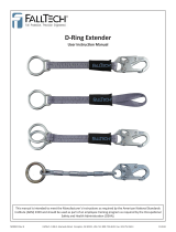
DBI‑SALA connectors (snap hooks and carabiners) are designed to be used only as specied in each
product’s user’s instructions. See Figure 3 for inappropriate connections. DBI-SALA snap hooks and
carabiners should not be connected:
A. To a D-ring to which
another connector is
attached.
B. In a manner that
would result in a load
on the gate.
NOTe: Large throat opening
snap hooks should not be
connected to standard size
D‑rings or similar objects
which will result in a load on
the gate if the hook or D‑ring
twists or rotates. Large throat
snap hooks are designed
for use on xed structural
elements such as rebar or
cross members that are not
shaped in a way that can
capture the gate of the hook.
C. In a false engagement, where features that protrude from the snap hook or carabiner catch on the
anchor and without visual confirmation seems to be fully engaged to the anchor point.
D. To each other.
E. Directly to webbing or rope lanyard or tie-back (unless the manufacturer’s instructions for both the
lanyard and connector specifically allow such a connection).
F. To any object which is shaped or dimensioned such that the snap hook or carabiner will not close and
lock, or that roll-out could occur.
2.4 ANCHORAGE STRENGTH: Anchorages selected for personal fall arrest systems (PFAS) shall have a
strength capable of sustaining static loads, applied in the directions permitted by the PFAS, of at least: (A)
3,600 lbs. (16 kN) when certication exists (Reference ANSI Z359.1 for certication denition), or (B) 5,000
lbs. (22.2 kN) in the absence of certication. When more than one PFAS is attached to an anchorage (ie.
I-beam, etc..), the anchorage strengths set forth in (A) and (B) above shall be multiplied by the number of
personal fall arrest systems attached to the anchorage.
3.0 OPeRATION AND USAGe:
WARNING: Do not alter or intentionally misuse this equipment. Consult DBI‑SALA when using this equipment in
combination with other components or subsystems other than those described in this manual. Some subsystem
and component combinations may interfere with the proper operation of this equipment. Use caution when using
this equipment around moving machinery and electrical hazards. Use caution when using this equipment around
sharp edges and chemical hazards.
WARNING: Consult your doctor if there is any reason to doubt your tness to safely absorb the shock from a fall
arrest. Age and tness seriously affect a workers ability to withstand falls. Pregnant women or minors must not
use DBI‑SALA parapet wall anchors.
Figure 3 - Inappropriate Connections

4
3.1 BEFORE EACH USE of this equipment, carefully inspect it to assure that it is in serviceable condition. Check
for worn or damaged parts; ensure all hardware is present and secure and is not distorted, or have any
sharp edges, burrs, cracks, or corrosion. Refer to section 5.0 for further inspection details. Do not use this
equipment if inspection reveals an unsafe condition.
3.2 PLAN your fall arrest system before starting work. Take into consideration factors that affect your safety at
any time during use. The following list gives some important points to consider when planning your system:
A. ANCHORAGE: Select an anchorage point that is rigid and capable of supporting the required loads. See
section 2.4.
B. FREE FALL: Personal fall arrest systems must be rigged to limit any free fall to a maximum of 6 feet
(1.8 m) (Federal Law and ANSI Z359.1). Avoid working above your anchorage level since an increased
free fall distance will result. Consult DBI-SALA for maximum free fall distances for applications other
than fall arrest.
C. SYSTEM PERFORMANCE: The parapet wall anchor must be used in combination with either a shock
absorbing lanyard or a self retracting lifeline that will limit the maximum fall arrest forces to 1800 lbs.
D. FALL CLEARANCE: Should a fall occur, there must be sufficient clearance in the fall area to arrest the
fall before striking the ground or other object. The actual clearance required is dependent upon the type
of fall arrester connecting subsystem used (shock absorbing lanyard or self retracting lifeline). Energy
Absorbing Lanyards can extend the fall arrest distance by up to 42 inches (1.07 m).
E. SWING FALLS: Swing falls occur when the anchorage point is not directly above the point where a fall
occurs. See Figure 4. The force of striking an object while swinging can be great and may cause serious
injury. Swing falls can be minimized by working as directly below the anchorage as possible. Do not
work at more than a 30 degree angle from vertical below the parapet wall anchor, working beyond this
range could create a swing fall situation. See Figure 5.
F. SHARP EDGES: Avoid working where the connecting subsystem
(ie. shock absorbing lanyard, self retracting lifeline, full body
harness, etc.) or other system components will be in contact with,
or abrade against, unprotected sharp edges. If working with this
equipment near sharp edges is unavoidable, protection against
cutting must be provided by using a heavy pad or other means
over the exposed sharp edge.
G. RESCUE: Should a fall occur, the user (employer) must have a
rescue plan and the means at hand to implement it.
H. AFTER A FALL: Any equipment which has been subjected to
the forces of arresting a fall must be removed from service
immediately and destroyed or sent to a factory authorized service
center for repair.
I. ABUSE: Avoid dropping the parapet wall anchor from a height or
allowing it to strike against a structure which could damage it.
J. FOREIGN ELEMENTS: Avoid contaminating the equipment with
paints, cement or other materials which could adversely effect the
performance of the product.
3.3 INSTALLATION REQUIREMENTS:
A. SUPERVISION: It is recommended that this
equipment is installed under the supervision of
a qualified person as defined by OSHA 1910.66
Appendix C.
B. ANCHORAGE CONNECTOR LOCATION:
Select an anchorage with suitable anchorage
strength requirements (see section 2.4) which
will provide the best overall safety to the user.
The following are some considerations that
must be made when choosing an anchorage
location: the wall on which the Parapet Wall
Figure 4 - Swing Falls
Figure 5 - Working Range of Anchor
30° 30°
30°
14 1/2 inches
(36.8 cm)
Maximum Parapet wall thickness

5
Anchors is to be installed may be a maximum of 14.5 inches (36.8 cm) thick and must meet the
strength requirements specified in section 2.4, the location must be safely accessible when connecting
to or disconnecting from the anchor, swing falls should not be permitted if injury could occur should the
user fall, the location must be free of other equipment or moving parts, there must be adequate total
fall clearance, and there must be a rescue means. The anchorage must allow the parapet wall anchor
to hang in a vertical orientation. Do not install the parapet wall anchor on an incline, at an angle, or
upside-down. See Figure 6.
C. INSTALLATION: (See Figure 1 for referenced parts). Unscrew the set screws so the points do not
protrude into the anchor slot. Remove the detent pin and move the adjustable arm back far enough to
allow the clamp to fit over the parapet wall. Make sure the top surface within the anchor slot is fully
seated on the parapet wall. Slide the adjustable arm toward the parapet wall and reinsert the detent pin
through the appropriate position setting holes. Tighten each set screw until it makes contact with the
parapet wall. Hand tighten the screws until snug. Excessive torque can damage the parapet wall or the
parapet wall anchor.
WARNING: Read and follow manufacturer’s instructions for associated equipment (ie. full body harness, shock
absorbing lanyard, self retracting lifeline, etc.) used in your personal fall arrest system.
3.4 MAKING CONNECTIONS: When connecting to the parapet wall anchor self-locking snap hooks or self-
locking and self-closing gate carabiners must be used to reduce the possibility of roll-out. Do not use
hooks or connectors that will not completely close over the attachment object. Do not use non-locking snap
hooks. Always follow the manufacturer’s instructions supplied with each system component.
3.5 CONNECTING TO THE PARAPET WALL ANCHOR: The parapet wall anchor is an anchorage connector
for a shock absorbing lanyard or a self retracting lifeline. Contact DBI-SALA for information regarding
other possible connecting subsystems. Make sure the connector (ie. self-locking snap hook of lanyard) is
fully engaged and locked onto the back D-ring (dorsal) of the body support. Make sure connections are
compatible (size, shape, strength, etc.).
If connecting a shock absorbing lanyard to the parapet wall anchor, follow the above instructions to connect
one end of lanyard (shock absorber pack end) to body support and connect the other end to the parapet
wall anchor making sure the self-locking snap hook is fully engaged and locked onto the D-ring.
If using a self retracting lifeline, it must be connected to the D-ring with a self-locking and self-closiing
carabiner (attach the carabiner to the anchorage location on SRL), the self retracting lifeline must hang
vertically. Then connect the lifeline end of the SRL to the body support (harness). Make sure the connector
(ie. self-locking snap hook, carabiner) is fully engaged and locked onto the anchorage connector, SRL and
body support. Make sure connections are compatible (size, shape, strength, etc.).
WARNING: When attaching a self retracting lifeline to a parapet wall anchor, make certain the SRL hangs
vertically and freely (not at an angle).
If installing a horizontal lifeline, follow the manufacturer’s instructions for installation and use provided with
the horizontal lifeline system.
Figure 6 - Installing the Parapet Wall Anchor

6
4.0 TRAINING:
4.1 It is the responsibility of the user and the purchaser of this equipment to assure they are familiar with
these instructions, trained in the correct care and use of, and are aware of the operating characteristics,
application limits and the consequences of improper use of this equipment.
IMPORTANT: Training must be conducted without exposing the trainee to a fall hazard. Training should be
repeated on a periodic basis.
5.0 INSPeCTION:
5.1 FREQUENCY
• Before each use, visually inspect per steps listed in section 5.2 and 5.3.
• This equipment must be inspected by a competent person other than the user at least annually. See section
5.2 and 5.3 for guidelines. Record the results of each formal inspection in the inspection log in section 10.0.
IMPORTANT: Extreme working conditions (harsh environments, prolong use, etc.) may require increasing the
frequency of inspections.
IMPORTANT: If this equipment has been subjected to forces resulting from the arrest of a fall, it must be
immediately removed from service and destroyed or returned to DBI‑SALA for possible repair. See section 5.2.
5.2 INSPECTION STEPS
Step 1. Inspect the parapet wall anchor for physical damage. Look carefully for any signs of cracks,
dents or deformities in the metal.
Step 2. Inspect the parapet wall anchor for signs of excessive corrosion.
Step 3. Ensure that the working parts are free from excessive dirt, oil, or other build-up.
Step 4. Inspect the D‑ring, xed arm, and fasteners. The D‑ring must be free of cracks, dents or deformities
in the metal. The xed arm and bolt holding the D‑ring must be undamaged and the nut fastened
tightly to the bolt.
Step 5. Inspect the points of the set screws. The points must not be broken and must be sharp enough to
bite into a mild parapet wall.
Step 6. Inspect the detent pin to ensure that it inserts fully through the position setting holes of the arms.
Step 6. Inspect labels, all labels should be present and fully legible. See section 9.0. Labels must be
replaced if illegible or missing.
Step 7. Inspect each system component or subsystem per associated manufacturer’s instructions.
Step 8. Record the inspection date and results in the inspection log. See section 10.0.
5.3 If inspection reveals a defective condition, remove the unit from service immediately and destroy or contact
a factory authorized service center for repair.
NOTe: Only DBI‑SALA or parties authorized in writing may make repairs to this equipment.
6.0 MAINTeNANCe - SeRVICING - STORAGe:
6.1 Clean the anchorage connector (parapet wall anchor) with mild soap detergent solution and rinse. The
working parts may be sprayed sparingly with a moisture repelling agent. Excessive build-up of dirt, paint,
etc. may prevent the anchorage connector from working properly.
6.2 If you have any questions concerning the condition of your parapet wall anchor or have any doubt about
putting it into service contact DBI-SALA immediately.

7
7.0 SPeCIfICATIONS:
7.1 MATERIALS:
• Material: Zinc Plated Steel
• Minimum Breaking Strength: 5,000 lbs. (22.2 kN)
• Maximum Capacity: 310 lbs. (141 kg) (one person)
• Weight: 28 lbs. (12.7 kg)
• Parapet Wall Thickness: Up to 14.5 inches (36.8 cm)
7.2 DIMENSIONS:
8.0 TeRMINOLOGY
AUTHORIZED PERSON: A person assigned by the employer to perform duties at a location where the person
will be exposed to a fall hazard ( otherwise referred to as “user” for the purpose of these instructions).
RESCUER: Person or persons other than the rescue subject acting to perform an assisted rescue by
operation of a rescue system.
CERTIFIED ANCHORAGE: An anchorage for fall arrest, positioning, restraint, or rescue systems that a
qualified person certifies to be capable of supporting the potential fall forces that could be encountered
during a fall or that meet the criteria for a certified anchorage prescribed in this standard.
QUALIFIED PERSON: A person with a recognized degree or professional certificate and with extensive
knowledge, training, and experience in the fall protection and rescue field who is capable of designing,
analyzing, evaluating and specifying fall protection and rescue systems to the extent required by this
standard.
COMPETENT PERSON: One who is capable of identifying existing and predictable hazards in the surroundings
or working conditions which are unsanitary, hazardous, or dangerous to employees, and who has
authorization to take prompt corrective measures to eliminate them.
22.00
15.00
3.00
5.50
5.25

8
9.0 LABeLS
9.1 The following labels must be present and fully legible:
ENGLISH WARNING LABEL
FRENCH WARNING LABEL
LOADING DIRECTION LABEL

9
SPECIFICATION, INSPECION
AND USE LABEL
9.1 Continued . . .

10
INSPECTION DATE INSPECTION ITEMS
NOTED
CORRECTIVE ACTION MAINTENANCE
PERFORMED
Approved by:
Approved by:
Approved by:
Approved by:
Approved by:
Approved by:
Approved by:
Approved by:
Approved by:
Approved by:
Approved by:
Approved by:
Approved by:
Approved by:
Approved by:
Approved by:
Approved by:
Approved by:
Approved by:
9.0 INSPeCTION AND MAINTeNANCe LOG
DATE OF MANUFACTURE
MODEL NUMBER
DATE OF PURCHASE

11
INSPECTION DATE INSPECTION ITEMS
NOTED
CORRECTIVE ACTION MAINTENANCE
PERFORMED
Approved by:
Approved by:
Approved by:
Approved by:
Approved by:
Approved by:
Approved by:
Approved by:
Approved by:
Approved by:
Approved by:
Approved by:
Approved by:
Approved by:
Approved by:
Approved by:
Approved by:
Approved by:
Approved by:
9.0 INSPeCTION AND MAINTeNANCe LOG
DATE OF MANUFACTURE
MODEL NUMBER
DATE OF PURCHASE

12
USA Canada
3833 SALA Way 260 Export Boulevard
Red Wing, MN 55066-5005 Mississauga, Ontario L5S 1Y9
Toll Free: 800-328-6146 Toll Free: 800-387-7484
Phone: (651) 388-8282 Phone: (905) 795-9333
Fax: (651) 388-5065 Fax: (905) 795-8777
Email: solutions@capitalsafety.com Email: solutions@capitalsafety.com
www.capital safety.com www.capital safety.com
This manual is available for download at www.capital safety.com.
Form: 5902395
Rev: A
I S O
9 0 0 1
Certicate No. FM 39709
A Capital Safety Company
/