Page is loading ...

© Copyright 2010, DB Industries, Inc.
FORM NO: 5903088 REV: B
PRO-Line™
Web Horizontal Lifeline System
This manual is intended to be used as part of an
employee training program as required by OSHA.
Models: 1200101, 1200105
A Capital
Safety
Brand
WARNING: This product is part of a personal
fall arrest system. The user must follow the
manufacturer’s instructions for each component of
the system. These instructions must be provided
to the user of this equipment. The user must
read and understand these instructions before
using this equipment. Manufacturer’s instructions
must be followed for proper use and maintenance
of this equipment. Alterations or misuse of this
equipment, or failure to follow instructions, may
result in serious injury or death.
IMPORTANT: Record the product
identifi cation information from the ID label in the
inspection and maintenance log in this manual.
IMPORTANT: OSHA regulations state that
horizontal lifelines shall be installed and used under
the supervision of a qualifi ed person (see below
for defi nition) as part of a complete personal fall
arrest system that maintains a safety factor of at
least two.
QUALIFIED PERSON: An individual with
a recognized degree or professional certifi cate,
and extensive knowledge and experience in the
subject fi eld, who is capable of design, analysis,
evaluation, and specifi cation in the subject work,
project, or product. Refer to OSHA 1910.66,
1926.32, and 1926.502.
PURPOSE: The Web Horizontal Lifeline System is
designed for use as an anchoring means for one or
two persons. Use the Web Horizontal Lifeline System
where horizontal mobility and fall protection are
required.
LIMITATIONS: The following limits apply to the
installation and use of the Web Horizontal Lifeline
System. Other limitations may apply:
IMPORTANT: If you have questions on the
use, care, or suitability of this equipment for your
application, contact Capital Safety.
HORIZONTAL LIFELINE SPAN: The maximum span
distance is 60 feet. The span length must be reduced
when clearance is limited.
ANCHORAGES: The Web horizontal lifeline must be
installed on anchorages that meet the requirements.
SYSTEM CAPACITY: The maximum capacity of the
Web horizontal lifeline is two persons. The maximum
weight of each person, including tools and clothing, is
310 lbs. (141kg).
CONNECTING SUBSYSTEM: Each person’s
connecting subsystem must limit fall arrest forces to
900 lbs. (4kN) or less.
FREE FALL: Rig and use the personal fall arrest
system such that the maximum potential free
fall does not exceed Government regulatory and
subsystem manufacturer’s requirements. See
subsystem manufacturer’s instructions for more
information.
SWING FALLS: See Figure 2. Swing falls occur
when the anchorage point is not directly overhead.
The force of striking an object in a swing fall may
cause serious injury or death. Minimize swing falls
by working as directly below the anchorage point as
possible. Do not permit a swing fall if injury could
occur. Swing falls will signifi cantly increase the
clearance required when a self retracting lifeline or
other variable length connecting subsystem is used. If
a swing fall situation exists in your application, contact
Capital Safety before proceeding.
Figure 2
Swing Fall Hazard
FALL CLEARANCE: There must be suffi cient clearance
below the worker to arrest a fall before striking the
lower level or obstruction.
BODY SUPPORT: A full body harness must be used
with the Web Horizontal Lifeline System.
ENVIRONMENTAL HAZARDS: Use of this equipment
in areas with environmental hazards may require
additional precautions to reduce the possibility of
injury to the user or damage to the equipment.
Hazards may include, but are not limited to; heat,
chemicals, corrosive environments, high voltage power
lines, gases, moving machinery, and sharp edges.
Contact Capital Safety if you have questions about
using this equipment where environmental hazards
exist.
TRAINING: This equipment must be installed and
used by
persons trained in its correct application and
use.
APPLICABLE STANDARDS: Refer to national
standards, including ANSI Z359.1, local, state, and
federal (OSHA 1910.66 and 1926.502) requirements
for more information on personal fall arrest systems
and associated components. In Canada, see the Z259
group of CSA standards.
PERSONAL FALL ARREST SYSTEM COMPONENTS:
The Web horizontal lifeline must be used with Capital
Safety approved components and subsystems. Non-
approved components may be incompatible, and
could affect the safety and reliability of the complete
system. Personal fall arrest components used with
this system must meet all applicable OSHA and ANSI
requirements. A full body harness must be used with
this system.
PERSONAL FALL ARREST SYSTEM CONNECTORS:
Connectors used to attach to the attachment O-ring
on the horizontal lifeline (hooks, carabiners, D-rings)
must support at least 5,000 lbs. Connectors and
attachment elements must be compatible in size,
shape, and strength. Non-compatible connectors may
unintentionally disengage (roll-out). Do not use non-
locking connectors with this system.
ANCHORAGE CONNECTORS: Connectors used to
attach the horizontal lifeline to end anchors must be
compatible with the connection point. The connection
must be positive; and, with connecting elements,
capable of sustaining a 5,000 lbs. (22.2kN) load
without failure.
STRUCTURE LOAD: Structural anchorage points
must be rigid,
and capable of supporting at least 3,600
lbs. (16kN) along the axis of the horizontal lifeline.
Anchorages must also support at least 3,600 lbs. (16kN)
applied in all potential directions of fall arrest that are
perpendicular to the axis of the horizontal lifeline.
WARNING: Anchorages must be rigid. Large
deformations of the anchorage will affect system
performance, and may increase the required fall
clearance below the system, which could result in
serious injury or death.
Connecting Subsystem: The connecting subsystem
is the portion of the personal fall arrest system that
is used to connect between the horizontal lifeline
subsystem and harness fall arrest attachment
element. The connecting subsystem must limit forces
applied to the horizontal lifeline to 900 lbs. (4kN) or
less.
WARNING: Do not alter or intentionally misuse
this equipment. Consult Capital Safety when using
this equipment in combination with components
or subsystems other than those described in
this manual. Some subsystem and component
combinations may interfere with the operation of this
equipment. Use caution when using this equipment
around moving machinery, electrical hazards,
chemical hazards, and sharp edges.
WARNING: Consult your doctor if there is
reason to doubt your fi tness to absorb the impact
from a fall arrest. Age and fi tness can affect your
ability to withstand fall arrest forces. Pregnant
women and minors must not use this system.
BEFORE EACH USE inspect this equipment. Do not
use this equipment if inspection reveals an unsafe or
defective condition. Plan your use of the fall protection
system prior to exposing workers to dangerous
situations. Consider all factors affecting your safety
before using this system.
Read and understand all
manufacturer’s instructions for each component of the
personal fall arrest system. All Capital Safety harnesses
and connecting subsystems are supplied with separate
user instructions. Keep all instructions for future
reference.
Review these instructions to ensure system limitations
and other requirements have been adhered to. Review
applicable information regarding system clearance
Figure 1
Typical Web Horizontal Lifeline Installation
Span length 60 ft. max.
(18.29 m)
In-line Engery Absorber
Carabiner
Attachment
O-ring for
user
(Lanyard)
Ratchet Tensioner
Tie-off Adapter
(Anchorage
Connector)

2
criteria, and ensure changes have not been made to
the system installation (i.e. length) or occurred at the
job site that could affect the required fall clearance.
Do not use the system if changes are required.
SYSTEM INSTALLATION: Figure 1 shows a typical
Web horizontal lifeline installation. When using an
energy absorbing lanyard to connect to the system,
the end anchorages must be located at a height
which will limit the free fall to 6 feet (1.8m). When
using a self retracting lifeline (SRL) to connect to the
system, the end anchorages must be located above
the user. The SRL, when fully retracted, must be
above the harness attachment level. The horizontal
lifeline system should be positioned at a level that
will minimize free fall while allowing ease of use.
The horizontal lifeline should be positioned near
the work location to minimize swing fall hazards.
The connecting subsystem length should be kept as
short as possible to reduce the potential free fall and
required clearance distance. Both anchorages must
be installed at approximately the same elevation, so
that the horizontal lifeline system is not sloped more
than 5°.
Determine the locations of the end anchorages and
evaluate their strengths. Determine the span length
and evaluate the required clearance using Figures 5,
6, or 7 and Tables 1, 2 or 3.
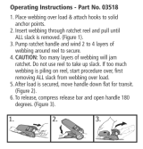
Figure 3
Wrap tie-off adaptor twice
around anchorage structure
Tie-off adapter
Vertical or sloped
anchorage structure
Installing Tie-off Adapter to Vertical or Sloped
Anchorage Structure
Install the anchorage connectors. The Web Horizontal
Lifeline System includes two tie-off adaptor anchorage
connectors. To ensure the tie-off adaptor does not
slide down a vertical or sloped anchorage, the tie-off
adaptor must be wrapped twice around the structure
as shown in Figure 3. Refer to the tie-off adaptor
instructions for complete installation information.
The horizontal lifeline may be secured directly to
the anchorage when the anchorage incorporates
a compatible attachment
element that meets the
requirements.
Secure each end of the horizontal lifeline to the
anchorage connectors with the snap hook or carabiner.
Installation Tip: When attaching to the tie-off adaptor,
connect carrying bag through handle to secure bag
to the end of the system. Note: Bag handle is not to
be used as an anchorage connector, only to be held in
place by passing the connection through the handle.
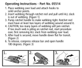
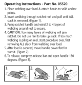
Remove the slack from the horizontal lifeline by
pulling the web through the ratchet tensioner by
hand. Once the line is pulled through the adjuster
as tight as possible by hand, activate the ratchet by
rotating the handle back and forth in a 180 degree arc
to tension the webbing line tight.
PLEASE NOTE: There is no in-line tension
indicator and it is recommended that the operator
tension the ratchet with one hand only on the
handle, and with no external parts be used to
further tighten the line. Normal working tension is
achieved by a one-handed operation will tension
the webbing line satisfactorily.
Installation Tip: When wound onto the central
hub during tensioning, the webbing should have a
minimum of 1.5 times the revolution of the ratchet
hub. Should the webbing over fi ll the ratchet, it can
jam requiring the operator to release the line and
start again.
Once tensioned, the ratchet handle must be pushed
to the closed and locked position. Surplus webbing
should be folded and placed in the bag if attached or
near the end of the system away from center work
area.
PERSONAL FALL ARREST SYSTEM COMPONENTS:
Inspect and don the full body harness according to
manufacturer’s instructions. Attach the connecting
subsystem (energy absorbing lanyard or SRL) to the
dorsal connection on the harness.
Figure 4
Anchorage Strength Requirements
3,600 lbs. Minimum
(16.0 kN)
3,600 lbs. Minimum
(16.0 kN)
3,600 lbs. (16.0 kN) Minimum (in all potential directions of fall
arrest that are perpendicular to axis of lifeline)
Figure 5
Clearance Evaluation for One Worker
Connected to the System with a Capital
Safety Energy Absorbing Lanyard
Required clearance from nearest Lower
Level or Obstruction to Horizontal
Lifeline System Height:
1. Find your system span length in
Table 1.
2. Find your lanyard length in Table 1
3. The required clearance is where
the span length and lanyard length
intersect
Span Length
Energy
Absorbing
Lanyard
Working
Level
Lower Level
or Obstruction
Figure 6
Clearance Evaluation for Two Workers
Connected to the System with a
Capital Safety Energy Absorbing
Lanyard
Required clearance from the nearest
Lower Level or Obstruction to
Horizontal Lifeline System Height
1. Find your system length in Table
2
2. Find your lanyard length in Table
2
3. The required clearance is where
the span length and lanyard
length intersect
Span Length
Energy Absorbing
Lanyard
Lower Level or
Obstruction
Working
Level
Figure 7
Clearance Evaluation for One or Two
Workers Connected to the System
with a Captial Safety Self-Retracting
Lifeline
Required clearance from nearest
Lower Level or Obstruction to working
level:
1. Find your system span length in
Table 3
2. Find the number of workers to be
connected to the system
3. The required clearance is where
the span length and number of
workers intersect
WARNING:This information only
applies when the SRL is directly
over head and above the level of the
harness attachment point, and the
user is standing.
Span Length
Self-Retracting Lifeline
Working
Level
Lower Level
or Obstruction

3
Table 1
Required clearance for one worker connected to
the system with a Capital Safety Energy Absorbing
Lanyard (C.S.E.A.L.) (See Figure 5)
Span length
in feet (m)
Length of Energy Absorbing Lanyard
in feet (m)
3’
(.91)
4’
(1.22)
5’
(1.52)
6’
(1.82)
0-10
(0-3.05)
18’
(5.49)
19’
(5.79)
20’
(6.09)
21’
(6.40)
10-15
(3.05-4.57)
18’-6”
(5.63)
19’-6”
(5.94)
20’-6”
(6.25)
21’-6”
(6.55)
15-20
(4.57-6.10)
19’-2”
(5.84)
20’-2”
(6.14)
21’-2”
(6.45)
22’-2”
(6.75)
20-25
(6.10-7.62)
19’-9”
(6.01)
20’-9”
(6.32)
21’-9”
(6.63)
22’-9”
(6.93)
25-30
(7.62-9.14)
20’-5”
(6.22)
21’-5”
(6.52)
22’-5”
(6.83)
23’-5”
(7.14)
30-35
(9.14-
10.67)
21’-2”
(6.45)
22’-2”
(6.76)
23’-2”
(7.06)
24’-2”
(7.36)
35-40
(10.67-
12.19)
22’-5”
(6.83)
23’-5”
(7.13)
24’-5”
(7.44)
25’-5”
(7.75)
40-45
(12.19-
13.72)
23’-2”
(7.06)
24’-2”
(7.36)
25’-2”
(7.67)
26’-2”
(7.98)
45-50
(13.72-
15.24)
23’-8”
(7.21)
24’-8”
(7.52)
25’-8”
(7.82)
26’-8”
(8.13)
50-55
(15.2-
16.76)
24’-5”
(7.44)
25’-5”
(7.75)
26’-5”
(8.05)
27’-5”
(8.36)
55-60
(16.76-
18.29)
25’-1”
(7.65)
26’-1”
(7.95)
27’-1”
(8.25)
28’-1”
(8.56)
Table 2
Required clearance for two workers connected to the
system with a C.S.E.A.L. (See Figure 6).
Span
length
in feet
(m)
Length of Energy Absorbing Lanyard
in feet (m)
3’
(.91)
4’
(1.22)
5’
(1.52)
6’
(1.82)
0-10
(0-3.05)
19’
(5.79)
20’
(6.09)
21’
(6.40)
22’
(6.70)
10-15
(3.05-
4.57)
20’-3”
(6.17)
21’-3”
(6.48)
22’-3”
(6.78)
23’-3”
(7.09)
15-20
(4.57-
6.10)
21’-8”
(6.60)
22’-8”
(6.90)
23’-8”
(7.21)
24’-8”
(7.51)
20-25
(6.10-
7.62)
23’-2”
(7.06)
24’-2”
(7.36)
25’-2”
(7.67)
26’-2”
(7.98)
25-30
(7.62-
9.14)
24’-7”
(7.49)
25’-7”
(7.80)
26’-7”
(8.10)
27’-7”
(8.41)
30-35
(9.14-
10.67)
26’
(7.92)
27’
(8.22)
28’
(8.53)
29’
(8.83)
35-40
(10.67-
12.19)
27’-5”
(8.36)
28’-5”
(8.66)
29’-5”
(8.97)
30’-5”
(9.27)
40-45
(12.19-
13.72)
28’-9”
(8.76)
29’-9”
(9.06)
30’-9”
(9.37)
31’-9”
(9.68)
45-50
(13.72-
15.24)
30’-4”
(9.25)
31’-4”
(9.55)
32’-4”
(9.86)
33’-4”
(10.16)
50-55
(15.24-
16.76)
31’-8”
(9.70)
32’-8”
(9.96)
33’-8”
(10.26)
34’-8”
(10.57)
55-60
(16.76-
18.29)
33’-2”
(10.10)
34’-2”
(10.41)
35’-2”
(10.71)
36’-2”
(11.02)
Table 3
Required clearance for one or two workers
connected to the system with a Self-Retracting
Lifeline (See Figure 7).
Span length
in feet (m)
Required
clearance
below working
level for one
worker
Required
clearance
below working
level for two
workers
0-10
(0-3.05)
10’-9”
(3.27)
14’-9”
(4.49)
10-15
(3.05-4.57)
11’-3”
(3.43)
15’-4”
(4.67)
15-20
(4.57-6.10)
11’-7”
(3.53)
15’-8”
(4.77)
20-25
(6.10-7.62)
12’-1”
(3.68)
16’-3”
(4.95)
25-30
(7.62-9.14)
12’-6”
(3.81)
16’-7”
(5.06)
30-35
(9.14-10.67)
13’-7”
(4.14)
17’-6”
(5.33)
35-40
(10.67-12.19)
14’-8”
(4.47)
18’-2”
(5.53)
40-45
(12.19-13.72)
15’-9”
(4.80)
19’-3”
(5.86)
45-50
(13.72-15.24)
17’
(5.18)
20’-4”
(6.20)
50-55
(15.24-16.76)
18’-1”
(5.51)
21’-5”
(6.53)
55-60
(16.76-18.29)
19’-2”
(5.84)
22’-6”
(7.08)
CONNECTING TO THE HORIZONTAL LIFELINE
SYSTEM: Approach the work area using the
appropriate access equipment. Connect your personal
fall arrest system to one of the attachment O-rings
on the horizontal lifeline. Connectors must meet all
compatibility and strength requirements.
HAZARDOUS SITUATIONS: Do not take
unnecessary risks, such as jumping or reaching too
far from the edge of the working surface. Do not allow
the connecting subsystem to pass under arms or
between feet. To avoid inadequate clearance, do not
climb above the horizontal lifeline. To avoid swing fall
hazards, do not work too far from either side of the
horizontal lifeline.
TWO (2) PERSONS CONNECTED TO THE HLL:
When a person falls while connected to the horizontal
lifeline, the system will defl ect. If two (2) persons are
connected to the same horizontal lifeline, and one (1)
person falls, the second person may be pulled off the
working surface due to defl ection. The potential for
the second person falling increases as the horizontal
lifeline span length increases. The use of independent
horizontal lifeline systems for each person, or shorter
span length, is recommended to minimize the
potential of the second person falling.
FREE FALL: The personal fall arrest system must be
rigged to limit free falls to 6 feet (1.8m) or less when
using an energy absorbing lanyard, or such that the
SRL is overhead without slack, according to OSHA
requirements.
SHARP EDGES: Avoid working where the connecting
subsystem or other system components will be in
contact with, or abrade against, unprotected sharp
edges. If working around sharp edges is unavoidable,
a protective cover must be used to prevent cutting of
the personal fall arrest system components.
IN THE EVENT OF A FALL: The responsible party
must have a rescue plan and the ability to implement
a rescue. Tolerable suspension time in a full body
harness is limited, so a prompt rescue is critical.
RESCUE: With the number of potential scenarios for
a worker requiring rescue, an on-site rescue team is
benefi
cial. The rescue team is given the tools, both
in equipment and technique, to perform a successful
rescue. Training should be provided on a periodic basis
to ensure rescuers’ profi ciency.
SYSTEM REMOVAL: When no longer required, the
horizontal lifeline system should be removed from the
job site. Release tension on the horizontal lifeline:
Pull on the release lever under the handle on the
ratchet tensioner and open the handle fully. This will
release the lock and allow the webbing safety line to
rotate within the hub. Remove the webbing safety
line from the anchorage points and roll the webbing
up from the long end towards the center. Fold all
the parts of the webbing line into the storage bag
including the instructions and close.
It is the responsibility of all users of this equipment
to understand these instructions, and to be trained in
the correct installation, use, and maintenance of this
equipment. These individuals must be aware of the
consequences of improper installation or use of this
equipment. This user manual is not a substitute for
a comprehensive training program. Training must be
provided on a periodic basis to ensure profi ciency of
the users.
BEFORE EACH INSTALLATION: Inspect all
system components according to these or other
manufacturer’s instructions. System components must
be formally inspected by a qualifi ed person, other
than the user, at least annually. Formal inspections
should concentrate on visible signs of deterioration or
damage to the system components. Items found to be
defective must be replaced. Do not use components
if inspection reveals an unsafe or defective condition.
Record results of each inspection in the inspection and
maintenance log of this manual.
INSTALLED SYSTEMS: An inspection of the
horizontal lifeline system by a qualifi ed person must
be conducted after the system is installed. The
system must be periodically inspected by a qualifi ed
person when left installed for an extended period, and
prior to each day’s use. Periodic inspections should
be performed at least monthly, or more frequently
when site conditions and use warrant. Inspections of
installed systems should include the inspection steps
listed.
BEFORE SYSTEM USE:
Inspect all metal components (hooks, O-rings, ratchet
tensioner, etc.) for cracks, deformities, corrosion,
or other damage that may affect their strength or
operation. Inspect webbing for cuts, edge wear
tears, burns, abrasion, and chemical contamination.
Webbing abrasion over the edges whilst under tension
may cause damage to outer fi bres leading to possible
failure. Inspect system labels. The labels must be
present and fully legible.
IMPORTANT: If this equipment is subjected
to the forces of a fall arrest, it must be removed
from service and destroyed.
If inspection reveals an unsafe or defective condition,
remove unit from service and destroy.
USER EQUIPMENT: Inspect harness and energy
absorbing lanyard or SRL according to manufacturer’s
instruction.
CLEANING AND MAINTENANCE: Clean the Web
horizontal lifeline system with water and a mild
detergent. Wipe dry with a clean, dry cloth and hang
to air dry. Do not force dry with heat. An excessive
build-up of dirt, paint, etc. may prevent the system
from working properly, and in severe cases, weaken
the web.
STORAGE: Store this horizontal lifeline system in a
clean, dry environment, out of direct sunlight. Avoid
areas where chemical vapors are present. Thoroughly
inspect the system after extended storage.
USER EQUIPMENT: Maintain, service, and store user
equipment according to manufacturer’s instructions.
Materials
Ratchet
Tensioner
Steel, plated
O-rings Alloy steel, plated
Snap Hooks Alloy steel, plated
Carabiners High tensile alloy steel, plated
Tie-off Adaptor Polyester web, plated alloy
steel hardware
Web Lifeline Polyester, 12,000 lb breaking
strength

4
A Capital Safety Brand
This manual is available for download at
www.capitalsafety.com.
Certificate No. FM 39709
ISO
9001
INSPECTION AND MAINTENANCE LOG
SERIAL NUMBER:
MODEL NUMBER:
DATE PURCHASED: DATE OF FIRST USE:
INSPECTION DATE INSPECTION ITEMS
NOTED
CORRECTIVE ACTION MAINTENANCE
PERFORMED
Approved By:
Approved By:
Approved By:
Approved By:
Approved By:
These labels must be present and fully legible.
USA Canada
3833 SALA Way 260 Export Boulevard
Red Wing, MN 55066-5005 Mississauga, Ontario L5S 1Y9
Toll Free: 800-328-6146 Toll Free: 800-387-7484
Phone: (651) 388-8282 Phone: (905) 795-9333
Fax: (651) 388-5065 Fax: (905) 795-8777
www.capitalsafety.com www.capitalsafety.com
/