Page is loading ...

99627
A DIVISION OF DOUGLAS DYNAMICS, LLC
Accessory Harness & Enclosure Kit
Stainless Steel Hopper Spreader – Hydraulic
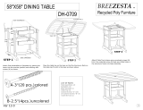
PARTS LIST
99627 Accessory Harness & Enclosure Kit
Item Part Qty Description Item Part Qty Description
198994 1Accessory Enclosure, Hydraulic ns 99738 1Accessory Cable Assy – Hopper Side
298988 1 Dash Bracket Kit ns 99737 1Accessory Cable Assy – Vehicle Side
399109 4Rocker Switch ns 78390 1Accessory Switch Harness Assembly
ns 1 Bolt Bag – Accessory Harness Kit ns 22511K 1 22" Battery Cable – Red
Item 1 98994 Accessory Enclosure – Hydraulic
4 1 Accessory Enclosure Cover 7 4 1/4‑20 x 3/4 Hex Cap Screw SS
5 1 Accessory Enclosure Body 8 4 1/4 Lock Washer SS
6 6 Break‑Through Plug
Bolt Bag – Accessory Harness Kit*
7 6 1/4‑20 x 3/4 Hex Cap Screw SS 12 6 1/4‑20 Locknut GB
995837 2Isolated Stud Block/Fuse Holder 13 1 #10 Clamp Loop
10 2 10‑32 x 1/2 Pan‑Head Machine ns 78447 1 60 A Fuse
Screw SS ns 12 Cable Tie – Long
11 2 10‑32 Locknut GB ns 76052 14‑Position Jumper Assembly
ns = not shown G = Grade SS = Stainless Steel
* 1/4 x 1/2 hex cap screw in bolt bag not used for this application.
June 15, 2016
Lit. No. 98984, Rev. 00
LIGHT STROBE
VIB PREWET
7
1
10
11
13
9
7
6
78
4
5
12
8
2
13

99627
Lit. No. 98984, Rev. 00 2 June 15, 2016
INSTALLATION INSTRUCTIONS
Park the vehicle on a smooth, level, hard surface,
such as concrete. Turn the vehicle ignition to the
"OFF" position and remove the key.
CAUTION
Read this document before installing the
Accessory Enclosure and Harness.
CAUTION
Use standard methods and practices when
attaching spreader and installing accessories,
including proper personal protective safety
equipment.
WARNING
Do not exceed GVWR or GAWR ratings
as found on the driver-side vehicle door
cornerpost.
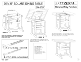
3. One of the two supplied fuse holders will serve
as an isolated stud block. Install the isolated stud
block to the accessory enclosure as shown using
two #10 x 1/2" machine screws and #10 locknuts.
4. The hopper‑side accessory cable assembly will
be routed into the accessory enclosure through
the farthest right break‑through plug. Cut a hole
through the plug to ensure a tight t around the
cable. Run the accessory cable through the
break‑through plug and into the enclosure.
Clamp
Loop
1/4" Locknut
1/4" x 3/4"
Cap Screw
Break-Through Plug
(Cable assembly not shown.)
Install Hopper-Side Accessory Cable
Assembly
1. Detach the accessory enclosure cover from the
enclosure base. Set aside the cover and fasteners.
2. Install the accessory enclosure body to the
hydraulic power group base, at the rear (chute
side) of the feed gate, using three 1/4" x 3/4" cap
screws and 1/4" locknuts.
Feed Gate
Accessory
Enclosure
1/4" Locknut
1/4" x 3/4" Cap Screw
Isolated
Stud Block
#10 Locknut
#10 x 1/2" Machine Screw

99627
Lit. No. 98984, Rev. 00 3 June 15, 2016
5. Remove the cover of the isolated stud block.
Connect the ring terminal on the accessory
cable's red wire to the left stud and the ring
terminal on the black wire to the right stud.
6. Secure the hopper‑side accessory cable assembly
to the passenger side of the accessory enclosure
using the supplied clamp loop, 1/4" x 3/4" cap
screw, and 1/4" locknut.
7. Once the desired spreader accessories have been
installed, replace the cover on the isolated stud
block and reinstall the accessory enclosure cover
using the retained fasteners.
Install Vehicle-Side Accessory Cable
Assembly
1. Before beginning this installation, disconnect the
battery cables from the vehicle battery.
2. Position the supplied fuse holder near the vehicle
battery so the 22" red battery cable can reach
both the POSITIVE (+) battery terminal and
the fuse holder. Install the fuse holder using
1/4" x 3/4" cap screws, 14" at washers, and
1/4" locknuts. Hand tighten the nuts.
NOTE: An accessory 50" or 90" battery cable may
be installed in place of the standard 22" cable for
applications requiring a longer cable.
3. Remove the fuse holder cover. Remove the lock
washers and nuts from both studs. Insert the
supplied 60‑amp fuse. Connect one end of the
battery cable to one of the fuse holder studs so
that the ring terminal is on top of the fuse.
4. Lay out a path for routing the vehicle‑side
accessory cable from the rear of the truck bed to
the vehicle battery, making sure avoid any hot,
sharp, or moving parts of the truck. Routing may
vary from truck to truck.
5. Route the vehicle‑side accessory cable as laid
out in Step 4. Secure the vehicle accessory cable
assembly to the truck using cable ties. Verify that
the cable assembly cannot drop onto the road
when it is disconnected from the spreader.
6. Connect the red wire from the vehicle‑side
accessory cable to the second fuse holder stud so
that the ring terminal is on top of the fuse. Replace
the lock washers and nuts on both studs.
7. Tighten the fuse holder nuts to 106–159 in‑lb.
Snap the fuse holder cover back in place.
8. Connect the other end of the 22" battery cable to
the POSITIVE (+) battery terminal. Connect the
black wire from the vehicle‑side accessory cable
to the NEGATIVE (–) battery terminal.
NOTE: When using a 50" or 90" battery cable,
connect the black wire from the vehicle-side
accessory cable to a ground bolt on the vehicle
frame or engine. Clean off any paint or dirt to
ensure a good connection.
9. Reconnect the vehicle battery cables.

99627
Lit. No. 98984, Rev. 00 4 June 15, 2016
Install Accessory Switch Harness
When installing the accessory switch dash bracket,
choose a location that is within easy reach of the
vehicle operator without restricting access to vehicle
controls or vehicle instrumentation. Do not mount the
control in areas prohibited by the vehicle manufacturer
for crashworthiness. See the vehicle's body builder's
book, owner's manual or service manual for details.
The shaded areas in the illustration below show the
most commonly restricted areas.
NOTE: Use dielectric grease on all electrical
connections.
1. Lay out a path for routing the accessory switch
harness from its connection with the vehicle
accessory cable assembly into the cab of the
truck. Make sure the path avoids any hot, sharp,
or moving parts of the truck. Routing may vary
from truck to truck.
2. Identify a convenient location for the accessory
switch bracket that can be reached by the
accessory switch harness. The bracket has two
sets of mounting holes so it can be installed on
either a horizontal or a vertical surface.
CAUTION
Do not alter, modify or install additional
components in shaded areas shown below.
Failure to comply may interfere with airbag
deployment or cause injury to operator in an
accident.
3. Drill a 5/8" hole in the re wall so the accessory
switch harness can reach to the desired switch
bracket location.
4. Insert the supplied rubber grommet into the hole.
5. Route the accessory switch harness as laid out in
Step 1.
6. Secure the accessory switch harness to the truck
using cable ties
7. Plug the accessory switch harness's connector
into the mating connector on the vehicle‑side
accessory cable assembly. (Refer to the
Vehicle‑Side Harness Diagram.)
CAUTION
Before drilling any holes, check both sides
of the material for any wires, fuel lines, fuel
tanks, etc. that may be damaged by drilling.

99627
Lit. No. 98984, Rev. 00 5 June 15, 2016
5. Strip 1/4" of insulation from the white, orange,
blue, and gray non‑terminated accessory switch
harness wires and crimp a female push‑on
terminal onto each prepared wire. (Refer to the
Vehicle‑Side Harness Diagram.)
6. Connect the colored wires to the rocker switch
terminals as follows:
WHITE strobe lights
ORANGE pre‑wet system
BLUE vibrator
GR AY work light
GREEN (extra switch)
7. Strip 1/4" of insulation from the black wire in the
accessory switch harness and crimp it onto the
insulated butt splice connecter of the 4‑position
jumper assembly. Connect the push‑on terminals
of the 4‑position jumper to the remaining terminals
of the rocker switches.
Install Switch Bracket and Switches
1. Position the switch bracket at the previously
selected location in the vehicle cab.
2. Using the switch bracket as a template, drill three
7/32" holes that align with the mounting holes in
the top or rear face of the bracket.
3. Install the switch bracket using three
#10 x 3/8" tapping screws, #10 lock washers
and #10 hex nuts.
4. Install the 4 rocker switches into the switch bracket
with the red surface facing up. Gently push the
switches into the rectangular holes until they snap
into place.
CAUTION
Before drilling any holes, check both sides
of the material for any wires, fuel lines, fuel
tanks, etc. that may be damaged by drilling.
Red surface
facing up.
Rocker Switch
#10 x 3/8
Tapping Screw
#10 Lock
Washer
#10 Hex Nut

99627
Lit. No. 98984, Rev. 00 6 June 15, 2016
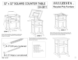
HOPPER-SIDE HARNESS DIAGRAM
BLK
RED
YEL
AB
Isolated Stud Block
(shown with cover removed)
AB
Work/Strobe Lights
Accessorv Relay/Fuse
Assemblies
(Not included in 99627 kit.)
BLK
RED
RED
YEL
BLU
BLK
Accessory Cable Assembly – Hopper Side
BLK (–) Common
WHT Strobe
GRY Work Light
BLU Vibrator
GRN Extra
ORN Pre-Wet
Vibrator

99627
Lit. No. 98984, Rev. 00 7 June 15, 2016
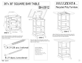
VEHICLE-SIDE HARNESS DIAGRAM
BLK (–) Common
WHT
GRY
BLU
GRN Extra
Strobe
Light
Vibrator Work
Light
Pre-Wet
4-Position Jumper Assembly
ORN
Insulated
Butt Splice
SW1SW2 SW3SW4
1
2
1
2
1
2
1
2
Dealer-Installed
Terminals
Accessory Switch Harness Assembly
Accessory Cable Assembly – Vehicle Side
BLK
RED
BLK
22" RED CABLE
Fuse Holder
w/60A Fuse
NEGPOS
Battery

99627
Lit. No. 98984, Rev. 00 8 June 15, 2016
Copyright © 2016 Douglas Dynamics, LLC. All rights reserved. This material may not be reproduced or copied, in whole or in part, in any
printed, mechanical, electronic, lm or other distribution and storage media, without the written consent of the company. Authorization to
photocopy items for internal or personal use by the company's outlets or spreader owner is granted.
The company reserves the right under its product improvement policy to change construction or design details and furnish equipment when
so altered without reference to illustrations or specications used. This equipment manufacturer or the vehicle manufacturer may require or
recommend optional equipment for spreaders. Do not exceed vehicle ratings with a spreader. The company offers a limited warranty for all
spreaders and accessories. See separately printed page for this important information.
Printed in U.S.A.
/