Page is loading ...

Read And Save These Instructions
MOBILE EVAPORATIVE
COOLER MFC18000
1
Safety Rules
IN ORDER TO REDUCE THE POSSIBILITY OF
FIRES, SHOCK OR PERSONAL INJURY:
1. Unit must be in off position and unplugged from pow-
er receptacle when performing maintenance.
2. To reduce the risk of electrical shock, plug unit into a
properly grounded receptacle.
3. To reduce the risk of electrical shock, install only on a
circuit protected with a ground fault circuit interrupter
(GFCI).
4. This appliance is not intended for use by persons
(including children) with reduced physical, sensory or
mental capabilities, or lack of experience and
knowledge, unless they have been given supervision or
instruction concerning use of appliance by a person
responsible for their safety.
5. Do not operate any cooler with a damaged cord or
plug. Discard the cooler or return to an authorized for
examination and/or repair.
6. Do not run cord under carpeting. Do not cover cord
with throw rugs, runners, or similar coverings. Do not
route cord under furniture or appliances. Arrange cord
away from traffic area and where it will not be tripped
over.
WARNING: To reduce the risk of electrical
fire or shock, do not use this fan with any
“solid-state fan speed control device.”
2
Location
KEY OPERATIONAL POINTS
1. Your cooler must be positioned in front of an open window or door
in order to operate effectively.
2. Always ensure there is another open window or door through
which the air can exhaust from the room.
3. Ensure the media is kept clean throughout the summer season.
4. At the end of each day, run your cooler on FAN ONLY for 30
minutes to dry out the media.
5. Prior to storing your cooler in the off season:
A. Drain the tank and wipe clean
B. Clean the media.
C. Reassemble and run the fan for 30 minutes to dry out the media.
LOCATION! LOCATION! LOCATION!
Having completed the assembly of your cooler, position the unit with
the back side to an open window or door. This will allow fresh air to
be drawn through the cooler and exhausted from the room. Constant
air change is essential and part of the fresh air benefit from evapora-
tive cooling.
Remember, your cooler has been designed to operate even if it runs
out of water. No damage will be caused to the pump if your cooler
runs out of water.
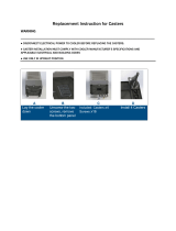
Casters Assembly
Remove the 4 casters and all 16 screws. Using
the screws provided, attach the casters to the
bottom caster plates. Move cooler about to verify
smooth rolling operation.
3
4
Cooler Operation
A. Filling Water
B. Connect to power source: GFCI Protected Only
C. Select Cooling Mode
Cooler Maintenance
Disconnect from power supply
A. Disassemble the back panel
Remove the screws from the back panel. Next,
pull the back panel up.
Pull out the bottom of the back panel, then pull
panel down to remove.
B. Drain the water tank
Remove the drain plug.
Lean the cooler back and
let the water drain out.
Use caution not to let the
cooler fall over.
Drain Plug
Trouble Shooting
NOTICE: This product may temporarily produce
an “odd odor” when first turned on. This is normal
and will dissipate after a few hours.
Option 1: Open water filler door and fill with water
until the “full” graphic appears in the water level
indicator window.
Option 2: Connect garden hose to hose adapter.
This unit is equipped with a float valve and will
seal the water off once the tank is full.
Option 1
Option 2:
Using garden hose
Pump Information:
Pump may need to be primed for 5 to 10 minutes if water isn’t immediately noticed on the media.
To Remove Pump: DISCONNECT COOLER FROM POWER SOURCE
Remove rear panel same as normal maintenance
Remove screws holding pump to inside of housing
Remove distribution hose from pump outlet
Unwire power cord going to pump. Label wires for easier re-installation.
Parts Diagram
No. Part Name Part #
1 water tank
2 rigid media 1800053
3 media panel 1800004
4 right pillar
5 wire holder
6 top cover
7 left pillar
8 motor 1800051
9 float valve 0200058
10 fan blade 1800052
11 motor bracket
12 oscillator motor 1800057
13 venturi
14 oscillator rib
15 grill
16 control box
17 water fill door
18 water level indicator 1800017
19 water pump 1800050
20 caster bracket
21a caster non-locking 1800061
21b caster locking 1800062
drain assembly 0200063
Tech Support:
602.251.2003
/


