Page is loading ...

Millerfi
October
1993
Form:
OM-1586D
Effective
With
Serial
No.
KD497659
OWNERS
MANUAL
Read
and
follow
these
instructions
and
all
safety
blocks
carefully.
Have
only
trained
and
qualified
persons
install,
operate,
or
service
this
unit.
Call
your
distributor
if
you
do
not
understand
the
directions.
SS-64M
(12)
And
(16)
Foot
Boom
Mounted
Wire
Feeder
Microprocessor
Controlled
Constant
Speed
Wire
Feeder
Multi-Power
Source
Compatible
For
GMAW,
GMAW-P,
And
FCAW
Welding
For
.023
To
1/8
in
(0.6
To
3.2
mm)
Wires
Standard
Wire
Feed
Speed
Of
50
To
780
ipm
(1.3
To
19.8
mpm)
Programmable
Pulse
Weld
Parameters
Circuit
Breaker
Protected
Give
this
manual
to
the
operator.
For
help,
call
your
distributor
or:
MILLER
Electric
Mfg.
Co.,
P.O.
Box
1079,
Appleton,
WI
54912
414-734-9821
cover
7/93
ST.157
388
'
1993
MILLER
Electric
Mlg
Co.
PRINTED
IN
USA

MILLERS
TRUE
BLUETM
LIMITED
WARRANTY
Effective
January
1,
1992
(Equipment
with
a
sariai
number
preface
of
KC
or
newer)
This
limited
werrenty
supersedes
eli
previous
MILLER
werrenties
end
is
exclusive
with
no
other
guarantees
or
werrenties
expressed
or
implied.
LIMITED
WARRANTY
Subject
to
the
terms
and
conditions
below,
MILLER
Electric
MI
g.
Co.,
Appleton.
Wisconsin.
warrants
to
its
original
retell
purchaser
that
new
MILLER
aquipmant
sold
after
the
effective
date
of
this
limited
warranty
is
free
of
de
fects
in
material
and
workmanship
at
the
tima
it
is
shipped
by
MtLLER.
TIllS
WAR
RANT?
IS
EXPRESSLY
IN
LIEU
OF
ALL
OTHER
WARRANTIES.
EXPRESS
OR
IMPLIED.
INCLUDING
THE
WARRANTIES
OF
MERCHANTABILITY
AND
FIT
NESS.
Within
the
warranty
periods
listed
below,
MtLLER
will
repair
or
raplaca
any
war
ranted
parts
or
components
that
tail
due
to
such
detects
in
malarial
or
workmanship.
MILLER
must
be
notified
in
writing
within
thirty
(30)
days
of
such
defect
or
tailura,
at
which
time
MILLER
will
provide
instructions
on
the
warranty
claim
procedures
to
ba
followed.
MILLER
shall
honor
warranty
claims
on
warranted
equipment
listed
below
in
the
avant
of
such
a
failure
within
the
warranty
lime
pariods.
All
warranty
time
periods
start
on
the
data
that
the
equipment
was
delivered
to
the
original
retail
purchaser,
or
one
year
after
the
equipment
is
sant
to
the
distributor.
3.
2
Years
Parts
and
Labor
*
Engine
Driven
Welding
Ganarstors
(NOTE:
Engines
era
warranted
separately
by
the
angina
manufacturer.)
Air
Compressors
4.
1
Yasr
Psrts
end
Labor
*
Motor
Driven
Guns
*
Process
Controllers
Water
Coolant
Syatams
*
HF
Units
Grids
*
Spot
Welders
Load
Banks
SDX
Transformers
Running
Gear/Trailers
*
Field
Options
(NOTE:
Field
options
era
covarad
undar
True
Blue
TN
for
the
remaining
warranty
period
ol
tha
producl
Ihey
era
installed
in,
or
for
a
minimum
of
one
year
whichavar
is
graalar.(
6
Months
Batteries
g~
Days
Parts
and
Labor
MIG
Guns/TIG
Torchas
Plasma
Cutting
Torches
U,.
Remote
Controls
*
Accessory
Kits
*
Rapiscamant
Parts
MILLERS
True
BIuaT_
Limited
Warranty
shall
not
apply
to:
1.
Items
furnished
by
MILLER.
but
manutacturad
by
others,
such
as
engines
or
trade
accessories.
These
items
era
covarad
by
the
manufacturers
warranty,
if
any.
2.
Consumable
componants:
such
as
contact
tips,
cutting
nozzles.
contactors
and
relays
or
parts
that
fail
due
to
normal
wear.
3.
Equipment
that
has
bean
modified
by
any
party
other
than
MILLER,
or
aquip
mant
that
has
bean
improperly
installed,
improperly
oparstad
or
misused
based
upon
industry
stsndsrds,
or
equipment
which
has
not
had
reasonable
end
nacasssry
mairttansnca,
or
aquipmant
which
has
baan
used
tor
oparstion
outside
of
the
specifications
for
the
equipment.
MILLER
PRODUCTS
ARE
IHTEHDED
FOR
PURCHASE
AND
USE
BY
COMMER
CIALIINDUSTRIAL
USERS
AND
PERSONS
TRAINED
AND
EXPERIENCED
IN
THE
USE
AND
MAIHTENANCE
OF
WELDING
EQUIPMENT
In
the
avant
of
a
wsrrsnty
claim
covered
by
this
warranty,
the
exclusive
remedies
shall
be.
at
MILLERS
option:
)t)
repair:
or
(2)
rapiacamant;
or.
where
authorized
in
writing
by
MILLER
in
appropriate
cases,
13)
the
reasonable
cost
of
repair
or
replace-
mantel
an
authorizad
MILLER
sarvica
station:
or
(4)
payment
of
or
credit
for
tha
pur
chase
price
(lass
reasonable
dapracistion
based
upon
actual
use)
upon
return
ot
the
goods
at
customers
risk
and
aspansa.
MILLERS
option
of
repair
or
replacement
will
be
FOB..
Factory
atApplaton.
Wisconsin,
or
F.O.B.
ala
MILLER
authorized
ser
vice
facility
as
determined
by
MILLER.
Therefore
no
compansstion
or
reimburse
ment
for
transportation
costs
of
any
kind
will
be
allowed.
TO
THE
EXTENT
PERMITTED
BY
LAW,
THE
REMEDIES
PROVIDED
HEREIN
ARE THE
SOLE
AND
EXCLUSIVE
REMEDIES.
IN
NO
EVENT
SHALL
MILLER
BE
LIABLE
FOR
DIRECT,
INDIRECt
SPECIAL,
INCIDENTAL
OR
CONSEQUENTIAL
DAMAGES
(INCLUDING
LOSS
OF
PROFIT),
WHETHER
BASED
ON
CDN
TRACt
TORT
OR
ANY
OTHER
LEGAL
THEORY.
ANY
EXPRESS
WARRANTY
NOT
PROVIDED
HEREIN
AND
ANY
IMPLIED
WAR
RANTY,
GUARANTY
DR
REPRESENTATION
AS TO
PERFDRMANCE,
AND
ANY
REMEDY
FOR
BREACH
OF
CONTRACT
TORT
DR
ANY
OTHER
LEGAL
THEORY
WHICH,
BUT
FOR
THIS
PROVISION.
MIGHT
ARISE
BY
IMPLICATION.
OPERATIDN
DF
LAW,
CUSTOM
DF
TRADE
DR
COURSE
OF
DEALING,
IN
CLUDING
ANY
IMPLIED
WARRANTY
OF
MERCHANTABILITY
OR
FITNESS
FOR
PARTICULAR
PURPOSE.
WITH
RESPECT
TO
ANY
AND
ALL
EQUIPMENT
FURNISHED
BY
MILLER
IS
EXCLUDED
AND
DISCLAIMED
BY
MILLER.
Some
slates
in
Iha
U.S.A.
do
not
allow
limitations
of
how
long
an
implied
warrsnty
lasts,
or
tha
asclusion
of
incidantal,
indiract,
special
or
consequential
damsgas.
so
Iha
above
iimitstion
or
asciusion
may
not
apply
to
you.
This
warranty
provides
spe
cific
lagal
rights,
and
other
rights
may
ba
available,
but
may
vary
from
stats
to
stats.
In
Csnsds,
Iagislslion
in
soma
provincas
provides
for
certain
additional
warranties
or
remedies
other
than
as
slslad
herein.
and
to
the
aslanl
thaI
they
may
not
be
waived,
the
limitations
and
exclusions
sat
out
above
may
nol
apply.
This
Limited
Warranty
provides
specific
legal
rights,
and
other
rights
may
be
available,
but
may
vary
hom
province
to
province.
1.
5
Yaars
Parts
3
Years
Labor
*
Original
main
power
rectifiers
2.
3
Years
Parts
and
Labor
Transformar/Ractifiar
Powar
Sources
Plasma
Arc
Cutting
Power
Sources
Semi-Automatic
and
Automatic
Wira
Feeders
Robots
5.
B.
I
RECEIVING-HANDLING
Before
unpacking
equipment,
check
carton
for
any
dama9e
that
may
have
occurred
during
Shipment.
File
any
claims
for
loss
or
damage
with
the
deiivering
carrier.
Assistance
for
filing
or
settling
claims
may
be
obtained
from
distributor
and/or
equipment
manufacturers
Transportation
Department.
When
requesting
information
about
this
equipment,
always
provide
Model
Designation
and
Serial
or
Style
Number.
Use
the
following
spaces
to
record
Model
Designation
and
Serial
or
Style
Number
of
your
unit.
The
information
is
located
on
the
rating
label
or
nameplate.
Model
_________
Serial
or
Style
No,
Date
of
Purchase
miller
5/93s

ERRATA
SHEET
June
2,
1994
FORM:
OM-1586D
Use
above
FORM
number
when
ordering
extra
manuals.
CHANGES
TO
SECTION
3
INSTALLATION
Replace
Section
3-11B.
Welding
Wire
Installation:
Installation
Of
Optional
Wire
Reel
And
Reel
Type
Wire
Figure
3-14.
Installation
Of
Optional
Wire
Reel
And
Reel
Type
Wire
CHANGES
TO
SECTION
15
ELECTRICAL
DIAGRAMS
Replace
Figure
15-1.
Circuit
Diagram
For
Wire
Feeder
(see
Pages
2
and
3
on
this
Errata
Sheet)
Replace
Figure
15-2.
Wiring
Diagram
For
Wire
Feeder
Effective
With
Serial
No.
KD497659
And
Following
(see
Pages
4
and
5
on
this
Errata
Sheet)
After
this
manual
was
printed,
refinements
in
equipment
design
occurred.
This
sheet
lists
exceptions
to
data
appearing
later
in
this
manual.
8
5
4
2
.1
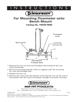
1
Retaining
Ring
2
Spanner
Nut
3
Lock
4
Wire
Retainer
5
Wire
Reel
6
Hub
7
Hub
Pin
8
Reel
Support
Remove
retaining
ring.
Pull
lock
and
turn.
Remove
spanner
nut,
wire
retainer,
and
wire
reel
from
hub.
Lay
wire
reel
assembly
on
flat
sur
face,
and
install
wire
as
shown.
Tighten
spanner
nut
until
lock
is
in
position
over
hole
in
wire
retainer.
Pull
lock
and
turn
to
insert
locking
pin
into
wire
retainer.
Slide
wire
reel
assembly
onto
hub,
and
turn
assembly
until
hub
pin
is
seated
in
hole
in
reel.
Reinstall
re
taining
ring.
ST143
478~A
/
ST-152
463
O
~1T
III~
Wire
Installation

r
USED
WITh
SWIICARC
I
PU
SETAOBPJT
I
PUTIOI
PI.057/PLOS8
I
2<
IC
~
IPV
~
a
a
Figure
15-1.
Circuit
Diagram
For
Wire
Feeder
r
I
CCnCTIPU
FCR
PEICTE
PP~AN
SELECT
I
(SEE
FIELD
INSTPLCTICII
0
C
P
A~a4
I I
I
I
I
I
I
I
I
IOOTO
6
6
6
6 6
I
2
3
PC
100-I>)
PC
100
PC
100-2))
PPS-P
FILTER
BOARD
PcIflfl-fl~
PC
100/PLO
(00
PCI
01
/PLOI
01
N
N
-I
!!~
~
2
0
IPtRDefl
PUI~PQCIT
P060
PC6O/PLO6O
PC6I/DATA
CARD
PC
100-6>)-
00000000
i~r~
Qfl~
,
TI
PUDGIAC
PU
~ISETAo4e0
PUT.
4>--+I
~I
3>).I
.iI
I)-_____))
PLO2P
PLO23
L
:10
PCI
PC
I
0
MIca
twuasIs.M
BOARD
PC
10/PLO
ID
PCI
I/PLO
II
PCI
2/PLO
12
PC
IS/PLO
IS
PCI
6/PLO
16
PCI
7/PLO
I?
PCI
I-4))~-
PCI
I-P)*~
PCI
I
-
I
PCI
I-B>>
PCI
I-6>)~-
PCI
1-3>)
PCI
I-7>)~-
GS
I
I
5CI5~E1<5E-~-*P
L
.1
OM-1
5860
Page
2

RceO~HF
STUD
.lOV
P1M
I
cl~.w~
8LUI
P.S.
c3104
~
)
E
PLO
9
2>
~
>8~W
I>~
P.S.
~TACT~
~,,
I
OM-1586D
Page
3
I
RPS-8
(OPTION)
I
I
ROVTE
PEICANT
PCiuo
PPS-B
SWITDl
BOARD
-I
I
I
I
I
I
PCI
lO/PIGI
10
I
I
I
I
I
I
I
I
I
I
1~lIEI~D
.cPv
-~RCIl0-&
~
(<RCIIO-3
~
(<RCIIO-l
~
III
MT
i
Ii~
ac,v
Ii
I
I
I
8LA
!~((RClI0~2
I
L
-~
I
/0
.50
_____Eco
/0
<<RcGS-4
I~D
~0
~
~
.5y
5
~~v
.IPV
~
-
~
17
PIN
C~S~1
~IPINccP4TP1~LCA&E1
RC8I-F)l7PINc~4a1
Ir>~
)F
PC8I-C
>
cC/CV
(.24V.CV)
Ic>
~
)
C
RC8I-E
>
~.RPD4T
FEE~AO(
(IV/IOOAII
E
>
>
E
RCAI-G>
IPOCTAI~
(0-IOV)
I
G
>
>
0
cOW&CT
RC8I-H
>
VELTAGE
FEE~AOC
IIV/IOVI
1W
>
)
H
T
-
PC5O
INTERFACE
BOARD
RcoO,PL000
R~5
I
/91001
Rco2/P1052
Rc53/PLGG3
Rco4/PIGB4
Pco5iP1Goo
0.04~0
-
pcoA-I
Rc04-7
>>~L.
-.~
cC/Cv
l*24V.cV~<<~~824
D.~4T
F~AD(
I~I~<
RCB2-9
IIO~TAM~
(010V1<<
PCO2-
I
VU.TA~
FEE~(
Ilv/Iovkco~
CIRPENT
S~<~(
RCS2-3
cU1PENT
SE~<<
582-0
R~54-
10
>>~
PcG4-9>)--~--
5c54-6
>>-~L__
Rc04-O
>>-~--~-
502-2
>>-~-
SEISE
SEIIOE
~-(<
RC82-8
~-<<
RCO2-6
PcO3-3>)4~---
IA
PIN
COOl
:pce~-ii
c.
0
C
0
N
c.
I?
VMMVV.~VVVV
~
~
~
PJM
O~1V
PC8O
FILTER
BOARD
RC82/P1082
589/916Th
I,
Il1~
0
TRIGGER
~
A,\,~AA
AAA
C.
.,
C
0
J<RC4-I
M
___________________
PC
I
OTOR
BOARD
55-10)
PC
I
/PLG
I
7
RC3/PLG3
RC2/PLG2
RCA/PLG4
PCG/Pt.65
2
(<RCA-A
RC6/PLG6
<<RC3-4
<<RC3-2
~0I
91070
C1~RO~
SE~
-i
II
II
sce8)-1~-<
(
(~TIOAALl
I
L
L~
FELD
INSTRtETI~G)J
rL~D~I~
SWIIGAPC
____
9
~
~
GPTI~4
C N
C~
Rc84>)~
)B
-<
8<
)e>L~.~cJ~IvE
ASSY
PICK-LP
583:
L
-J
PEI~
589-I
X
RCP9-2
>
589-3
>
r
~
2AVACICT
~KI
)A
CI}iECT
TO
POWER
24VAC
ca.D
~AR
>
~
L
.1
SD-164
705-B
56-I:
/0
I
56-4
p

Figure
15-2.
Wiring
Diagram
For
Wire
Feeder
Effective
With
Serial
No.
KD497659
And
Following
OM-1586D
Page
4

4
I~
__
-
RCIO/PtGIO
]
p
~
r~i~i
I.tP%~G605)It~h
(
(
tt1~t~ir
I
~z~7-~3A(P1G55-I)
j
2;
WII/a
I-I
C~)
0
X3C)
0-
00
P1
U)
U)
0
RC8~ RC83
IDIGIRRC89
p~o~
~PLGTh
~
0
0
0
0
-a
U
_Z~
2~
~322
(-I
z
-~
>0
C)
rn
io,-rr,,3AIPL.GII-I)
38(P1G5~-5)
~l~GII-4)
(0%
1i~~~-el
1
4/C
RIB8~4
J
C,
LrJ
LI
j9
I
I
LIC)
LI
(I
lOG
I
PC8O-
-
RC85I
(4
-
(4~
(I)
(4(4
00
l1
,~
>>
;~9;~
x,-.l
-D
0>
00
l-~.
U)0
1,
I
>
~
63A(PtG6O-3)
,2A(PLG6O-2)
61A(P1G60-lI
2~
I
RC4I/PLG4I
I
II
1/\
I
~
~!
I~
~
OLt~
-~
0~
0
-D
~L~1t~
11
111
IOG(PC4O-RC42)
IQIqP~O-R96)
1W
C,~I-I~EG
44D(RC7-8)
~ca~
~)ci
RC87
=
RC84
9
4
(C
0
(4 LI
3
9
U 0
C,
j9
(4 Ca
0
I,
0
(4
BROWNIPLG9-H)
E~
~
I
YELLOW(PIG9-F)
B~II
2
J
0
(p
0)
0
-u
Ia
(p
CD
9
I~XITI
~JJ~
1~0~n
PIIlC(PLG9-C)
29
(4
0
3OAISI)
0
r
0
IC(SR
I
-
I~IJ
1~0
~
___________
C.
-~0
I~
6LA~I~G9-A)
H
~
I

CHANGES
TO
SECTION
16-
PARTS
LIST
Change
Parts
List
as
follows:
**First
digit
represents
page
no
digits
following
dash
represent
item
no.
+When
ordering
a
component
originally
displaying
a
precautionary
label,
the
label
should
also
be
ordered.
BE
SURE
TO
PROVIDE
MODEL
AND
SERIAL
NUMBER
WHEN
ORDERING
REPLACEMENT
PARTS.
**
Dia.
Mkgs.
Part
No.
Replaced
With
Description
Quantity
.
79-7
124
905
...
+168
104
..
RETAINER,
spool
support
(Eft
wIKE621826)
(consisting
of)
1
166
594
.
.
..
LABEL,
caution
falling
wire
reel
can
cause
damage
1
.
79-8
124904
168
103
..
NUT,
spanner
retaining
(Effw/KE621826)
1
.
81-2
164
842
164
842
..
METER,
(qty
chg)
(used
on
front
meter
only)
1
.
81-2
164842
155
024
..
LENS,
clear
anti
glare
(used
on
side
meter
only)
...
1
.
81-10
.
. .
.
PC1O
....
164713
161
781
..
CIRCUITCARD,processorw/prom
1
.
82-34
...
PLG1O3
...
135
635
Deleted
..
Eff
w/KE593886
.
82-43
154
932
167
698
..
PANEL,
front
(Eff
w/KE623992)
1
.
82-44
157
113
010291
..
WASHER,
flat
.625
ID
nylafil
(Effw/KE623992)
....
1
.
82-45
097
924
167700
..
KNOB,
pointer
(Eff
w/KE623992)
1
. .
82-
Added
..
.
.
167
633
..
WASHER,
shldr
.612
ID
(Eff
w/KE623992)
1
.
.
82-
Added
. .
.
.
159
264
..
RING,
rtng
ext
.625
shaft
grv
x
.045
thk
E
style
(Eff
w/KE623992)
1
.
.
83-15
83-20
133
603
...
154031
.
165
934
..
167
387
..
SPRING,
cprsn
.573
OD
x
.088
wire
x
1.062
lg
(Eff
w/KE644333)
SPACER,
locating
(Eff
w/KE552693)
2
2
.
.
83-
Added
165
799
..
WASHER,
flat
.257
ID
stl
(Eff
w/KE644333)
2
. .
83-
Added
165
798
..
SPRING,
pressure
arm
retaining
(Eff
w/KE644333)
.
2
. .
83-
Added
163
282
..
NUT,
.250-28
stl
(Eff
w/KE644333)
2
.
85-1
057
357
010 493
..
BUSHING,
snap-in
nyl
.625
ID
x
.875mtg
hole
1
OM-1
586D
Page
6

ARC
WELDING
SAFETY
PRECAUTIONS
ELECTRIC
SHOCK
can
kill.
Touching
live
electrical
parts
can
cause
fatal
shocks
or
severe
burns.
The
electrode
and
work
Circuit
IS
electrically
live
whenever
the
output
is
on.
The
input
power
circuit
and
machine
internal
circuits
are
also
live
when
power
is
on.
In
semiautomatic
or
automatic
wire
welding,
the
wire,
wire
reel,
drive
roll
housing,
and
all
metal
parts
touching
the
welding
wire
are
electrically
live.
Incorrectly
installed
or
improperly
grounded
equipment
is
a
hazard.
1.
Do
not
touch
live
electrical
parts.
2.
Wear
dry.
hole-free
insulating
gloves
and
body
protection.
3.
Insulate
yourself
from
work
and
ground
using
dry
insulating
mats
or
covers.
4.
Disconnect
input
power
or
stop
engine
before
installing
or
servicing
this
equipment.
WELDING
can
cause
fire
or
explosion.
Sparks
and
spatter
fly
off
from
the
welding
arc.
The
flying
sparks
and
hot
metal,
weld
spatter,
hot
workpiece,
and
hot
equipment
can
cause
fires
and
burns.
Accidental
contact
of
electrode
orwelding
wire
to
metal
objects
can
cause
sparks,
overheating,
or
fire.
Protect
yourself
and
others
from
flying
sparks
and
hot
metal.
Do
not
weld
where
flying
sparks
can
strike
flammable
material.
Remove
all
flammables
within
35
ft
(10.7
m)
of
the
welding
arc.
If
this
is
not
possible,
tightly
cover
them
with
approved
covers.
Be
alert
that
welding
sparks
and
hot
materials
from
welding
can
through
small
cracks
and
openings
to
adjacent
areas
FLYING
SPARKS
AND
HOT
METAL
can
cause
injury.
Chipping
and
grinding
cause
flying
metal.
As
welds
cool,
they
can
throw
off
slag.
ARC
WELDING
can
be
hazardous.
5.
Properly
install
and
ground
this
equipment
according
to
its
Owners
Manual
and
national,
state,
and
local
codes.
6.
When
making
input
connections,
attach
proper
grounding
conductor
first.
7.
Turn
off
all
equipment
when
not
in
use.
8.
Do
not
use
worn,
damaged,
undersized,
or
poorly
spliced
cables.
9.
Do
not
wrap
cables
around
your
body.
10.
Ground
the
workpiece
to
a
good
electrical
(earth)
ground.
11.
Do
not
touch
electrode
if
in
contact
with
the
work
or
ground.
12.
Use
only
well-maintained
equipment.
Repair
or
replace
damaged
parts
at
once.
13.
Wear
a
safety
harness
if
working
above
floor
level.
14.
Keep
all
panels
and
covers
securely
in
place.
5.
Watch
for
fire,
and
keep
a
fire
extinguisher
nearby.
6.
Be
aware
that
welding
on
a
ceiling,
floor,
bulkhead,
or
partition
can
cause
fire
on
the
hidden
side.
7.
Do
not
weld
on
closed
containers
such
as
tanks
or
drums.
8.
Connect
work
cable
to
the
work
as
close
to
the
welding
area
as
practical
to
prevent
welding
current
from
traveling
long,
possibly
unknown
paths
and
causing
electric
shock
and
fire
hazards.
Do
not
use
welder
to
thaw
frozen
pipes.
Remove
stick
electrode
from
holder
or
cut
off
welding
wire
at
contact
tip
when
not
in
use.
11.
Wear
oil-free
protective
garments
such
as
leather
gloves,
heavy
shirt,
cuffless
trousers,
high
shoes,
and
a
cap.
1.
Wear
approved
face
shield
or
safety
goggles.
Side
shields
recommended.
2.
Wear
proper
body
protection
to
protect
skin.
a
WARNING
PROTECT
YOURSELF
AND
OTHERS
FROM
POSSIBLE
SERIOUS
INJURY
OR
DEATH.
KEEP
CHILDREN
AWAY.
PACEMAKER
WEARERS
KEEP
AWAY
UNTIL
CONSULTING
YOUR
DOCTOR.
In
welding,
as
in
most
jobs,
exposure
to
certain
hazards
occurs.
Welding
is
safe
when
precautions
are
taken.
The
safety
information
given
below
is
only
a
summary
of
the
more
complete
safety
information
that
will
be
found
in
the
Safety
Standards
listed
on
the
next
page.
Read
and
follow
all
Safety
Standards.
HAVE
ALL
INSTALLATION,
OPERATION,
MAINTENANCE,
AND
REPAIR
WORK
PERFORMED
ONLY
BY
QUALIFIED
PEOPLE.
ARC
RAYS
can
burn
eyes
and
skin;
ARC
RAYS
~
NOISE
can
damage
hearing.
2.
Wear
a
welding
helmet
fitted
with
a
proper
shade
of
filter
(see
ANSI
Z49.
I
listed
in
Safety
Standards)
to
protect
your
face
and
Arc
rays
from
the
welding
process
produce
intense
eyes
when
welding
or
watching.
heat
and
strong
ultraviolet
rays
that
can
burn
eyes
3.
Wear
approved
safety
glasses.
Side
shields
recommended.
and
skin.
Noise
from
some
processes
can
damage
hearing.
~
Use
protective
screens
or
barriers
to
protect
others
from
flash
and
glare;
warn
others
not
to
watch
the
arc.
NOISE
5.
Wear
protective
clothing
made
from
durable,
flame-resiŒtant
1.
Use
approved
ear
plugs
or
ear
muffs
if
noise
level
is
high.
material
(wool
and
leather)
and
foot
protection.
FUMES
AND
GASES
can
be
hazardous
5.
Work
in
a
confined
space
only
if
it
is
well
ventilated,
or
while
~~:
.~
to
your
health.
wearing
an
air-supplied
respirator.
Shielding
gases
used
for
~
Weldingproducesfumesandgases.
Breathingthese
welding
can
displace
air
causing
injury
or
death.
Be
sure
the
fumes
and
gases
can
be
hazardous
to
your
health.
breathing
air
is
safe.
6.
Do
not
weld
in
locations
near
degreasing,
cleaning,
or
spraying
operations.
The
heat
and
rays
of
the
arc
can
react
with
vapors
to
1.
Keep
your
head
out
of
the
fumes.
Do
not
breathe
the
fumes.
form
highly
toxic
and
irritating
gases.
2.
If
inside,
ventilate
the
area
and/or
use
exhaust
at
the
arc
to
remove
welding
fumes
and
gases.
7.
Do
not
weld
on
coated
metals,
such
,as
galvanized,
lead,
or
3.
If
ventilation
is
poor,
use
an
approved
air-supplied
respirator.
cadmium
plated
steel,
unless
the
coating
is
removed
from
the
4.
Read
the
Material
Safety
Data
Sheets
(MSDS5)
and
the
weld
area,
the
area
is
well
ventilated,
and
if
necessary,
while
manufacturers
instruction
for
metals,
consumables,
coatings,
wearing
an
air-supplied
respirator.
The
coatings
and
any
metals
and
cleaners,
containing
these
elements
can
give
off
toxic
fumes
if
welded.
1.
2.
3.
4.
9.
10.
srI
9/92

CYLINDERS
can
explode
if
damaged.
Shielding
gas
cylinders
contain
gas
under
high
pressure.
If
damaged,
a
cylinder
can
explode.
Since
gas
cylinders
are
normally
part
of
the
welding
process,
be
sure
to
treat
them
carefully.
1.
Protect
compressed
gas
cylinders
from
excessive
heat,
mechanical
shocks,
and
arcs.
2.
Install
and
secure
cylinders
in
an
upright
position
by
chaining
them
to
a
stationary
support
or
equipment
cylinder
rack
to
prevent
falling
or
tipping.
a
WARNING
3.
Keep
cylinders
away
from
any
welding
or
other
electrical
circuits.
4.
Never
allow
a
welding
electrode
to
touch
any
cylinder.
5.
Use
only
correct
shielding
gas
cylinders,
regulators,
hoses,
and
fittings
designed
for
the
specific
application;
maintain
them
and
associated
parts
in
good
condition.
6.
Turn
face
away
from
valve
outlet
when
opening
cylinder
valve.
7.
Keep
protective
cap
in
place
over
valve
except
when
cylinder
is
in
use
or
connected
for
use.
8.
Read
and
follow
instructions
on
compressed
gas
cylinders,
associated
equipment,
and
CGA
publication
P-i
listed
in
Safety
Standards.
PRINCIPAL
SAFETY
STANDARDS
Safety
in
Welding
and
Cutting,
ANSI
Standard
Z49.i,
from
American
Welding
Society,
550
N.W.
Le.Jeune
Rd,
Miami
FL
33126
Safetyand
Health
Standards,
OSHA29
CFR
1910,
from
Superinten
dent
of
Documents,
U.S.
Government
Printing
Office,
Washington,
D.C.
20402.
Recommended
Safe
Practices
for
the
Preparation
for
Welding
and
Cutting
of
Containers
That
Have
Held
Hazardous
Substances,
Ameri
can
Welding
Society
Standard
AWS
F4.1,from
American
Welding
So
ciety,
550
N.W.
LeJeune
Rd,
Miami,
FL
33126
National
Electrical
Code,
NFPA
Standard
70,
from
National
Fire
Pro
tection
Association,
Batterymarch
Park.
Quincy,
MA
02269.
Safe
Handling
of
Compressed
Gases
in
Cylinders,
CGA
Pamphlet
P-i,
from
Compressed
Gas
Association,
1235
Jefferson
Davis
High
way,
Suite
501,
Arlington,
VA
22202.
Code
for
Safety
in
Welding
and
Cutting,
CSA
Standard
Wi
17.2,
from
Canadian
Standards
Association,
Standards
Sales,
178
Rexdale
Bou
levard,
Rexdale,
Ontario,
Canada
M9W
1
R3.
Safe
Practices
For
Occupation
And
Educational
EyeAnd
Face
Protec
tion,
ANSI
Standard
Z87.i,
from
American
National
Standards
Institute,
1430
Broadway,
New
York,
NY
10018.
Cutting
And
Welding
Processes,
NFPA
Standard
51
B.
from
National
Fire
Protection
Association,
Batterymarch
Park,
Quincy,
MA
02269.
ENGINE
EXHAUST
GASES
can
kill.
1.
Use
equipment
outside
in
open,
well-ventilated
areas.
ENGINES
can
be
hazardous.
2.
If
used
in
a
closed
area,
vent
engine
exhaust
outside
and
Engines
produce
harmful
exhaust
gases.
away
fr
om
any
building
air
intakes.
ENGINE
FUEL
can
cause
fire
or
1.
Stop
engine
before
checking
or
adding
fuel.
4
explosion.
Engine
fuel
is
highly
flammable.
2.
3.
4.
5.
Do
not
add
fuel
while
smoking
or
if
unit
is
near
any
sparks
or
open
flames.
Allow
engine
to
cool
before
fueling.
If
possible,
check
and add
fuel
to
cold
engine
before
beginning
job.
Do
not
overfill
tank
allow
room
for
fuel
to
expand.
Do
not
spill
fuel.
If
fuel
is
spilled,
clean
up
before
starting
engine.
MOVING
PARTS
can
cause
injury.
Moving
parts,
such
as
fans,
rotors,
and
belts
can
cut
fingers
and hands
and
catch loose
clothing,
3.
4.
Have
only
qualified
people
remove
guards
or
covers
for
maintenance
and
troubleshooting
as
necessary.
To
prevent
accidental
starting
during
servicing,
disconnect
negative
(.)
battery
cable
from
battery.
1.
Keep
all
doors,
panels,
covers,
and
guards
closed
and
securely
in
place.
5.
6.
Keep
hands,
hair,
loose
clothing,
and
toots
away
from
moving
parts.
Reinstall
panels
or
guards
and
close
doors
when
servicing
is
2.
Stop
eng
ne
before
installing
or
connecting
unit,
finished
and
before
starting
engine.
SPARKS
can
cause
BATTE
TO
EXPLODE;
BATTERY
RY
GASES
ACID
can
1.
2.
Always
wear
Stop
engine
a
face
s
before
hietd
when
working
on
a
battery.
disconnecting
or
connecting
battery
burn
eyes
and
skin,
cables.
3.
Batteries
contain
acid
and
generate
explosive
4.
Do
not
allow
tools
to
cause
sparks
when
working
on
a
battery.
Do
not
use
welder
to
charge
batteries
or
jump
start
vehicles.
gases.
5.
Observe
correct
polarity
(+
and
)
on
batteries.
.
.
~-
/
STEAM
AND
COOLANT
can
skin.
The
coolant
in
the
under
pressure.
PRESSURIZED
burn
face,
eyes,
radiator
can
be
very
ho
HOT
and
t
and
i.
2.
3.
Donotremoveradiatorcapwhenengineishot.Allowengine
to
cool.
Wear
gloves
and
put
a
rag
over
cap
area
when
removing
cap.
Allow
pressure
to
escape
before
completely
removing
cap.
Sri
9/92

PRECAUTIONS
DE
SECURITE
EN
SOUDAGE
A
LARC
DESSAI.
LELECTROCUTION
peut
Œtre
mortelle.
Une
dØcharge
Ølectrique
peut
vous
tuer
ou
vous
brler
gravement.
LØlectrode
et
le
circuit
de
soudage
sont
sous
tension
au
demarrage.
Le
circuit
dentrØe
et
les
circuits
internes
des
matØriels
sont
aussi
sous
tension
des
Ia
mise
en
marche.
En
soudage
ou
semi-automatique
avec
til,
ce
dernier,
le
support
de
roquette,
le
logement
des
galets
dentraInement
et
toutes
les
piŁces
metalliques
en
contact
avec
le
fil
de
soudage
sont
sous
tension.
Des
matØriels
mal
installØs
ou
mal
mis
a
a
terre
sont
dangereux.
1.
Ne
touchez
pas
a
des
piŁces
sous
tension.
2.
Portez
des
gants
et
des
vØtements
isolants,
secs
et
non
trouŁs.
3.
lsolez-vous
de
Ia
tle
a
souder
et
de
Ia
mise
ala
terre
au
moyen
de
petits
tapis
isolants
ou
autres.
4.
DØconnectez
Ia
prise
dentrØe
des
matØriels
ou
arrŒtez
leur
moteur
avant
de
les
installer
ou
den
faire
Ientretien.
C~
Le
RAYONNEMENT
DE
LARC
peut
brUler
(es
yeux
et
Ia
peau;
le
BRUIT
peut
endommager
IouIe.
Larc
de
soudage
produit
une
chaleur
et
des
rayons
ultraviolets
intenses,
susceptibles
de
brler
les
yeux
et
a
peau.
Le
bruit
cause
par
certains
procŁdes
peut
endommager
louIe.
1.
Portez
un
casque
de
soudeur
avec
Øcran
filtrant
de
teinte
appropriØe
(consultez
Ia
norme
ANSI
Z49
indiquee
ci-apres),
pour
vous
protØger
le
visage
et
les
yeux
Iorsque
vous
soudez
ou
I
Les
VAPEURS
ET
LES
FUMEES
sont
~
dangereuses
pour
Ia
sante.
U
Le
soudage
degage
des
vapeurs
et
des
fumØes
quil
=9..
est
dangereux
de
respirer.
1.
Ecartez
le
visage
pour
Øviter
de
respirer
les
tumØes.
2.
A
lintØrieur,
assurez-vous
que
laire
de
soudage
est
bien
ventilØe
ou
que
es
fumØes
et
les
vapeurs
sont
aspirees
a
arc.
3.
Si
Ia
ventilation
est
mauvaise,
portez
un
respirateur
a
adduction
dair
approuvØ.
4.
Lisez
les
fiches
signaletiques
et
les
consignes
du
fabricant
relatives
aux
mØtaux,
aux
produits
consummables,
aux
revŒtements
et
aux
produits
nettoyants.
~
~
Le
SOUDAGE
peut
causer
un
incendie
(~
~
ou
une
explosion.
Larc
produit
des
Øtincelles
et
des
projections.
Avec
Ia
chaleur
intense
dØgagee
par
Ia
tle
et
les
matØriels,
elles
peuvent
causer
un
incendie
et
des
brlures.
Le
contact
accidentel
de
lelectrode
avec
un
objet
mØtallique
peut
provoquer
des
Øtincelles,
un
Øchauffement
ou
un
incendie.
1.
Protegez-vous,
ainsi
que
les
autres,
contre
les
Łtincelles
et
les
projections.
2.
Ne
soudez
pas
dans
un
endroit
o
des
Øtincelles
peuvent
atteindre
des
matØriaux
inflammables.
3.
Enlevez
toutes
es
matiŁres
inflammables
dans
un
rayon
de
10,7
metres
autour
de
larc,
ou
couvrez-les
soigneusement
avec
des
bÆches
approuvees.
4.
MØfiez-vous
des
Øtincelles
et
des
Øclats
brUlants,
susceptibles
de
pØnØtrerdans
des
aires
adjacentes
parde
petites
ouvertures
ou
fissures.
LE
SOUDAGE
A
LARC
est
dangereux.
5.
Veillez
a
installer
ces
matØriels
eta
les
mettre
ala
terre
selon
le
manuel
dutilisation
et
les
codes
nationaux,
provinciaux
et
locaux
applicables.
6.
ArrŒtez
tous
es
matØriels
apres
utilisation.
7.
Nutilisez
pas
de
cables
uses,
endommagØs,
mal
ŁpissØs
ou
de
calibre
trop
petits.
8.
Nenroulez
pas
de
cables
autour
de
votre
corps.
9.
Mettez
ala
terre
Ia
tle
a
souder
au
moyen
dune
bonne
prise
de
terre.
10.
Ne
touchez
pas
a
IØlectrode
Si
vous
Øtes
en
contact
avec
le
circuit
de
Soudage
(terre).
11.
Nutilisez
que
des
matØriels
en
bon
Øtat.
RØparez
ou
remplacez
sur-le-champ
les
piŁces
endommagees.
12.
Portez
un
harnais
de
sØcuritØ
si
vous
travaillez
en
hauteur.
13.
Fermez
solidement
tous
les
panneaux
et
les
capots.
que
vous
observez
lexØcution
dune
soudure.
2.
PortezdeslunettesdesØcuritØapprouvØes.
Des
Øcran~
latØraux
sont
recommandees.
3.
Entourez
laire
de
soudage
de
rideaux
ou
de
cloisons
de
protection
contre
les
coups
darc
ou
lØblouissement;
avertissez
les
observateurs
de
ne
pas
regarder
larc.
4.
Portez
des
vŒtements
en
tissus
ignifuge
durable
(lame
et
cuir)
et
des
chaussures
de
sØcuritØ.
5.
Portez
un
casque
antibruit
ou
des
bouchons
doreille
approuvØs
si
le
niveau
de
bruit
est
ØlevØ.
5.
Ne
travaillez
dans
un
espace
confine
que
siI
est
bien
ventilØ;
sinon,
portez
un
respirateura
adduction
dair.
Les
gaz
protecteurs
de
soudage
peuvent
dØplacer
loxygene
de
lair
et
causer
des
blessures
ou
Ia
mort.
Assurez-vous
que
lair
eSt
propre
a
Ia
respiration.
6.
Ne
soudez
pas
a
proximite
dopØrations
de
degraissage,
de
nettoyage
ou
de
pulvØrisation.
La
chaleur
et
les
rayons
de
larc
peuvent
rØagir
avec
des
vapeurs
et
former
des
gaz
hautement
toxiques
et
irritants.
7.
Ne
soudez
pas
de
tles
galvanisØesou
plaquees
en
p10mb
ou
en
cadmium
sans
les
avoir
grattØes
a
fond,
car
ces
mØtaux,
et
tout
revŒtement
qui
en
contient,
peuvent
alors
dØgager
des
fumees
toxiques.
Assurez-vous
dune
bonne
ventilation
et
portez
un
respirateur
a
adduction
dair
si
cest
nØcessaire.
5.
MØfiez-vous
des
incendies
et
gardez
un
extincteur
a
portØe
de
Ia
main.
6.
Noubliez
pas
quune
soudure
sur
un
plafond,
un
plancher,
une
cloison
ou
une
paroi
peut
en
entlammer
Iautre
ctØ.
7.
Ne
soudez
pas
un
recipient
fermØ,
comme
un
reservoir
ou
un
tonneau.
8.
Connectez
le
cable
de
soudage
le
plus
prŁs
possible
de
Ia
tle
de
soudage
pour
empØcher
le
courant
de
suivre
un
parcours
long
et
inconnu,
et
prØvenir
ainsi
les
risques
dØlectrocution
et
dincendie.
9.
Ne
faites
pas
degeler
des
tuyaux
avec
un
chalumeau.
10.
Videz
votre
carquois
porte-electrodes
ou
coupez
le
fil
au
tube-
contact
aprŁs
le
soudage.
11.
Portez
des
vØtements
protecteurs
non
huileux,
tels
des
gants
en
cuir,
une
chemise
Øpaisse,
un
pantalon
sans
revers,
des
chaussures
montantes
et
un
casque.
MISE
EN
GARDE
PROTEGEZ-VOUS,
AINSI
OUE
LES
AUTRES,
CONTRE
LES
BLESSURES
GRAVES
POSSIBLES
OU
LA
MORT.
NE
LAISSEZ
PAS
LES
ENFANTS
SAPPROCHER,
NI
LES
PORTEURS
DE
STIMULATEUR
CARDIAQUE
(A
MOINS
QUILS
NAIENT
CONSULTE
UN
MEDECIN).
Le
soudage,
comme
Ia
plupart
des
activitØs
industrielles,
expose
a
certains
risques.
Le
soudage
nest
pas
dangereux
lorsquon
prend
des
precautions.
Les
consignes
de
sØcuritØ
suivantes
ne
font
que
rØsumer
information
contenue
dans
les
normes
ØnumØrŁes
ci-apres.
Lisez
et
respectez
toutes
ces
normes.
SEULES
DES
PERSONNES
QUALIFIEES
DOIVENT
FAIRE
DES
TRAVAUX
DINSTALLATION,
DE
REPARATION,
DENTRETIEN
ET
d

Les
BOUTEILLES
endommagees
peuvent
exploser.
Les
bouteilles
contiennent
des
gaz
protecteurs
sous
haute
pression.
Des
bouteilles
endommagees
peuvent
exploser.
Comme
les
bouteilles
font
normalement
partie
du
procedØ
de
soudage,
traitez-les
avec
soin.
1.
Les
bouteilles
doivent
Œtre
protOgØes
contre
les
sources
de
chaleur
intense,
les
chocs
et
les
arcs
de
soudage.
2.
EnchaInez
verticalement
les
bouteilles
a
un
support
ou
a
un
cadre
fixe
pour
les
empŒcher
de tomber
ou
dŒtre
renversØes.
3.
Eloignez
les
bouteilles
de
tout
circuit
Ølectrique
ou
de
soudage.
MISE
EN
GARDE
Le
CARBURANT
peut
causer
un
incendie
ou
une
explosion.
Le
carburant
est
hautement
inflammable.
I
~
ArrŒtez
le
moteur
avant
de
verifier
le
niveau
de
carburant
ou
do
faire
le
plein.
2.
Ne
faites
pas
le
plein
en
fumant
ou
proche
dune
source
Des
PIECES
EN
MOUVEMENT
peuvent
causer
des
blessures.
Des
piŁces
en
mouvement,
telles
des
ventilateurs,
des
rotors
et
des
courroies
peuvent
couper
es
doigts
et
les
mains,
ou
accrocher
des
vŒtements
amples.
1.
Assurez-vous
que
es
portes,
los
panneaux,
les
capots
et
los
protecteurs
sont
bien
fermØs.
2.
Avant
dinstaller
ou
do
connecter
un
systeme,
arrŒtez-en
le
moteur.
3.
Seules
des
personnes
qualifiØes
doivent
dØmonter
des
4.
EmpŒchez
tout
contact
entre
une
bouteille
et
une
electrode.
5.
Nutilisez
que
des
bouteilles
de
gaz
protecteur,
des
dØtendeurs,
des
flexibles
et
des
raccords
concus
pour
chaque
application
spØcifique;
ces
matØriels
et
les
piŁces
connexes
doivent
Øtro
en
bon
Łtat.
6.
Ne
mettez
pas
le
visage
devant
le
robinet
de
bouteille
en
louvrant.
7.
Remettez
le
chapeau
de
bouteille
apres
utilisation.
8.
Lisez
et
respectez
les
consignes
relatives
aux
bouteilles
de
gaz
comprimØ
et
aux
matØriels
connexes,
ainsi
que
Ia
publication
P-i
de
Ia
CGA,
ØnumŁrØes
dans
les
normes
ci-dessous.
Les
MOTEURS
peuvent
Œtre
dangereux.
dØtincelles
ou
dune
flamme
flue.
3.
Si
cest
possible,
laissez
le
moteur
refroidir
avant
de
faire
le
plein
do
carburant
ou
den
verifier
le
niveau
au
debut
du
soudage.
4.
Ne
faites
pas
le
plein
do
carburant
a
ras
bord
:
prØvoyez
do
espace
pour
son
expansion.
--
5.
Faites
attention
done
pas
renverser
do
carburant.
Nettoyez
tout
carburant
renversØ
avant
do
faire
dØmarrer
le
moteur.
protecteurs
ou
des
capots
pour
faire
lentretien
ou
le
depannage
nŁcessaire.
4.
Pour
empŒcher
un
dØmarrage
accidentel
dun
systŁme
pendant
lentretien,
dŁbranchez
le
cable
daccumulateur
a
a
borne
negative.
5.
Napprochez
pas
los
mains
ou
los
cheveux
de
piŁces
en
mouvemont;
elles
peuvent
aussi
accrocher
des
vŒtements
amplos
et
des
outils.
6.
RØinstallez
los
capots
ou
los
protecteurs
et
fermez
los
portes
apres
des
travaux
dentretien
of
avant
de
faire
dØmarrer
le
moteur.
Safety
in
Welding
and
Cutting
norme
ANSI
Z49.
1,
American
Welding
Society,
550,
N.W.
LeJeune
Rd.,
Miami
FL
33128.
Safety
and
Health
Standards
OSHA
29
CFR
1910,
Superintendent
of
Documents,
U.S.
Government
Printing
Office,
Washington
D.C.
20402.
Recommended
Safe
Practices
For
the
Preparation
For
Welding
and
Cutting
of
Containers
That
Have
Held
Hazardous
Substances
norme
AWS
F4.1,
American
Welding
Society,
550,
N.W.
LoJoune
Rd.,
Miami
FL
33128.
Safe
Handling
of
Comoressed
Gases
in
Cylinders
document
P-i,
Compressed
Gas
Association,
1235
Jefferson
Davis
Highway,
Suite
501,
Arlington,
Va
22202.
Code
for
Safety
in
Welding
and
Cutting
norme
CSA
Wi
17.2,
Asso
ciation
canadienne
de
normalisation,
Standards
Sales,
176
Rexdale
Boulevard,
Rexdale,
Ontario,
Canada
M9W
1
R3.
Safe
Practices
for
Occupation
and
Educational
Eve
and
Face
Protec
ti~n,
norme
ANSI
Z87.
1
American
National
Standards
Institute,
1430
Broadway,
New
York,
NY
10018.
National
Electrical
Code
norme
70
NFPA,
National
Fire
Protection
Association,
Batterymarch
Park,
Quincy,
MA
02269.
srlt
9/91
Cutting
and
Welding
Processes
norme
51B
NFPA,
National
Fire
Protection
Association,
Batterymarch
Park,
Quincy,
MA
02269.
LES
ETINCELLES
ET
LES
metal.
En
refroidissant,
Ia
soudure
peut
projeter
du
laitier.
PROJECTIONS
BRULANTES
peuvent
causer
des
blessures.
Le
piquage
et
le
meulage
produisent
des
Øclats
de
1.
2.
Portez
un
Øcran
facial
ou
des
lunettes
a
coques
approuvØes.
Des
Øcrans
latØraux
sont
recommandØs.
Portez
des
vŒtements
de
protection
individuelle
appropriØs.
-r
Les
GAZ
DECHAPPEMENT
D
ES
MOTEURS
1.
Utilisez
des
machines
a
lextØrieur
dans
des
aires
ouvertes
et
PEUVENT
ETRE
MORTELS.
bien
ventilØes.
Les
moteurs
produisent
des
gaz
nocits.
dØchappement
2.
Si
vous
utilisez
des
machines dans
un
endroit
confine,
les
fumØes
dechappement
doivent
Œtre
envoyØes
a
lextØrieur,
loin
des
prises
dair
du
btiment.
Des
ETINCELLES
peuvent
FAIRE
EXPLOSER
UNACCUMULATEUR;LELECTROLYTEDUN
ACCUMULATEUR
peut
brUter
Ia
peau
et
es
2.
~
un
accumulateur.
ArrŒtez
le
moteur
avant
de
connecter
ou
de
dØconnecter
des
cables
daccumulateur.
Nutilisoz
quo
des
outils
anti-Łtincollos
pour
travailler
sur
un
yeUX.
accumulateur.
Los
accumulateurs
contiennent
de
lØlectrolyte
et
4.
Nutilisez
pas
un
poste
do
soudage
pou(chargerun
accumulateur
degagent
dos
vapeurs
explosives.
ou
connecter
provisoirement
un
vŁhicule.
1.
Portez
toujours
un
Øcran
facial
en
travaillant
sur
5.
Utilisez
Ia
polarite
correcte
(+
et
-)
de
laccumulateur.
La
VAPEUR
ET
LE
LIQUIDE
DE
1.
Ntezpaslebouchonderadiateurtantquelemoteurnapas
REFROIDISSEMENT
BROLANT
SOUS
refroidi.
PRESSION
peuvent
brUler
Ia
peau
et
es
Øux
-
Le
liquide
do
refroidissement
dun
radiateur
peut
etre
2.
3.
Mettezdesgantsetposezuntorchonsurlebouchonpourloter.
Laissez
Ia
pression
sØchapper
avant
doter
complŁtement
le
bouchon.
.
brlant
et
sous
pression.
PRINCIPALES
NORMES
DE
SECURITE

EMF
INFORMATION
N
OTE
~
Considerations
About
Welding
And
The
Effects
Of
Low
Frequency
Electric
And
_____________________
Magnetic
Fields
The
following
is
a
quotation
from
the
General
Conclusions
Section
To
reduce
magnetic
fields
in
the
workplace,
use
the
following
of
the
U.S.
Congress,
Office
of
Technology
Assessment,
Biological
procedures:
Effects of
Power
Frequency
Electric
&
Magnetic
Fields
1.
Keep
cables
close
together
by
twisting
or
taping
them.
Background
Paper,
OTA-BP-E-53
(Washington,
DC:
U.S.
Government
Printing
Office,
May
1989):
.
. .
there
is
now
a
very
2.
Arrange
cables
to
one
side
and
away
from
the
operator.
large
volume
of
scientific
findings
based
on
experiments
at
the
3.
Do
not
coil
or
drape
cables
around
the
body.
cellular
level
and
from
studies
with
animals
and
people
which
clearly
4.
Keep
welding
power
source
and
cables
as
far
away
as
establish
that
low
frequency
magnetic
fields
can
interact
with,
and
nractical
produce
changes
in,
biological
systems.
While
most
of
this
work
is
of
very
high
quality,
the
results
are
complex.
Current
scientific
5.
Connect
work
clamp
to
workpiece
as
close
to
the
weld
as
understanding
does
not
yet
allow
us
to
interpret
the
evidence
in
a
possible.
single
coherent
framework.
Even
more
frustrating,
it
does
not
yet
About
Pacemakers:
allow
us
to
draw
definite
conclusions
about
questions
of
possible
The
above
procedures
are
among
those
also
normally
risk
or
to
offer
clear
science-based
advice
on
strategies
to
minimize
recommended
for
pacemaker
wearers.
Consult
your
doctor
for
or
avoid
potential
risks.
complete
information.
modlo
I
4/93
TABLE
OF
CONTENTS
SECTION
1
SAFETY
INFORMATION
-
1
SECTION
2
SPECIFICATIONS
1
SECTION
3
INSTALLATION
3-1.
Equipment
Connection
Diagram
2
3-2.
Installing
Swivel
Into
Pipe
Post
3
3-3.
Installing
Boom
And
Reel
Support
3
3-4.
Installing
Wire
Guide
Extension
4
3-5.
Wire
Guide
And
Drive
Roll
Installation
4
3-6.
Welding
Gun
Connections
5
3-7.
Wire
Feed
Motor
And
Gas
Control
Connections
6
3-8.
Control
Connection
6
3-9.
Shielding
Gas
And
Weld
Cable
Connections
7
3-10.
Removing
Safety
Collar
And
Adjusting
Boom
8
3-11.
Welding
Wire
Installation
9
3-12.
Motor
Start
Control
10
3-13.
Threading
Welding
Wire
10
SECTION
4
GLOSSARY
12
SECTION
5-OPERATION
5-1.
Front
Panel
Controls
15
5-2.
Side
Panel
Controls
17
5-3.
Rear
Panel
Controls
17
5-4.
Setting
Switches
On
450
Ampere
Inverter
Model
Welding
Power
Source
18
SECTION
6
STEPPING
THROUGH
THE
MICROPROCESSOR
CONTROLS
6-1.
Front
Panel
Microprocessor
Controls
19
6-2.
Side
Panel
Microprocessor
Push
Buttons
21
SECTION
7-
STANDARD
PULSE
WELDING
PROGRAMS
24
OM.15860
10/93

SECTION
8
GETTING
STARTED
8-1.
Welding
With
Only
Front
Panel
Controls
33
8-2.
Setting
Sequence
Pulse
Welding
Parameters
On
Side
Panel
Display
34
SECTION
9-
TEACHING
A
PULSE
WELDING
PROGRAM
9-1.
Pulse
Waveform
Explained
38
9-2.
Teach
Points
Explained
39
9-3.
Teaching
A
Pulse
Welding
Program
40
9-4.
Changing
To
Adaptive
Pulse
Welding
43
SECTION
10-
TEACHING
A
MIG
WELDING
PROGRAM
44
SECTION
11
SETTING
DUAL
SCHEDULE
PARAMETERS
48
SECTION
12-
USING
THE
OPTIONAL
DATA
CARD
12-1.
Installing
Data
Card
49
12-2.
Using
The
Data
Card
49
SECTION
13SETUP
13-1.
Setup
Flow
Chart
53
13-2.
Using
Setup
Displays
54
13-3.
Selecting
Process
Capability
54
13-4.
Selecting
Welding
Power
Source
Range
55
13-5.
Selecting
Security
Lock
56
13-6.
Selecting
Or
Changing
Access
Code
57
13-7.
Selecting
Voltage
Correction
58
13-8.
Selecting
Voltage
Sensing
Method
58
13-9.
Selecting
Regular
Or
Hot
Arc
Start
59
13-10.
Selecting
Type
Of
Dual
Schedule
Switch
59
13-11.
Selecting
Trigger
Program
Select
60
13-12.
Selecting
Remote
Increase/Decrease
Capability
61
13-13.
Resetting
Arc
Time
61
13-14.
Using
Self
Test
62
13-15.
Selecting
Units
For
Wire
Feed
Speed
And
Motor
Type
63
13-16.
Selecting
Bench
Or
Boom
Model
Type
63
13-17.
Resetting
Memory
64
13-18.
Selecting
Voltage
Error
Shutdown
64
13-19.
Selecting
Program
Name
Feature
65
13-20.
Software
Version
Number
65
SECTION
14-
MAINTENANCE
&
TROUBLESHOOTING
14-1.
Routine
Maintenance
66
14-2.
Replacing
The
Hub
Assembly
67
14-3.
Overload
Protection
67
14-4.
Error
Displays
68
14-5.
Diagnostic
Indicator
LEDs
69
14-6.
Troubleshooting
70
SECTION
15
ELECTRICAL
DIAGRAMS
72
SECTION
16
PARTS
LIST
Figure
16-1.
Main
Assembly
76
Figure
16-2.
Support,
Hub
&
Reel
79
Figure
16-3.
Control
Box
80
Figure
16-4.
Wire
Drive
Assembly
83
Figure
16-5.
Boom
Assembly
84
Table
16-1.
Drive
Roll
&
Wire
Guide
Kits
86

SECTION
1
SAFETY
IN
FORMATION
Figure
1-1.
Safety
Information
SECTION
2
SPECIFICATIONS
Table
2-1.
Wire
Feeder
Specification
Description
Type
Of
Input
Power
From
Welding
Power
Source
Single-Phase
24
Volts
AC.
10
Amperes.
50/60
Hertz
Maximum
Weld
Circuit
Rating
100
Volts.
750
Amperes.
100%
Duty
Cycle
Welding
Power
Source
Type
Constant
Voltage
(CV)
DC.
With
Contactor
Wire
Feed
Speed
Range*
Standard:
50
To
780
ipm
(1.3
To
19.8
mpm)
High
Speed:
92
To
1435
1pm
(2.3
To
36.5
mpm)
Low
Speed:
13
To
213
ipm
(0.34
To
5.38
mpm)
Wire
Diameter
Range
.023
Thru
1/8
in
(0.6
To
3.2
mm)
Welding
Process
Gas
Metal
Arc
(GMAW),
Gas
Metal
Arc
-
Pulse
(GMAW-P),
Flux
Cored
Arc
Welding
(FCAW)
Input
Power
Cord
Maximum
Height
With
4
ft
(1.2
m)
Post
10
ft
(3.1
m)
12
ft
(3.7
m)
Boom
16
ft
(4.9
m)
Boom
17
ft
(5.2
m)
21
ft
(6.4
m)
Weight
Net:
160
lb
(73
kg);
Ship:
280
lb
(127
kg)
Net:
210
lb
(95
kg);
Ship:
350
lb
(159
kg)
Vertical
Lift
Of
Boom
Horizontal
To
60
Above
Horizontal
Horizontal
To
60
Above
Horizontal
*These
are
the
wire
feed
speed
ranges
while
GMAW
welding.
While
Pulse
welding.
the
wire
feed
speed
ranges
may
be
more
limited
(see
Section
9).
1
U
Read
all
safety
messages
throughout
this
manual.
110
r~N~
U
Obey
all
safety
messages
to
avoid
injury.
~
U
Learn
the
meaning
of
WARNING
and
CAUTION.
2
\
modl.l
2/93
a
WARNING
2
3
ELECTRIC
SHOCK
can
kill.~
Do
not
touch
live
electrical
parts
Disconnect
input
power
belore
ristalling
or
servicing
/
a
CAUTION
5
I
Keep
away
Iron
moving
parts.
MOVING
PARTS
can
injure.
Keep
all
panels
and
covers
closed
wIrer
operating
6
READ
SAFETY
BLOCKS
at
start
of
I
Section
3-1
before
proceeding.
1
Safety
Alert
Symbol
2
Signal
Word
WARNING
means
possible
death
or
serious
injury
can
happen.
CAUTION
means
possible
minor
injury
or
equipment
damage
can
happen.
3
Statement
Of
Hazard
And
Result
4
Safety
Instructions
To
Avoid
Hazard
5
Hazard
Symbol
(If
Available)
6
Safety
Banner
Read
safety
blocks
for
each
sym
bol
shown.
7
NOTE
Special
instructions
for
best
oper
ation
not
related
to
safety.
7H
NOTE
~
Turn
Off
switch
when
using
high
frequency.
OM-1
586
Page
1

SECTION
3INSTALLATION
3-1.
Equipment
Connection
Diagram
CYLINDERS
can
explode
if
damaged.
Keep
cylinders
away
from
welding
and
other
electrical
circuits.
Never
touch
cylinder
with
welding
electrode.
Always
secure
cylinder
to
running
gear,
wall,
other
stationary
support
HOT
SURFACES
can
burn
skin.
Allow
gun
to
cool
before
touching.
a
WARNING
or
ELECTRIC
SHOCK
can
kill.
Do
not
touch
live
electrical
parts.
Turn
Off
wire
feeder
and
welding
power
source,
and
disconnect
input
power
before
making
connections.
The
welding
wire,
drive
rolls,
drive
assembly,
and
all
metal
parts
touching
the
welding
wire
are
electrically
live
when
welding
or
feeding
wire
using
gun
trigger.
Have
only
qualified
persons
install
this
unit.
wfwamg.1
2/93
3
4
5.
6
12
1
Welding
Power
Source
2
Positive
(+)
Weld
Output
Cable
3
Remote
14
Connection
4
Remote
17
Connection
5
Negative
()
Weld
Output
Cable
-
6
Workpiece
7
Voltage
Sensing
Clamp
B
Weld
Control
9
Boom
10
Gun
11
Swivel
12
Gas
Hose
13
Gas
Supply
Ret.
ST-152
800-A
/
5T-152
321
11
10
FIgure
3-1.
Typical
System
Connections
OM-1586
Page
2

3-2.
Installing
Swivel
Into
Pipe
Post
FALLING
BOOM
can
cause
serious
personal
injury
and
equipment
damage.
Securely
mount
pipe
post
to
base
that
can
support
weight
of
unit
with
boom
in
horizontal
position.
Use
proper
equipment
for
lifting
swivel
and
boom
into
place.
READ
SAFETY
BLOCKS
at
start
of
Section
3-2
before
proceeding.
a
WARNING
RELEASE
OF
SPRING
PRESSURE
WITHOUT
BOOM
ATTACHED
can
cause
serious
personal
injury.
Do
not
remove
safety
collar
until
instructed
to
do
so.
2
/3
I
Swingpak
Base
or
CBC
Cart
2
Pipe
Post
With
Base
3
Steel
Bolt
Secure
as
shown
using
as
a
mini
mum
1/2
in
diameter
SAE
grade
5
steel
bolts.
4
Swivel
Assembly
Insert
into
pipe
post.
Lubricate
swivel.
5
Safety
Collar
Do
not
remove
until
instructed
to.
Tools
Needed:
-
~
3/4in
ST.152
268
Figure
3-2.
Swivel
Installation
3-3.
Installing
Boom
And
Reel
Support
I
Swivel
Plates
2
Yoke
Remove
hardware
from
swivel
plates
and
yoke.
7
3
Boom
Set
boom
into
swivel
as
shown.
4
Yoke
Pin
Install
pin
through
yoke.
Install
cot
ter
pin
and
spread
ends.
2
5
Bolt
Install
bolt,
tighten
hardware,
and
back
bolt
off
one
half
turn.
6
Locking
Knob
Install
locking
knob
but
do
not
tighten.
7
Reel
Support
Tools
Needed:
Install
reel
support.
~
3/8,
3/4
in
5T-142596.B
4
5
Figure
3-3.
Boom
Installation
OM-1
586
Page
3

3-4.
Installing
Wire
Guide
Extension
3-5.
Wire
Guide
And
Drive
Roll
Installation
a
WARNING
ELECTRIC
SHOCK
can
kill.
Do
not
touch
live
electrical
parts.
Turn
Off
wire
feeder
and
welding
power
source.
and
disconnect
input
power
before
inspecting
or
installing.
wfwarnll
2/93
A.
Wire
Guide
Installation
When
changing
wire
size
or
type,
check
guide
size
(see
Table
16-1).
1
Drive
Rolls
Remove
drive
rolls
before
installing
wire
guides
(see
Figure
3-6).
2
Wire
Guide
Securing
Screws
Loosen
wire
guide
screws.
3
Inlet
Wire
Guide
4
Intermediate
Wire
Guide
Insert
intermediate
guide
until
flange
on
guide
rests
against
cast
ing.
and
secure
with
guide
screw.
Install
drive
rolls
(see
Figure
3-6).
Tools
Needed:
Ref.
ST-137
39~-F
/
ST-142
597A
1
Wire
Guide
Fitting
2
Bolt
3
Monocoil
Liner
4
Wire
Guide
Extension
Tighten
bolt
to
secure
liner
in
wire
guide
fitting.
Do
not
overtighten
bolt
and
crush
liner.
Tools
Needed:
~EZ3lJ
3/8
in
ST-152
323
Figure
3-4.
Wire
Guide
Extension
Installation
Figure
3-5.
Wire
Guide
Installation
OM-1586
Page
4

B.
Drive
Roll
Installation
Figure
3-6.
Drive
Roll
Installation
3-6.
Welding
Gun
Connections
a
WARNING
4
I
3
6
Figure
3-7.
Gun
And
Trigger
Lead
Connections
4
When
changing
wire
size
or
type.
check
drive
roll
size
(see
Table
16-1).
1
Spring
Shaft
Carrier
2
Drive
Roll
Nut
3
Drive
Roll
Carrier
Turn
all
nuts
one
click
until
lobes
of
nut
line
up
with
lobes
of
drive
roll
carrier.
4
Drive
Roll
Slide
drive
rolls
onto
drive
roll
carri
ers.
Turn
nut
one
click.
5
Drive
Assembly
Cover
Close
cover.
ST-142
597-A
2
3
ELECTRIC
SHOCK
can
kill.
~\
Do
not
touch
live
electrical
parts.
Turn
Off
wire
feeder
and
welding
power
source,
and
disconnect
input
power
before
inspecting
or
installing.
.
wfwarnl,1
2/93
1
Drive
Assembly
Cover
2
Gun
Securing
Knob
3
Gun
Connector
Loosen
securing
knob.
Insert
gun
connector
until
it
bottoms
against
drive
assembly.
Tighten
knob.
4
Gun
Trigger
Plug
5
Gun
Trigger
Receptacle
Insert
plug
into
free-hanging
recep
tacle
and
tighten
threaded
collar.
6
Trigger
Cord
7
Trigger
Plug
8
Weld
Control
Trigger
Receptacle
Insert
plug
into
receptacle
and
tighten
threaded
collar.
Ref.
STI
52
466
/
ST-I
52
321
/
Ref.
ST-I
57
434
OM-1586
Page
5

3-7.
Wire
Feed
Motor
And
Gas
Control
Connections
3-8~
Control
Connection
Figure
3-9.
Control
Connections
With
Pin
Information
1
Wire
Feed
Motor
And
Gas
Valve
Control
Receptacle
2
Plug
From
Boom
3
Cord
From
Boom
Insert
plug
from
boom
cord
into
re
ceptacle
on
rear
of
control,
and
tighten
threaded
collar.
ST-157
433.A
/
Ref.
ST-157
434
Figure
3-8.
Boom
Connections
2
1
17-Pin
Receptacle
2
Keyway
0
To
connect
interconnecting
cord
to
receptacle,
align
keyway,
insert
plug,
and
tighten
threaded
collar.
3
Weld
Current
Sensor
Recep
tacle
(For
Use
With
Field
Op
tion
Only)
4
35
ft
(10.6
m)
Voltage
Sens
ing
Lead
Connect
to
workpiece
(see
Figure
3-10).
5
Threaded
Collar
2
6
14-Pin
Plug
To
connect
plug
to
matching
recep
tacle
on
welding
power
source.
align
keyway.
insert
plug,
and
tight
en
threaded
collar.
Signals
Supplied
To
Welding
Power
Source
Through
14-Pin
Plug:
Contactor
Control
A
24voltsac.
E
Remote
power
source
voltage
com
mand
signal
from
feeder
(potentiom
eter
wiper
or
0
to
+10
volts
dc).
cuit.
B
Contact
closure
to
pin
A
completes
the
24
volts
ac
contactor
control
cir
ST-157
433-A
/
Ref.
S-0512
/
S-0003-A
/
S-0628
H
Nonfunctional
at
this
time.
Signals
Supplied
By
Welding
Power
Source:
G
Circuit
common
for
24
volts
ac
circuit.
Voltage
Control
Remote
Metering
Signals
Supplied
To
Welding
Power
Source
Through
17-Pin
Receptacle:
C
Command
signal:
#10
volts
do.
Remote
Output
Control
E
Actual
weld
current
output
signal;
+1
volt
dc
=
100
amps.
D
Control
circuit
common.
C
CC/CV
select;
+
13
thru
+24
volts
dc
=
CV,
0
volts
dc
=
CC.
M
Actual
weld
voltage
output
signal;
+
I
volt
dc
=
10
volts
dc.
Feedback
Signals
F
Current
feedback
0-10
volts
dc;
1
volt
per
100
amperes.
G
Arc
control/inductance
control;
0
to
+10
volts
dc.
H
Voltagefeedbacko-lovoltsdc;
1
volt
per
10
arc
volts.
The
remaining
pins
are
not
used.
OM-1586
Page
6
/