Page is loading ...

Page 1
®
ENGINEERING COMPANY INC.
Route 145, Winthrop Road,
Chester, Connecticut 06412
Phone: (860) 526-9504
Fax: (860) 526-4078
Internet: www.whelen.com
Sales e-mail: autosale@whelen.com
Canadian Sales e-mail: autocan@whelen.com
Customer Service e-mail: custserv@whelen.com
Automotive: Lightbars
Installation Guide:
Justice™ Competitor Series Lightbar
©2007 Whelen Engineering Company Inc.
Form No.14114B (041408)
Safety First
This document provides all the necessary information to allow your Whelen product to be properly and safely installed.
Before beginning the installation and/or operation of your new product, the installation technician and operator must
read this manual completely. Important information is contained herein that could prevent serious injury or damage.
• Proper installation of this product requires the installer to have a good understanding of automotive electronics,
systems and procedures.
• If mounting this product requires drilling holes, the installer MUST be sure that no vehicle components or other
vital parts could be damaged by the drilling process. Check both sides of the mounting surface before drilling
begins. Also de-burr any holes and remove any metal shards or remnants. Install grommets into all wire
passage holes.
• If this manual states that this product may be mounted with suction cups, magnets, tape or Velcro™, clean the
mounting surface with a 50/50 mix of isopropyl alcohol and water and dry thoroughly.
• Do not install this product or route any wires in the deployment area of your air bag. Equipment mounted or
located in the air bag deployment area will damage or reduce the effectiveness of the air bag, or become a
projectile that could cause serious personal injury or death. Refer to your vehicle owners manual for the air bag
deployment area. The User/Installer assumes full responsibility to determine proper mounting location, based
on providing ultimate safety to all passengers inside the vehicle.
• For this product to operate at optimum efficiency, a good electrical connection to chassis ground must be
made. The recommended procedure requires the product ground wire to be connected directly to the NEGATIVE
(-) battery post.
• If this product uses a remote device to activate or control this product, make sure that this control is located in
an area that allows both the vehicle and the control to be operated safely in any driving condition.
• Do not attempt to activate or control this device in a hazardous driving situation.
• This product contains either strobe light(s), halogen light(s), high-intensity LEDs or a combination of these
lights. Do not stare directly into these lights. Momentary blindness and/or eye damage could result.
• Use only soap and water to clean the outer lens. Use of other chemicals could result in premature lens cracking
(crazing) and discoloration. Lenses in this condition have significantly reduced effectiveness and should be
replaced immediately. Inspect and operate this product regularly to confirm its proper operation and mounting
condition. Do not use a pressure washer to clean this product.
• It is recommended that these instructions be stored in a safe place and referred to when performing
maintenance and/or reinstallation of this product.
• FAILURE TO FOLLOW THESE SAFETY PRECAUTIONS AND INSTRUCTIONS COULD RESULT IN DAMAGE TO
THE PRODUCT OR VEHICLE AND/OR SERIOUS INJURY TO YOU AND YOUR PASSENGERS!
For warranty information regarding this product, visit www.whelen.com/warranty

Page 2
Mounting
Surface
Mounting
Surface
Mounting
Surface
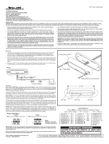
Insert slide bolts into base,slide them across to their mounting
position and secure them with the set screws
2.
2.
1. Remove one lightbar endcap.
Slide Bolt Mounting:
Drill the four holes with an appropriately sized drill bit4.
Replace end cap. Insert bolts into their 4 mounting holes. Secure
the lightbar with the supplied hardware
5.
5.
Position the lightbar onto the vehicle and mark the four bolt hole
locations on the mounting surface
3.
3.
Insert into
the base here.
Tighten both set screws
to secure to base
Mounting
Pad
Mounting
Pad
Adjustable
Mounting
Foot
Washer
Washer
Nut
Nut
BoltBolt
Mounting
Plate
Mounting
Plate
Standard
Mounting
Foot
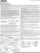
NOTE: Unless otherwise specified, the lightbar mounting feet must be sitting as close to the edge of the roof as possible. They must also be
in full contact with the roof and not be hanging off the edge.
IMPORTANT: For strap mounting, be sure you have the right sized
lightbar for your vehicle. The bar should be approximately the same
width as the vehicle roof. If too large or small it will not mount properly
and may come loose during driving.
1/2" MIN. CLEARANCE
Permanent Mounting:
1. Locate the mounting foot and mounting plate included with your lightbar. If not already present, install the
mounting plate onto the mounting foot. When properly positioned, this plate is centered from side to side
on the mounting foot.
2. Flip lightbar upside-down to expose bottom of extrusion and place mounting foot onto
extrusion.
3. Rotate the mounting foot 90° in a counter-clockwise direction. Make sure that the
edges of the mounting foot swing into position under the extrusion mounting lip.
4. Repeat this procedure for the remaining mounting foot and return the lightbar to its right
side-up position.
5. Position the lightbar onto the vehicle roof in the desired mounting location. One often
selected location is directly above the B-pillars. This area is the strongest part of the
roof. Refer to your lightbar manual for your lightbars cable exit location, to be sure that
the lightbar is facing the proper direction.
6. Adjust the two mounting feet outwards so that they are as close to the edge of the roof
as possible. Make sure that both mounting feet are in full contact with the roof (See
below). Be sure that there is no less than 1/2” clearance between the roof and the
lightbar at their closest point. When the mounting feet are in their proper position, lightly
tighten the mounting foot allen head set screws.
7. Turn the lightbar upside down and firmly tighten all of the set screws from step 6 (2 or 4
per side).
8. On the mounting foot, remove either the two outer or inner rubber mounting pads. Carefully
remove the mounting pad’s guide dart so the hole through the center of the pad is exposed then
replace the pad (Standard foot only). On the adjustable foot, use the hole in the pad as a guide to drill
the two holes into the mounting foot.
9. Place the lightbar in its final mounting position on
the vehicle, mark the mounting hole locations off
onto the mounting surface, remove the lightbar and
drill the mounting holes.
10. Place the lightbar back onto the vehicle lined up
with the mounting holes and secure the mounting
feet to the vehicle using the supplied hardware.
Slide Bolt Mounting (Permanent):
This lightbar mounts with 4 bolts affixed to mounting plates that slide into the track on the bottom of the lighbar base. Figures 1 and 1a show how the slide bolt assembly slides
into your lightbars base and mounts onto the vehicle. Use an appropriately sized drill bit sized for a 1/2 - #13 X 2” bolt, to drill the mounting holes.
Strap Mounting:
1. Locate the mounting foot, mounting plate and tinnerman plate included with
your lightbar. If not already present, install the mounting plate onto the
mounting foot. When properly positioned, this plate is centered from side to
side on the mounting foot.
2. Flip the lightbar upside-down to expose the bottom of the extrusion and place
the mounting foot onto the extrusion.
3. Rotate the mounting foot 90° in a counter-clockwise direction. Make sure that
the edges of the mounting foot swing into position under
the extrusion mounting lip. Install a tinnerman plate onto
the extrusion in the same manner.
4. Repeat this procedure for the
remaining mounting foot and
tinnerman plate and return the
lightbar to its right side-up position.
5. Position the lightbar onto the vehicle roof in the desired mounting location. One
often selected location is directly above the B-pillars. This area is the strongest
part of the roof. Refer to your lightbar manual for cable exit location, to be sure
that the lightbar is facing the proper direction.
6. Adjust the two mounting feet outwards so that they are as close to the edge of
the roof as possible. Both mounting feet must be in full contact with the roof. Be
sure that there is no less than 1/2” clearance
between the roof and the lightbar at their
closest point. When the mounting feet are in
their proper position, lightly tighten the
mounting foot allen head set screws.
7. Return the lightbar to an upside down
position. Slide each tinnerman plate
outwards until it is fully engaged with its
corresponding mounting foot. With the
mounting feet and tinnerman plates in their
proper positions firmly tighten all of the set
screws (2 or 4 per side). Flip the lightbar
right side-up and return it to its mounting
position.
FRONT
Driver-side
cable exit
Passngr.-side
cable exit
Cable Access Hole
Drill the cable access hole in the
appropriate area for your lightbar.

Page 3
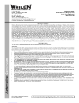
MOUNTING FOOT
TINNERMAN
NUT
FOOT
ANCHOR
PLATE
SET
SCREW
Plate slides into
lightbar extrusion
5" Mounting Foot
NUT
BOLT
SPLIT LOCK
WASHER
METAL SCREW
NOTE: The mounting straps are made to fit the contours of individual
vehicles. The strap
may look different.
shown here is for example only. The strap
for your vehicle
NOTE:
NOTE:
STRAP
SHEET
METAL
SCREWS
EXTENSION
VEHICLE ROOF
Tinnerman
Plate Locking
Plate
Mounting
Plate
Mounting
Foot
Nut
Mounting
Pad
Adjustment
screws
Lock
Washer
Mounting
Foot
Mounting
Pad
Tinnerman
Plate
Mounting
Strap
Mounting
Screw
Tension
Bolt
Adjustable Mounting Foot / Model MKAJ
Standard Mounting Foot / Model MKEZ
Tighten screws
with torque wrench
set at 35 to 40 in/lbs
Mounting
Strap
Mounting
Screw
Tension
Bolt
8. Open both drivers side doors. In the area directly below the mounting foot,
carefully pull the drivers side weather-strip away from the vehicle. Remove
enough so that the area where the mounting strap will be secured to the
vehicle is exposed. Repeat procedure for passenger side.
9. Insert the mounting strap through the mounting foot. Be sure that the strap fits
flush against the area where it will be secured onto the vehicle. Insert the
tension bolt through the mounting strap and into the tinnerman nut on the
tinnerman plate. Tighten slightly with a long shafted, Phillips screwdriver.
Repeat procedure for passenger side.
10. If your mounting strap has mounting holes in the end of the strap, use these
holes as a template to drill appropriately sized pilot holes through the strap and
into the vehicle. Repeat for passenger side of the vehicle.
11. Firmly tighten the tension bolts to secure the lightbar to the vehicle.
NOTE: Model MKAJ is an adjustable mounting foot. On this model you may
loosen the screws on the rear of the foot and adjust the angle of the lightbar.
This feature can be used if the angle of the roof is not level with the road.
IMPORTANT: To adjust the leveling screws you must use a torque wrench set
at 35 to 40 ft. lbs.
Lightbar Cables:
Standard Lightbar: This lightbar uses a 4 conductor cable for LED’s, a 6 conductor
cable for Halogen and a 3 conductor cable for Options. There is also an option for
Brake-Tail to connect to your brake lights. Extend the 3, 4 and 6 conductor cables
towards your switch panel. The instructions included with your switches will provide
switch wiring information. The optional brake-tail cable connects to the brake lights.
Refer to the next page for wire designations and fusing.
WARNING! All Customer supplied wires that connect to the positive terminal of
the battery must be sized to supply at least 125% of the maximum operating
current and FUSED at the battery to carry that load. DO NOT USE CIRCUIT
BREAKERS WITH THIS PRODUCT!
Halogen Cable:
WHITE: Apply +12 volts to activate the TakeDowns or Worklight
GREEN: Apply +12 volts to activate the Passenger Side Alley lights
RED: Apply +12 volts to activate the Driver Side Alley light.
BLUE: Apply +12 volts to activate the Takedowns in flashing mode.
Options Cable:
RED: ScanLock™
LED’s must be on for ScanLock™ to work.
TO CHANGE PATTERNS: To cycle forward to
the next available pattern: Apply +12 volts to
the ScanLock™ wire for less than 1 second
and release. To cycle back to the previous
pattern: Apply +12 volts to the ScanLock™ wire for more than 1 second and release.
TO CHANGE THE DEFAULT PATTERN: When the desired pattern is active, allow it
to run for more than 5 seconds. The lighthead will now display this pattern when
activated.
TO RESTORE THE FACTORY DEFAULT PATTERN: With power to the lightheads
off, apply +12 volts to the ScanLock™ wire. While still applying +12 volts to the Scan-
Lock™ wire, turn power to the lightheads back on. The factory default pattern should
now be displayed.
A Normally Open momentary switch can be used to control Scan-Lock™
operation.
Installation: If your lightbar has a 5” mounting foot, it will assemble
differently than the standard mounting foot. It also uses an
extension to compensate for the extra height. Follow these
illustrations for assembly. Mounting to the lightbar is the same.
CAUTION! DO NOT LOOK DIRECTLY AT THESE LED’S WHILE THEY ARE ON.
MOMENTARY BLINDNESS AND/OR EYE DAMAGE COULD RESULT!
IMPORTANT WARNING!

Page 4
MR11's can be adjusted up to 7.5 to either side.°
Remove dome
MR-11 Halogen / Angle Adjustment
The MR11 mounting brackets angle is adjustable
An alley light is shown here.
MR11 / Removal & Installation / Alley Light
CAUTION! Replacing any halogen bulb requires the use of safety glasses to prevent injury.
! Do not handle the bulb with bare hands. Use gloves to prevent possible injury.CAUTION
T-10
Torx
Head
Remove
dome
screws
(QTY 4)
Remove screws
and pull housing
part way out.
3
1
2
Pry housing slightly apart
to remove bulb
4
5
Replace Bulb
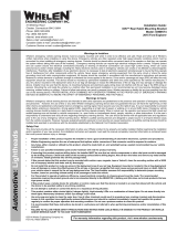
HALOGEN
WHITE .
GREEN
RED
BLACK
ORANGE
BLUE
Steady T.D./Worklt
Pass. Alley
Driver Alley
Take-Down
Alley
Flashing Takedown
(+)12V
(+)12V
(+)12V
(-)
(+)12V
Ground
Ground
(-)
Fuse @ 7.5 Amps
Fuse @ 3
Fuse @ 3
Amps
Amps
Neg. (-)B
attery
Neg. (-)B
attery
Fuse @ 7.5 Amps
Justice™Competitor Series Lightbar
OPTIONS
GREEN
RED
BLACK
Not Used
ScanLock™
Pattern Override
(+)12V
(+)12V
Fuse @
Fuse @ 1
1 Amp
Amp
BRAKE-TAIL
WHITE
GREEN
RED
BLACK
Tail
PS Brake
DS Brake
(-)
(+)12V
(+)12V
(+)12V
Ground
Fuse @ 1 Amp
Fuse @ 1 Amp
Fuse @ 1 Amp
Neg. (-)B
attery
LED's
RED
BLACK
RED/WHT
Front LED's
Front LED's
Rear LED's
BLK/WHT
(+)12V
Ground (-)
(+)12V
Ground (-)Rear LED's
Fuse @ 10 Amps
Neg. (-)B
attery
Fuse @ 10 Amps
Neg. (-)B
attery
BLACK: Pattern Override
Applying +12 volts to the BLACK wire while lightheads are activated will change the
flash pattern to whatever “pattern override” is programmed for. To program the flash
pattern activate the lightbar. Activate pattern override by applying +12 volts to the
BLACK wire then select a flash pattern using the Scan-Lock™ procedure.
IMPORTANT! Before returning this vehicle to active service, visually confirm
the proper operation of this product, as well as all vehicle components/
equipment.
IMPORTANT! It is the responsibility of the installation technician to make sure
that the installation and operation of this product will not interfere with or
compromise the operation or efficiency of any vehicle equipment!
Available Flash Patterns:
1. ActionScan™
2. SignalAlert™ Alt.
3. SignalAlert™ Alt./ASync
4. SignalAlert™Sim.
5. SignalAlert™ Alt./Sim.
6. CometFlash® Alt.
7. CometFlash® Alt./ASync
8. CometFlash® Sim.
9. CometFlash® Alt./Sim.
10. DoubleFlash 75 Alt.
11. DoubleFlash 75 Alt./ASync
12. DoubleFlash 75 Sim.
13. DoubleFlash 75 Alt./Sim.
14. SingleFlash 75* Alt.
15. SingleFlash 75* Alt./ASync
16. SingleFlash 75* Sim.
17. SingleFlash 75* Alt.Sim.
18. LongBurst™ Alt.
19. LongBurst™ Alt./ASync.
20. LongBurst™ Sim.
21. LongBurst™ Alt./Sim.
22. SingleFlash 60* Alt.
23. SingleFlash 60* Alt./ASync.
24. SingleFlash 60* Sim.
25. SingleFlash 60* Alt./Sim.
26. SingleFlash 90* Alt.
27. SingleFlash 90* Alt./Sync.
28. SingleFlash 90* Sim.
29. SingleFlash 90* Alt./Sim.
30. SingleFlash 120* Alt.
31. SingleFlash 120* Alt./Sync.
32. SingleFlash 120* Sim.
33. SingleFlash 120* Alt./Sim.
34. SingleFlash 300 Alt.
35. SingleFlash 300 Alt./Sync.
36. SingleFlash 300 Sim.
37. SingleFlash 300 Alt./Sim.
38. MicroBurst™ Alt.
39. MicroBurst™ Alt./ASync.
40. MicroBurst™ Sim.
41. MicroBurst™ Alt./Sim.
42. ActionFlash™ Alt.
43. ActionFlash™ Alt./ASync.
44. ActionFlash™ Sim.
45. PingPong Alt.
46. PingPong Alt./ASync.
47. FlimFlam Alt.
48. FlimFlam Alt./ASync.
49. ModuFlash™ Alt.
50. ModuFlash™ Alt./ASync.
51. ModuFlash™ Sim.
52. ZigZag.
Alt.= Alternating Sim. = Simultaneous Alt./Sim. = Alternating/Simultaneous
Alt./ASync. = Alternating/ASynchroneous * = California Title IIIX Compliant
/