Page is loading ...

Life Alarm
Fire Alarm Systems
Fire Alarm Controls
4001-9304C
FEATURES
•
Four monitor zones
•
Up to 18 two-wire smoke detectors per zone
•
Signal circuits — 2 class B or 1 class A —
field configurable
•
Selectable alarm verification
•
Self-contained audible trouble signal
•
One normally open city contact
•
One form C alarm auxiliary contact
•
One form C trouble contact
•
Transient suppression for municipal
connections on power supply
•
Automatic battery charger
•
Standby batteries
• Surface or semi-flush mounting
•
Alarm/trouble system walk test
•
Alarm resound
•
Battery supervision
•
Earth ground supervision
•
Brown out supervision of AC power
•
Automatic signal silence
•
DIP switch selectable programming
•
End-of-line devices and batteries included
•
ULC Listed to CAN-ULC-S527-99
®
©2003 SimplexGrinnell Canada Ltd. S01575-110-2 10/03
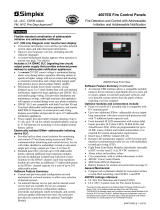
Simplex
®
ZONE
ALARM
TROUBLE
TROUBLE
AC POWER ON
ALIMENTATION
SYSTEM TROUBLE
TROUBLE SYSTEM
SIGNALS SILENCED
ARRET ALARME
ALARME
ZONE
1
2
3
4
FIRE ALARM CONTROL
PANNEAU DE CONTROLE AVERTISSEUR D’INCENDIE
4001-9304C
OPTIONS
•
Option Board - supervised annunciator output
- auxiliary resettable power
- non-silenceable trouble contact
•
Semi-flush trim kit
•
External battery & cabinet for 60 hour backup
SPECIFICATIONS
Input ..................................1.2A @ 120VAC 60 Hz
Humidity.................85% non-condensing @ 30°C
Temperature .......................................0°C to 49°C
Weight...............Approximately 10kg c/w batteries
Colour ..........................................................Beige
Knockouts .......................................................1/2”
ULC Listed

OPERATOR INTERFACE SWITCHES
•
Signals Silence
•
System Reset
•
Trouble Silence
•
Alarm Auxiliary Disconnect
•
Drill
LED INDICATORS
•
Green AC Power On
•
Yellow Power Trouble
•
Yellow System Trouble
•
Yellow Earth Trouble
•
Red Alarm for Each Zone
•
Yellow Trouble for Each Zone
•
Yellow Signal Circuit Trouble
•
Yellow Signals Silenced Trouble
2
ZONE
ZONE
ALARM
ALARME
TROUBLE
TROUBLE
1
AC POWER ON
ALIMENTATION
SYSTEM TROUBLE
SIGNALS SILENCED
ARRET ALARME
CAUTION
FOR SERVICE ONLY
120 VAC ACROSS
TERMINALS
ATTENTION
120 VCA ENTRE
LES BORNES
ALARM
AUXILIARY
DISCONNECT
DRILL
SIGNALS
SILENCE
SYSTEM
RESET
DEBRANCHEMENT
AUXILIAIRE
DE L'ALARME
TROUBLE
REMISE
SYSTEME
ARRET
ALARME
REPLACE COVER AFTER SERVICE LE REMETTRE UNE FOIS L'ENTRETIEN TERMINE
POUR L'ENTRETIEN SEULEMENT
ATTENTION
REMOVE COVER ENLEVER LE REVETEMENT
TROUBLE SYSTEME
EXERCICE
TROUBLE
ARRET
SILENCE
2
3
4
TB1
F1
SW4
F2
F3
F4
TB2
+24
OV
+5
TB3
TP4
B
A
T-
B
A
T
+
X
F
M
R
X
F
M
R
S
I
G
A
+
S
I
GB
-
S
I
G
A
-
S
I
GB
+
Z
1+
Z
1-
Z
2
+
Z
2-
Z
3+
Z
3-
Z
4+
Z
4
-
NO
C
N
C
N
O
C
NC
N
O
C
TP1
TP5
H1
POT1
POT2
TB4
TP3
TP2
TP6
1
2
3
4
5
6
1
10
123
654
H2
0V
R
P
W
R
GN
D
GND
5A
2A
2A
6A
3.3k,1W,5%
+
-
2A@30VAC/VDC
10k,1/2W,5%10k,1/2W,5%
+
++
+
+-+-
LGN
T1
120V60HZ
1.2A
POWERSUPPLY
TROUBLE
BROWN
OUT
TROUBLE
EARTH
OPERATOR’S PANEL

DIP SWITCH SELECTABLE PROGRAMMING
SYSTEM WALK TEST — Activating an initiating de
-
vice will cause the indicating appliance to signal a
simple code (zone number) without actuating the
municipal connection or auxiliary alarm outputs and
will then automatically reset. Momentarily opening a
monitor zone or signal circuit will cause the indicat
-
ing appliance to operate for 4 seconds, thereby
testing electrical supervision.
ALARM VERIFICATION — Activation of any smoke
detector will initiate an alarm verification cycle. The
control will retard the activation of the indicating ap
-
pliances for 30 seconds. During this delay, if any
other device activates, the alarm will be confirmed
and the indicating appliances energized. If a second
device does not activate during the 30-second delay,
the control will reset and begin a 60-second confir
-
mation cycle. During the confirmation cycle, should
any device alarm, on any zone, the indicating appli
-
ance circuit will energize. Should the verification
cycle end without “incident” the panel will return to its
normal state. Manual stations, heat detectors, and
waterflow switches will always cause the fire alarm
control to activate immediately.
TEMPORAL PATTERN — Causes the indicating ap
-
pliances to sound the temporal pattern.
ALARM SILENCE INHIBIT — Disables the signals
silence and system reset switches for 1 or 3 minutes.
AUTOMATIC SIGNAL SILENCE — Silences the
alarm signals after 20 minutes.
3
TB1
F1
SW4
F2
F3
F4
TB2
+24
OV
+5
TB3
TP4
BAT-
BAT+
XFMR
XFMR
SIGA+
SIGB-
SIGA-
SIGB+
Z1+
Z1-
Z2+
Z2-
Z3+
Z3-
Z4+
Z4-
NO
C
NC
NO
C
NC
NO
C
TP1
TP5
H1
POT1
POT2
TB4
TP3
TP2
TP6
1
2
3
4
5
6
1
10
12 3
654
H2
0V
RPWR
GND
GND
5A
2A
2A
6A
3.3k, 1W, 5%
+
-
2A @ 30 VAC / VDC
10k, 1/2W, 5%10k, 1/2W, 5%
+
++
+
+-+ -
LGN
T1
120V 60HZ
1.2A
POWER SUPPLY
TROUBLE
BROWN
OUT
TROUBLE
EARTH
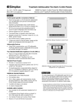
TYPICAL 4001-9304C SYSTEM LAYOUT
TYPICAL WIRING CONNECTIONS. FOR MORE DETAILED WIRING INSTRUCTIONS, REFER TO
OPERATION AND INSTALLATION INSTRUCTIONS, S01575-109.

FEATURE SELECTION CHART
PID
DESCRIPTION
4001-9304C 4 Zone Control, 120VAC Input, c/w batteries & End-of-Line Resistors
4001-9850C Option Board Kit
2975-9801 Semi-Flush Trim Kit
4009-9801 &
2081-9275
External Battery Cabinet &
18 Ah Battery (order [2] 2081-9275)
®
2400 Skymark Avenue, Mississauga, ON L4W 5K5
Offices and Representatives Throughout the World
Visit us on the World Wide Web @ www.simplexgrinnell.com
All specifications and other information shown were current as of printing and are subject to change without notice.
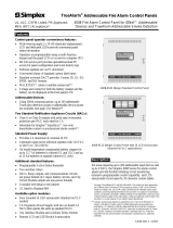
(TOP)
(BOTTOM)
NO WIRE
ENTRY
BATTERIES
ONLY
SEMI-FLUSH MOUNT
LEFT SIDE
SURFACE MOUNT
RIGHT SIDE
13”
4”
10.5”
3”
4”
/