Interlogix TVR-6016-500 User manual
- Category
- Digital Video Recorders (DVR)
- Type
- User manual
This manual is also suitable for

TruVision DVR 60 User
Manual
P/N 1069895F-EN • REV 6.0 • ISS 10MAY11

Copyright © 2011 UTC Fire & Security. All rights reserved.
Trademarks and patents Interlogix, TruVision and logos are trademarks of UTC Fire & Security.
Other trade names used in this document may be trademarks or registered
trademarks of the manufacturers or vendors of the respective products.
Manufacture
r
UTC Fire & Security Americas Corporation, Inc.
2955 Red Hill Avenue, Costa Mesa, CA 92626-5923, USA
Authorized EU manufacturing representative:
UTC Fire & Security B.V.
Kelvinstraat 7, 6003 DH Weert, The Netherlands
Certification
FCC compliance Class A: This equipment has been tested and found to comply with the limits for
a Class A digital device, pursuant to part 15 of the FCC Rules. These limits are
designed to provide reasonable protection against harmful interference when the
equipment is operated in a commercial environment. This equipment generates,
uses, and can radiate radio frequency energy and, if not installed and used in
accordance with the instruction manual, may cause harmful interference to radio
communications. Operation of this equipment in a residential area is likely to
cause harmful interference in which case the user will be required to correct the
interference at his own expense.
ACMA compliance Notice! This is a Class A product. In a domestic environment this product may
cause radio interference in which case the user may be required to take
adequate measures.
Canada This Class A digital apparatus complies with Canadian ICES-003.
Cet appareil numérique de la classe A est conforme à la norme NMB-0330 du
Canada.
European Union directives 12004/108/EC (EMC directive): Hereby, UTC Fire & Security declares that this
device is in compliance with the essential requirements and other relevant
provisions of Directive 2004/108/EC.
2002/96/EC (WEEE directive): Products marked with this symbol cannot be
disposed of as unsorted municipal waste in the European Union. For proper
recycling, return this product to your local supplier upon the purchase of
equivalent new equipment, or dispose of it at designated collection points. For
more information see: www.recyclethis.info.
2006/66/EC (battery directive): This product contains a battery that cannot be
disposed of as unsorted municipal waste in the European Union. See the product
documentation for specific battery information. The battery is marked with this
symbol, which may include lettering to indicate cadmium (Cd), lead (Pb), or
mercury (Hg). For proper recycling, return the battery to your supplier or to a
designated collection point. For more information see: www.recyclethis.info.
Contact information www.interlogix.com
www.utcfssecurityproducts.eu
Customer support www.interlogix.com/customer-support

TruVision DVR 60 User Manual i
Content
Chapter 1 Product introduction 1
Product overview 1
Features 2
Chapter 2 Installation 5
Installation environment 5
Unpacking the TVR 60 and its accessories 5
HDD capacity 6
Connecting devices to the rear panel 6
IP cameras supported 7
PTZ dome camera set up 8
Wiring the keypad 12
RS-485 ports 14
RS-232 port 15
Monitor connections 15
Loop through 15
Audio inputs and output 15
Brackets 16
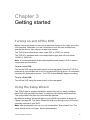
Chapter 3 Getting started 19
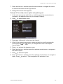
Turning on and off the DVR 19
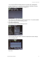
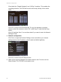
Using the Setup Wizard 19
Chapter 4 Operating instructions 23
Controlling the TVR 60 23
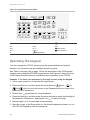
Using the front panel 23
Using the mouse 25
Using the IR remote control 26
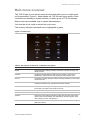
Main menu overview 29
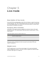
Chapter 5 Live mode 33
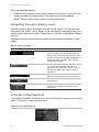
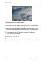
Description of live mode 33
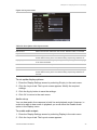
Digital zoom 33
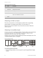
Switching monitors 34
Pop-up menus for mouse operation 35
Viewing in full screen 36
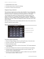
Viewing in multiscreen 36
Sequencing cameras in live mode 37
Cameo shortcuts 37
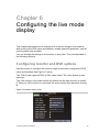
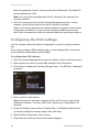
Chapter 6 Configuring the live mode display 39
Configuring monitor and DVR options 39
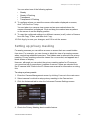
Configuring time and date 41

ii TruVision DVR 60 User Manual
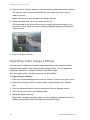
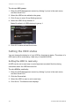
Configuring display options 42
Chapter 7 Controlling a PTZ dome camera 47
Configuring PTZ settings 47
Pop-up menu for mouse operation 49
Setting presets, preset tours and shadow tours 49
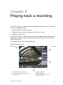
Chapter 8 Playing back a recording 55
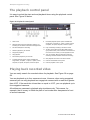
The playback control panel 56
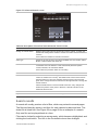
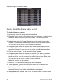
Playing back recorded video 56
Exiting playback mode 63
Chapter 9 Archiving recorded files 65
Archiving files 65
Archiving video clips 68
Managing backup devices 68
Playing back archived files on a PC 69
Chapter 10 Using the Web browser 71
Windows Vista and 7 users 71
Accessing the Web browser 72
Web browser overview 72
Using the Web browser to configure the device 74
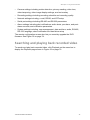
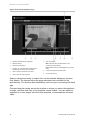
Searching and playing back recorded video 75
Searching for event logs 77
Live dual streaming 77
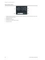
Controlling a PTZ dome camera in the Web browser 77
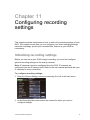
Chapter 11 Configuring recording settings 79
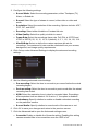
Initializing recording settings 79
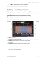
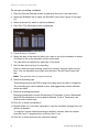
Defining a recording schedule 81
Protecting recorded files 83
Configuring advanced HDD settings 84
Chapter 12 Configuring alarm settings 87
Motion detection 87
Setting up external alarms 92
Triggering alarm outputs manually 94
Setting up system notifications 95
Detecting video loss 96
Detecting video tampering 97
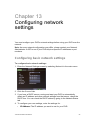
Chapter 13 Configuring network settings 99
Configuring basic network settings 99
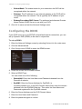
Configuring the DDNS 100
Configuring an NTP server 101
Configuring a remote alarm host 101
Configuring multicast 102

TruVision DVR 60 User Manual iii
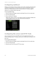
Configuring the server and HTTP Ports 102
Configuring e-mail settings 103
Chapter 14 Camera management 105
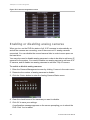
Enabling or disabling analog cameras 106
Configuring IP cameras 107
Configuring the OSD settings 108
Setting up privacy masking 109
Adjusting video image settings 110
Chapter 15 HDD management 113
Initializing HDDs 113
Setting HDD groups 113
Setting the HDD status 114
Checking HDD status 116
Configuring HDD alarms 117
Chapter 16 Configuring the DVR settings 119
Changing the language 119
Managing users 119
Updating system firmware 125
Restoring default settings 127
Viewing system information 127
Viewing system logs 127
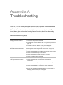
Appendix A Troubleshooting 129
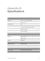
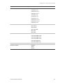
Appendix B Specifications 131
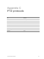
Appendix C PTZ protocols 135
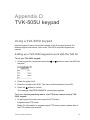
Appendix D TVK-505U keypad 137
Using a TVK-505U keypad 137
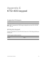
Appendix E KTD-405 keypad 139
Supported firmware 139
Wiring the keypad 139
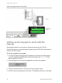
Setting up the keypad to work with the TVR 60 140
Operating the keypad 142
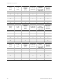
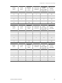
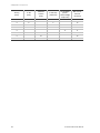
Appendix F Camera matrix 149
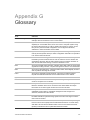
Appendix G Glossary 153
Index 155
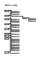
Menu map 158

iv TruVision DVR 60 User Manual

TruVision DVR 60 User Manual 1
Chapter 1
Product introduction
Product overview
This is the TruVision DVR 60 User Manual for models:
Table 1: Product codes
Product code EMEA Americas
TVR-6016-500 Available Unavailable
TVR-6016-1T Available Unavailable
TVR-6016-2T Available Available
TVR-6016-4T Available Available
TVR-6016-8T Available Available
TVR-6016-12T Available Available
Note: Some model versions are not available across all regions. EMEA product
codes end with “EA” and are shipped with UK and European power cords.
The TruVision™ DVR 60 (TVR 60) is a full featured and scalable hybrid digital
video recording system with the ability to store, display live, search, and transmit
video from up to 24 analog or IP cameras.
Its dual streaming functionality allows the user to set up different settings for
recording and streaming video in live mode.
TruVision DVR 60 can fully integrate with the license-free TruVision Navigator
software, which is ideal for the most commercial applications. TVR 60’s easy and
intuitive-to-use web browser interface enables remote configuration and secure
viewing, searching, and playing back of video from computers connected via the
Internet.

0BChapter 1: Product introduction
2 TruVision DVR 60 User Manual
Features
This section describes the available TVR 60 features.
Compression
The TVR 60 supports the following video features:
• Scalable state-of-the-art hybrid H.264 video compression algorithm
• Supports both analog and IP cameras
• Real-time recording of 24 channels at 4CIF resolution
• Supports watermarking.
Storage
The TVR 60 supports the following storage features:
• Supports up to 12TB of onboard storage
• Supports configurable redundant recording
• Supports HDD designed for 24 × 7 operation and high write duty cycles
• Camera to HDD assignment for HDD data grouping
Recording and playback:
The TVR 60 supports the following video features:
• Real-time recording of 24 channels at 4CIF resolution
• Supported IP devices: TruVision H.264 MPX and SD IP cameras, UltraView
Encoder 10, UltraView IP, CamPlus2 IP and Panasonic IP cameras
• Dual streaming functionality allows the use of different settings for recording
and streaming video
• PTZ and dome camera control via mouse, front panel joystick and IR remote
controller
• E-mail notification upon alarm with attached images and health notifications
Network
The TVR 60 supports the following video features:
• Networkable via Ethernet (TCP/IP) for remote monitoring, searching,
playback, archiving, configuration, alarm notifications and firmware upgrades
• Ability to fully integrate with the license-free TruVision Navigator software and
TVRmobile software.
• Built-in Web server
Other:
The TVR 60 supports the following additional features:

0BChapter 1: Product introduction
TruVision DVR 60 User Manual 3
• Auto-detect video (PAL or NTSC) on startup
• Multiple control inputs: front panel, mouse, IR remote control, and keyboard
• Supports KTD-405 / TVK-505U keypad control
• Multi-language support
• Triple monitor support - Monitor A, monitor B and spot monitors

0BChapter 1: Product introduction
4 TruVision DVR 60 User Manual

TruVision DVR 60 User Manual 5
Chapter 2
Installation
Installation environment
When installing your product, consider these factors:
• Ventilation
• Temperature
• Moisture
• Chassis load
Ventilation: Do not block any ventilation openings. Install in accordance with the
manufacturer’s instructions. Ensure that the location planned for the installation
of the unit is well ventilated.
Temperature: Consider the unit’s operating temperature (0 to 40°C, 32 to 104°F)
and noncondensing humidity specifications (10 to 90%) before choosing an
installation location. Extremes of heat or cold beyond the specified operating
temperature limits may reduce the life expectancy of the TruVision DVR 60. Do
not install the unit on top of other hot equipment. Leave 44 mm (1.75 in.) of
space between rack-mounted TruVision DVR 60 units.
Moisture: Do not use the unit near water. Moisture can damage the internal
components. To reduce the risk of fire or electric shock, do not expose this unit to
rain or moisture.
Chassis: Equipment weighing less than 15.9 kg (35 lb.) may be placed on top of
the unit.
Unpacking the TVR 60 and its accessories
When you receive the product, check the package and contents for damage, and
verify that all items are included. There is an item list included in the package. If
any of the items are damaged or missing, please contact your local supplier.
Items shipped with the product include:

1BChapter 2: Installation
6 TruVision DVR 60 User Manual
• IR (infrared) remote control
• Two AAA batteries for the remote control
• AC power cords (US, Europe, UK)
• USB mouse
• DVR
• Video loop through cable
• TruVision DVR 60 Quick Start Guide
• TruVision DVR 60 User Manual (on CD)
HDD capacity
Storage capacity for the TVR 60 varies depending on the model. Refer to Table 2
below for more information.
Table 2: TruVision DVR 60 model types
Model number Description
TVR-6016-500EA TruVision DVR Model 60, 16 ch, 500 GB
TVR-6016-1TEA TruVision DVR Model 60, 16 ch, 1 TB
TVR-6016-2T(EA) TruVision DVR Model 60, 16 ch, 2 TB
TVR-6016-4T(EA) TruVision DVR Model 60, 16 ch, 4 TB
TVR-6016-8T(EA) TruVision DVR Model 60, 16 ch, 8 TB
TVR-6016-12T(EA) TruVision DVR Model 60, 16 ch, 12 TB
Connecting devices to the rear panel
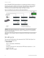
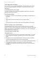
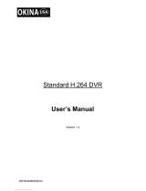
Figure 1 below shows the rear panel connections and describes each connector
on a typical TVR 60 digital video recorder. Details may vary for specific models.
Before powering up the DVR, connect the cameras and a main monitor for basic
operation.

1BChapter 2: Installation
TruVision DVR 60 User Manual 7
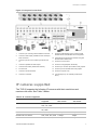
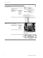
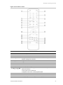
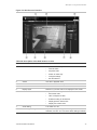
Figure 1: Rear panel connections
1. Connect up to 16 analog cameras to BNC connectors.
2. Connect to audio inputs (available for each camera) to
RCA connectors.
3. Connect up to two CCTV monitors (monitors B and
C).
4. Connect to speakers for audio output.
5. Connect VGA monitor (default main monitor).
6. For future use.
7. Connect to an eSATA device.
8. Connect to a network.
9. Connect to USB devices such as a mouse. USB
CD/DVD burner and USB HDD are not supported.
10. Terminate the line to the dome cameras using this
RS-485 switch. Default is Off.
11. Connect to a PTZ control.
12. Connect to a keypad (KTD-405 shown)
13. Connect up to 16 alarm input cables to relay outputs.
14. Connect up to four NO/NC alarm relay outputs.
15. Connect to a power cord.
16. Loop through for up to 16 analog cameras (see
item 1).
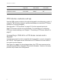
IP cameras supported
The TVR 60 supports the following IP cameras with their resolutions and
maximum bit rates. See Table 3 below.
Table 3: IP cameras supported
Supported cameras Resolutions
supported Maximum bit rate -
Main stream Maximum bit rate
- Sub stream
TruVision 2MPX camera UXGA, HD720P, 4CIF,
2CIF, CIF, QCIF
2Mbps 1Mbps
TruVision 1.3MPX camera HD720P, 4CIF, 2CIF,
CIF, QCIF
2Mbps 1Mbps
UltraView encoder 4CIF, 2CIF, CIF, QCIF 1.7Mbps 1Mbps
UltraView IP box camera 4CIF, 2CIF, CIF, QCIF 1.7Mbps 1Mbps
UltraView IP dome camera 4CIF, 2CIF, CIF, QCIF 1.7Mbps 1Mbps

1BChapter 2: Installation
8 TruVision DVR 60 User Manual
Supported cameras Resolutions
supported Maximum bit rate -
Main stream Maximum bit rate
- Sub stream
UltraView IP PTZ camera 4CIF, 2CIF, CIF, QCIF 1.7Mbps 1Mbps
CamPlus2 IP camera VGA, QVGA 2Mbps N/A
Panasonic IP camera VGA, QVGA 2Mbps N/A
PTZ dome camera set up
Use the USB mouse provided or the optional keypad for local telemetry control. If
using the TVR 60 over a network, use the web browser to control the PTZ dome
cameras or TruVision Navigator.
See Appendix C “PTZ protocols” on page 135 for the supported protocols.
Each PTZ camera must be set up individually. For information on configuring
PTZ dome camera settings, see Chapter 7 “Controlling a PTZ dome camera” on
page 47.
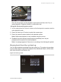
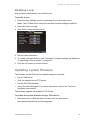
Connecting a TVR 60 to a PTZ dome camera and a
keypad
Use the input/output box that is supplied with the keypad to connect a keypad to
the TVR 60. The keypad can be connected to a PTZ camera for local control or
for control over the network.
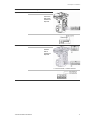
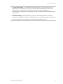
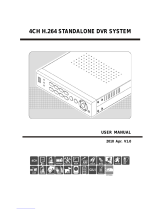
See Figure 2 on page 9 for the preferred setup. Any PTZ dome camera can be
controlled as the DVR is doing the PTZ protocol translation. However, this setup
provides only limited dome configuration.

1BChapter 2: Installation
TruVision DVR 60 User Manual 9
Figure 2: Connecting a keypad to the TVR 60 for control of a PTZ dome camera over the
network
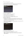
Configuring the PTZ protocols for Interlogix cameras
Before the PTZ dome cameras are assembled in their housings, set their
protocol and address DIP switches for the TVR 60. See Table 4 below for
different Interlogix PTZ dome camera settings.
If you are using PTZ dome cameras from another company, please refer to their
configuration instructions.
Table 4: PTZ protocols for Interlogix cameras
Camera Switch setting
TruVision Mini PTZ
12X: Indoor Dome
Protocol DIP switches: 000000
RS-485
communication DIP
switches:
0000000000
Camera ID DIP
switches:
Select the
camera ID
DIP switch
address as
required
1. Protocol DIP switches
2. RS-485 communication DIP switches
3. Camera ID DIP switches
RS-485 data connector:

1BChapter 2: Installation
10 TruVision DVR 60 User Manual
Camera Switch setting
TruVision Mini PTZ
12X: Outdoor Dome
Protocol DIP switches: 000000
RS-485
communication DIP
switches:
0000000000
Camera ID DIP
switches:
Select the
camera ID
DIP switch
address as
required.
1. Protocol DIP switches
2. RS-485 communication DIP switches
3. Camera ID DIP switches
RS-485 data connector:
TruVision Dome 16X
PTZ
Protocol switches: 0111
Address switches: Select the
camera ID
DIP switch
address as
required.
Baud rate: 0000
1. Address switches; 2. Baud switches;
3. Protocol switches
RS-485 data connector:

1BChapter 2: Installation
TruVision DVR 60 User Manual 11
Camera Switch setting
CyberDome Protocol switches: NA
Address switches: Select the
camera ID
DIP switch
address as
required.
RS-485 data connector:
UltraView PTZ Protocol switches: 01000
Address switches: Select the
address
switch
address as
required.
1. Protocol switches; 2. Address switches
RS-485 data connector:

1BChapter 2: Installation
12 TruVision DVR 60 User Manual
Camera Switch setting
Legend Protocol switches: 1
Address switches: Select the
camera ID
DIP switch
address as
required.
RS-485 data connector:
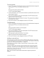
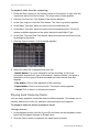
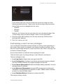
Wiring the keypad
The keypad uses RS-485 simplex wiring. The signal is transferred by a single
twisted pair line. A shielded STP CAT5 network cable is recommended. Ground
one end of the cable, either the first or last device on the RS-485 line.
The maximum number of devices that can be installed in one bus is 255, with a
maximum cable length of 1200 m. The cable length can be expanded using a
signal distributor.
Both the first and the last device in series should be terminated with 120 Ohm
resistance to minimize line reflections. See Figure 3 on page 13.

1BChapter 2: Installation
TruVision DVR 60 User Manual 13
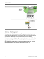
Figure 3: RS-485 bus serial wiring (KTD-405 keypad shown)
1. Keypad
2. I/O box
3. See section “RS-485 ports” on page 14
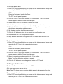
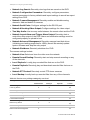
Use an RS-485 signal distributor for a star wiring configuration. See Figure 4
below.
Figure 4: Star wiring with RS-485 signal distributor
Correct
1. Keypad
2. I/O box
3. RS-485/KTD-83 distributor
4. See section “RS-485 ports” on page 14
Incorrect

1BChapter 2: Installation
14 TruVision DVR 60 User Manual
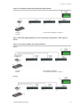
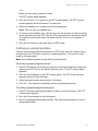
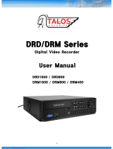
Use an RS-485/KTD-83 signal distributor to increase the maximum number of
devices on the bus as well as the total range. Each distributor output provides
another RS-485 bus, extending the output an additional 1200 m. Up to 31
TVR 60s can be connected to each output. See Figure 5 below.
Figure 5: Expanding the system with an RS-485 signal distributor
1. Keypad
2. I/O box
3. RS-485/KTD-83 distributor
4. See section “RS-485 ports” below
Caution: Most signal distributors are unidirectional. This means that the signal
only flows from the input towards the outputs. Consequently it is not possible to
connect several keypads.
See section “RS-485 ports” below to configure the RS-485 port communication
settings.
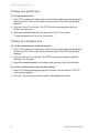
RS-485 ports
There are two RS-485 ports on the rear panel of the TVR 60. See Figure 6 on
page 15 for the serial pin outs.
• Dome RS-485:
Term G: Termination of RS-485 bus
G: Ground
A and B: Connect pan, tilt, zoom control of PTZ dome cameras. A = +, B = -
C and D: Not used
• Keyb: Connect the keypad.
Page is loading ...
Page is loading ...
Page is loading ...
Page is loading ...
Page is loading ...
Page is loading ...
Page is loading ...
Page is loading ...
Page is loading ...
Page is loading ...
Page is loading ...
Page is loading ...
Page is loading ...
Page is loading ...
Page is loading ...
Page is loading ...
Page is loading ...
Page is loading ...
Page is loading ...
Page is loading ...
Page is loading ...
Page is loading ...
Page is loading ...
Page is loading ...
Page is loading ...
Page is loading ...
Page is loading ...
Page is loading ...
Page is loading ...
Page is loading ...
Page is loading ...
Page is loading ...
Page is loading ...
Page is loading ...
Page is loading ...
Page is loading ...
Page is loading ...
Page is loading ...
Page is loading ...
Page is loading ...
Page is loading ...
Page is loading ...
Page is loading ...
Page is loading ...
Page is loading ...
Page is loading ...
Page is loading ...
Page is loading ...
Page is loading ...
Page is loading ...
Page is loading ...
Page is loading ...
Page is loading ...
Page is loading ...
Page is loading ...
Page is loading ...
Page is loading ...
Page is loading ...
Page is loading ...
Page is loading ...
Page is loading ...
Page is loading ...
Page is loading ...
Page is loading ...
Page is loading ...
Page is loading ...
Page is loading ...
Page is loading ...
Page is loading ...
Page is loading ...
Page is loading ...
Page is loading ...
Page is loading ...
Page is loading ...
Page is loading ...
Page is loading ...
Page is loading ...
Page is loading ...
Page is loading ...
Page is loading ...
Page is loading ...
Page is loading ...
Page is loading ...
Page is loading ...
Page is loading ...
Page is loading ...
Page is loading ...
Page is loading ...
Page is loading ...
Page is loading ...
Page is loading ...
Page is loading ...
Page is loading ...
Page is loading ...
Page is loading ...
Page is loading ...
Page is loading ...
Page is loading ...
Page is loading ...
Page is loading ...
Page is loading ...
Page is loading ...
Page is loading ...
Page is loading ...
Page is loading ...
Page is loading ...
Page is loading ...
Page is loading ...
Page is loading ...
Page is loading ...
Page is loading ...
Page is loading ...
Page is loading ...
Page is loading ...
Page is loading ...
Page is loading ...
Page is loading ...
Page is loading ...
Page is loading ...
Page is loading ...
Page is loading ...
Page is loading ...
Page is loading ...
Page is loading ...
Page is loading ...
Page is loading ...
Page is loading ...
Page is loading ...
Page is loading ...
Page is loading ...
Page is loading ...
Page is loading ...
Page is loading ...
Page is loading ...
Page is loading ...
Page is loading ...
Page is loading ...
Page is loading ...
Page is loading ...
Page is loading ...
Page is loading ...
Page is loading ...
Page is loading ...
Page is loading ...
-
 1
1
-
 2
2
-
 3
3
-
 4
4
-
 5
5
-
 6
6
-
 7
7
-
 8
8
-
 9
9
-
 10
10
-
 11
11
-
 12
12
-
 13
13
-
 14
14
-
 15
15
-
 16
16
-
 17
17
-
 18
18
-
 19
19
-
 20
20
-
 21
21
-
 22
22
-
 23
23
-
 24
24
-
 25
25
-
 26
26
-
 27
27
-
 28
28
-
 29
29
-
 30
30
-
 31
31
-
 32
32
-
 33
33
-
 34
34
-
 35
35
-
 36
36
-
 37
37
-
 38
38
-
 39
39
-
 40
40
-
 41
41
-
 42
42
-
 43
43
-
 44
44
-
 45
45
-
 46
46
-
 47
47
-
 48
48
-
 49
49
-
 50
50
-
 51
51
-
 52
52
-
 53
53
-
 54
54
-
 55
55
-
 56
56
-
 57
57
-
 58
58
-
 59
59
-
 60
60
-
 61
61
-
 62
62
-
 63
63
-
 64
64
-
 65
65
-
 66
66
-
 67
67
-
 68
68
-
 69
69
-
 70
70
-
 71
71
-
 72
72
-
 73
73
-
 74
74
-
 75
75
-
 76
76
-
 77
77
-
 78
78
-
 79
79
-
 80
80
-
 81
81
-
 82
82
-
 83
83
-
 84
84
-
 85
85
-
 86
86
-
 87
87
-
 88
88
-
 89
89
-
 90
90
-
 91
91
-
 92
92
-
 93
93
-
 94
94
-
 95
95
-
 96
96
-
 97
97
-
 98
98
-
 99
99
-
 100
100
-
 101
101
-
 102
102
-
 103
103
-
 104
104
-
 105
105
-
 106
106
-
 107
107
-
 108
108
-
 109
109
-
 110
110
-
 111
111
-
 112
112
-
 113
113
-
 114
114
-
 115
115
-
 116
116
-
 117
117
-
 118
118
-
 119
119
-
 120
120
-
 121
121
-
 122
122
-
 123
123
-
 124
124
-
 125
125
-
 126
126
-
 127
127
-
 128
128
-
 129
129
-
 130
130
-
 131
131
-
 132
132
-
 133
133
-
 134
134
-
 135
135
-
 136
136
-
 137
137
-
 138
138
-
 139
139
-
 140
140
-
 141
141
-
 142
142
-
 143
143
-
 144
144
-
 145
145
-
 146
146
-
 147
147
-
 148
148
-
 149
149
-
 150
150
-
 151
151
-
 152
152
-
 153
153
-
 154
154
-
 155
155
-
 156
156
-
 157
157
-
 158
158
-
 159
159
-
 160
160
-
 161
161
-
 162
162
-
 163
163
-
 164
164


Interlogix TVR-6016-500 User manual
- Category
- Digital Video Recorders (DVR)
- Type
- User manual
- This manual is also suitable for
Ask a question and I''ll find the answer in the document
Finding information in a document is now easier with AI
Related papers
-
Interlogix TruVision DVR 42 User manual
-
-
-
-
-
-
-
-
Interlogix TruVision TVD-M2225V-2-N User manual
-
Other documents
-
König SEC-DVR304-2 User manual
-
 Digital Watchdog DW-VMAX480 16 User manual
-
 Eclipse Security Nubix HD Series User manual
-
 Okina USA D08FF-16 User manual
-
 CiA TVV6204LUS User manual
-
 InterVision XPR-4004E User manual
-
 Safire DVR6104V-H User manual
-
 Talos Security DRD1600 User manual
-
Dahua NKB1000 Quick start guide
-
CONCORD QV5200CDK8848P-A Owner's manual


