Page is loading ...


ArtiLink600
Code Reader
USER MANUAL


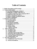
Content
Welcome .....................................................................................3
About ...........................................................................................3
Package List ...............................................................................3
Compatibility ..............................................................................3
Notice ..........................................................................................3
General Information of OBDII (On-Board Diagnostics II) .........4
Diagnostic Trouble Codes (DTCs) .............................................4
Product Descriptions .................................................................5
Operation Introduction ...............................................................6
Technical Specication ........................................................... 26
Warnings .................................................................................. 26
Cautions ................................................................................... 27
FAQ ........................................................................................... 27
Warranty .................................................................................. 28


EN
3
Welcome
About
Package List
Compatibility
Thank you for purchasing TOPDON OBD2 scan tool ArtiLink600. Please patiently
read and understand this User Manual before operating this product.
TOPDON ArtiLink600, the newest addition to the obd2 scanner series for 1996
and newer cars (OBDII & CAN), boasts a fully-featured list of tests and scans
ranging from ABS & SRS Diagnostic Capabilities, Oil/SAS/BMS Reset Services,
to comprehensive OBD2 tests, among others, making it highly-beneficial for
experienced DIYs, automotive mechanics, and garage owners.
TOPDON ArtiLink600 is compatible with the following protocols:
•ArtiLink600
•Diagnostic Cable
•Memory Card (Included in the Unit)
•Memory Card Adaptor
•USB Cable
•Quick Start Guide
•User Manual
•KWP2000
•ISO9141
•J1850 VPW
•J1850 PWM
•CAN (Controller Area Network)
•And more

4
General Information of OBDII (On-Board
Diagnostics II)
Diagnostic Trouble Codes (DTCs)
The OBDII system is designed to monitor emission control systems and key
engine components by performing either continuous or periodic tests of specic
components and vehicle conditions, which will offer three pieces of such valuable
information:
•Whether the Malfunction Indicator Light (MIL) is commanded “on” or “off”;
•Which, if any, Diagnostic Trouble Codes (DTCs) are stored;
•Readiness Monitor status.
Notice
ArtiLink600 may automatically reset while being disturbed by strong static
electricity. THIS IS A NORMAL REACTION.
This Product Manual is subject to change without written notice.
Read the instruction carefully and use the unit properly before operating. Fail
to do so may cause damage and/or personal injury, which will void the product
warranty.

EN
5
Product Descriptions
To connect to the diagnostic cable.
Show test results.
To connect the scanner to computer via USB cable for
upgrade, and printing.
To read or write the data/le stored in the TF card.
1
2
3
4TF Card Slot
DB-15 Diagnostic
Connector
LCD
USB Port
NameNO. Descriptions
1
2
13
3
4
5
6
7
8
910
11
12

6
•Quick access to I/M Readiness function.
•Delete the diagnostic record in the “Print” menu.
Provides detailed descriptions/tips for diagnostics.
Back to the previous page.
Move up for selection.
Move down for selection.
Move left for selection. Or skip to the previous
page when more than one page is displayed.
Move right for selection. Or skip to the next page when
more than one page is displayed.
To conrm the current operation.
Used to connect to the vehicle's DLC (Data Link
Connector)
8
9
10
11
12
13
I/M Shortcut
HELP Key
EXIT Key
Key
Key
Key
Key
OK Key
Diagnostic Cable
NameNO. Descriptions
▼
▼
▲
▲
•GREEN: No Fault Code.
•YELLOW: Pending Fault Code.
•RED: Permanent Fault Code.
Quick access to reading diagnostic trouble codes.
Quick access to erasing diagnostic trouble codes.
5
6
7
LED for Different
DTCs
Read DTC Shortcut
Erase DTC Shortcut

EN
7
Operation Introduction
1. Preparation & Connection
1.1 Turn the ignition off.
1.3 Plug the diagnostic cable into the vehicle’s DLC socket.
1.2 Locate the vehicle’s DLC socket.

8
*Note: Don’t connect or disconnect any test equipment with the ignition on or
engine running.
1.4 Turn the ignition on. The engine can be off or running.
1.5 ArtiLink600 will start initializing and enter the main menu interface.

EN
9
2. ABS/SRS Systems Diagnosing
This function is designed to diagnose the ABS (Anti-lock Brake System) and
SRS (Supplemental Restraint System) systems:
•Read version information.
•Read and clear fault code.
•Read data stream.
•Perform Active Test.
Refer to the flowchart illustrated as below to run the ABS/SRS diagnostics.
*Note:
1.Before diagnosing, please make sure the certain vehicle model has been
installed on the scanner.
2.The diagnostic menu may vary by the vehicle’s make, model and year.
Select “ABS/SRS”
Select Vehicle Manufacturer
Select Vehicle Model
Select Scan Mode
Automatic Select Manual Select
Select Test Function
Read Version
Information
Read Fault
Code
Clear Fault
Code
Read Data
Stream Active Test

10
3. Reset Services
TOPDON ArtiLink600 features 3 most-commonly used reset services for
effective daily vehicle maintenance.
This function enables you to reset the oil service lamp for the engine oil
life system, which calculates an optimal oil life change interval depending
on the vehicle driving conditions and weather events.
It needs to be performed in the following cases:
•If the service lamp is on, run car diagnostics rst for troubleshooting.
After that, reset the driving mileage or driving time, to turn off the
service lamp, and enable a new driving cycle.
•If the service lamp is not on, but you have changed the engine oil or
electric appliances that monitor oil life, you need to reset the service
lamp.
This function enables you to reset the steering angle.
It needs to be performed in the following cases:
•After replacing the steering angle position sensor.
•After replacing steering mechanical parts (such as steering gearbox,
steering column, end tie rod, steering knuckle)
•After performing four-wheel alignment, or recovering the car body.
This function enables you to perform a resetting operation on the
monitoring unit of the vehicle battery, in which the original low battery
fault information will be cleared and the battery matching will be done.
It needs to be performed in the following cases:
•The main battery is replaced.
•The battery monitoring sensor is replaced.
There are two methods to run the reset services:
Follow the automatic command from the scanner to complete the reset
procedures to the vehicle’s ECU.
The system will guide you to complete the reset procedures by following
on-screen prompts to select appropriate execution options, enter correct
data / values, and perform necessary actions.
Refer to the flowchart illustrated as below to run the reset procedures.
3.1 Oil Reset
3.2 Steering Angle Reset
3.3 Battery Maintenance System Reset
•Auto Reset
•Manual Reset

EN
11
Select “SERVICE”
Choose the Desired
Reset Function
Select the Desired
Car Brand
Select the Reset Method
Follow the On-Screen
Instructions to Proceed
*Note: The reset mode may vary by the vehicle’s make, model and year.
4. OBDII/EOBD Diagnosing
After the scanner is properly connected to the vehicle’s DLC, select [OBDII] in
the main menu and press [OK]. The scanner will start an automatic check of
the vehicle’s computer to determine which type of communication protocol
the vehicle is using, and then establish a communication link.
Then the screen will display the Monitor Status as follows:

12
This option identies which section of the emission control system has
malfunctioned.
Select [Read Codes] and press [OK]. The scanner will automatically read
the SAE-standard DTCs and the following screen will appear:
*Note: Never replace a part based only on the DTC denition. Always refer
to the vehicle’s service manual for detailed testing instructions.
If the code is dened by the vehicle’s manufacturer, the following screen
will appear:
4.1 Read Codes
Press [OK] to conrm. The following screen will appear:
DIAGNOSTIC MENU

EN
13
Press [OK] to enter:
Select the manufacturer. The result may be shown as follows:

14
This option erases the codes from the vehicle, after retrieving codes from
the vehicle and certain repairs have been carried out.
Select [Erase Codes] and press [OK], then follow the prompts on the screen
to nish the procedure.
The result may be shown as follows:
*Note: Be sure the vehicle’s ignition key is in the ON position with the
engine off.
4.2 Erase Codes
This option checks whether or not the various emissions-related systems
on the vehicle are operating properly, and are ready for Inspection and
Maintenance testing.
It can also be used to check the Monitor Run Status, and to conrm if the
repair of a car fault has been performed correctly.
Select [I/M Readiness] and press [OK].
The result may be shown as follows:
4.3 I/M Readiness
I/M Readiness
HTR

EN
15
*Explanation of terms:
•MIL - Malfunction Indicator Light
•IGN - The Ignition Method of the Vehicle
•DTC - Diagnostic Trouble Code
•PD DTC -Pending Diagnostic Trouble Code
•MIS - Misre Monitor
•FUE - Fuel System Monitor
•CCM - Comprehensive Components Monitor
•CAT - Catalyst Monitor
•HCAT - Heated Catalyst Monitor
•EVAP - Evaporative System Monitor
•AIR - Secondary Air Monitor
•O2S - O2 Sensors Monitor
•HTR - O2 Sensor Heater Monitor
•EGR - EGR System Monitor
This option retrieves and displays live data and parameters from the
vehicle’s ECU.
Select [Data Stream] and press [OK], then follow the prompts on the screen
to nish the procedure.
The result may be shown as follows:
4.4 Data Stream

16
This option takes the snapshot of the operating conditions when an
emission-related fault occurs.
Select [Freeze Frame] and press [OK].
The result may be shown as follows:
4.5 View Freeze Frame
*Note: When DTCs is erased, Freeze Data may or may not be stored in
vehicle memory, which depends on the vehicle’s make, model and year.
This option retrieves O2 sensor monitor test results of the most recently
completed tests from the vehicle’s on-board computer.
Select [O2 Sensor Test] and press [OK], then follow the prompts on the
screen to nish the procedure.
The result may be shown as follows:
4.6 O2 Sensor Test

EN
17
This option retrieves test results for emission-related powertrain
components and systems that are not continuously monitored. The tests
available are determined by the vehicle manufacturer.
Select [On-Board Monitoring] and press [OK], then follow the prompts on
the screen to nish the procedure.
The result may be shown as follows:
4.7 On-Board Monitor Test
This option initiates a leak test for the vehicle’s EVAP system.
Select [EVAP System (mode$8)] and press [OK].
If the vehicle supports mode$8, the result may be shown as follows:
4.8 EVAP System Test
/