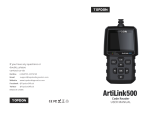
Topdon ArtiLink600 Code Reader User manual

Type
User manual

Topdon ArtiLink600 Code Reader offers you a wide range of diagnostic capabilities for your vehicle's engine, ABS, airbags, oil life, steering angle, and battery. Read and erase fault codes, view live data, perform active tests, and reset service lights - all with this one user-friendly scan tool.

Topdon ArtiLink600 Code Reader offers you a wide range of diagnostic capabilities for your vehicle's engine, ABS, airbags, oil life, steering angle, and battery. Read and erase fault codes, view live data, perform active tests, and reset service lights - all with this one user-friendly scan tool.

ArtiLink600
Code Reader
USER MANUAL
Hotline (+86)0755-23576169
Website www.topdon.com
Facebook @TopdonOcial
Twitter @TopdonOcial
MADE IN CHINA
If you have any questions or
doubts, please
contact us via
Content
Welcome .....................................................................................3
About ...........................................................................................3
Package List ...............................................................................3
Compatibility ..............................................................................3
Notice ..........................................................................................3
General Information of OBDII (On-Board Diagnostics II) .........4
Diagnostic Trouble Codes (DTCs) .............................................4
Product Descriptions .................................................................5
Operation Introduction ...............................................................6
Technical Specication ........................................................... 26
Warnings .................................................................................. 26
Cautions ................................................................................... 27
FAQ ........................................................................................... 27
EN
3
Welcome
About
Package List
Compatibility
Thank you for purchasing TOPDON OBD2 scan tool ArtiLink600. Please patiently
read and understand this User Manual before operating this product.
TOPDON ArtiLink600, the newest addition to the obd2 scanner series for 1996
and newer cars (OBDII & CAN), boasts a fully-featured list of tests and scans
ranging from ABS & SRS Diagnostic Capabilities, Oil/SAS/BMS Reset Services,
to comprehensive OBD2 tests, among others, making it highly-beneficial for
experienced DIYs, automotive mechanics, and garage owners.
TOPDON ArtiLink600 is compatible with the following protocols:
ArtiLink600
Diagnostic Cable
Memory Card (Included in the Unit)
Memory Card Adaptor
USB Cable
Quick Start Guide
User Manual
KWP2000
ISO9141
J1850 VPW
J1850 PWM
CAN (Controller Area Network)
And more
EN
4 5
General Information of OBDII (On-Board
Diagnostics II)
Diagnostic Trouble Codes (DTCs)
The OBDII system is designed to monitor emission control systems and key
engine components by performing either continuous or periodic tests of specic
components and vehicle conditions, which will offer three pieces of such valuable
information:
Whether the Malfunction Indicator Light (MIL) is commanded “on” or “off”;
Which, if any, Diagnostic Trouble Codes (DTCs) are stored;
Readiness Monitor status.
Product Descriptions
To connect to the diagnostic cable.
Show test results.
To connect the scanner to computer via USB cable for
upgrade, and printing.
To read or write the data/le stored in the TF card.
1
2
3
4TF Card Slot
DB-15 Diagnostic
Connector
LCD
USB Port
NameNO. Descriptions
1
2
3
4
5
6
7
8
910
11
13
12
Notice
ArtiLink600 may automatically reset while being disturbed by strong static
electricity. THIS IS A NORMAL REACTION.
This Product Manual is subject to change without written notice.
Read the instruction carefully and use the unit properly before operating. Fail
to do so may cause damage and/or personal injury, which will void the product
warranty.
EN
6 7
Quick access to I/M Readiness function.
Delete the diagnostic record in the “Print” menu.
Provides detailed descriptions/tips for diagnostics.
Back to the previous page.
Move up for selection.
Move down for selection.
Move left for selection. Or skip to the previous
page when more than one page is displayed.
Move right for selection. Or skip to the next page when
more than one page is displayed.
To conrm the current operation.
To connect to the vehicle’s DLC (Data Link Connector), with
LED illumination for the clear inspection in the dark area.
8
9
10
11
12
13
I/M Shortcut
HELP Key
EXIT Key
Key
Key
Key
Key
OK Key
Diagnostic Cable
with LED
NameNO. Descriptions Operation Introduction
1. Preparation & Connection
1.1 Turn the ignition off.
GREEN: No Fault Code.
YELLOW: Pending Fault Code.
RED: Permanent Fault Code.
Quick access to reading diagnostic trouble codes.
Quick access to erasing diagnostic trouble codes.
5
6
7
LED for Different
DTCs
Read DTC Shortcut
Erase DTC Shortcut
1.3 Plug the diagnostic cable into the vehicle’s DLC socket.
1.2 Locate the vehicle’s DLC socket.
EN
8 9
*Note: Don’t connect or disconnect any test equipment with the ignition on or
engine running.
2. ABS/SRS Systems Diagnosing
This function is designed to diagnose the ABS (Anti-lock Brake System) and
SRS (Supplemental Restraint System) systems:
Read version information.
Read and clear fault code.
Read data stream.
Perform Active Test.
Refer to the flowchart illustrated as below to run the ABS/SRS diagnostics.
*Note:
1.Before diagnosing, please make sure the certain vehicle model has been
installed on the scanner.
2.The diagnostic menu may vary by the vehicle’s make, model and year.
Select “ABS/SRS”
Select Vehicle Manufacturer
Select Vehicle Model
Select Scan Mode
Automatic Select Manual Select
Select Test Function
Read Version
Information
Read Fault
Code
Clear Fault
Code
Read Data
Stream Active Test
1.4 Turn the ignition on. The engine can be off or running.
1.5 ArtiLink600 will start initializing and enter the main menu interface.
EN
10 11
3. Reset Services
TOPDON ArtiLink600 features 3 most-commonly used reset services for
effective daily vehicle maintenance.
This function enables you to reset the oil service lamp for the engine oil
life system, which calculates an optimal oil life change interval depending
on the vehicle driving conditions and weather events.
It needs to be performed in the following cases:
If the service lamp is on, run car diagnostics rst for troubleshooting.
After that, reset the driving mileage or driving time, to turn off the
service lamp, and enable a new driving cycle.
If the service lamp is not on, but you have changed the engine oil or
electric appliances that monitor oil life, you need to reset the service
lamp.
This function enables you to reset the steering angle.
It needs to be performed in the following cases:
After replacing the steering angle position sensor.
After replacing steering mechanical parts (such as steering gearbox,
steering column, end tie rod, steering knuckle)
After performing four-wheel alignment, or recovering the car body.
This function enables you to perform a resetting operation on the
monitoring unit of the vehicle battery, in which the original low battery
fault information will be cleared and the battery matching will be done.
It needs to be performed in the following cases:
The main battery is replaced.
The battery monitoring sensor is replaced.
There are two methods to run the reset services:
Follow the automatic command from the scanner to complete the reset
procedures to the vehicle’s ECU.
The system will guide you to complete the reset procedures by following
on-screen prompts to select appropriate execution options, enter correct
data / values, and perform necessary actions.
Refer to the flowchart illustrated as below to run the reset procedures.
3.1 Oil Reset
3.2 Steering Angle Reset
3.3 Battery Maintenance System Reset
Auto Reset
Manual Reset
Select “SERVICE”
Choose the Desired
Reset Function
Select the Desired
Car Brand
Select the Reset Method
Follow the On-Screen
Instructions to Proceed
*Note: The reset mode may vary by the vehicle’s make, model and year.
4. OBDII/EOBD Diagnosing
After the scanner is properly connected to the vehicle’s DLC, select [OBDII] in
the main menu and press [OK]. The scanner will start an automatic check of
the vehicle’s computer to determine which type of communication protocol
the vehicle is using, and then establish a communication link.
Then the screen will display the Monitor Status as follows:
EN
12 13
This option identies which section of the emission control system has
malfunctioned.
Select [Read Codes] and press [OK]. The scanner will automatically read
the SAE-standard DTCs and the following screen will appear:
*Note: Never replace a part based only on the DTC denition. Always refer
to the vehicle’s service manual for detailed testing instructions.
If the code is dened by the vehicle’s manufacturer, the following screen
will appear:
4.1 Read Codes
Press [OK] to enter:
Select the manufacturer. The result may be shown as follows:
Press [OK] to conrm. The following screen will appear:
DIAGNOSTIC MENU
EN
14 15
This option erases the codes from the vehicle, after retrieving codes from
the vehicle and certain repairs have been carried out.
Select [Erase Codes] and press [OK], then follow the prompts on the screen
to nish the procedure.
The result may be shown as follows:
*Note: Be sure the vehicle’s ignition key is in the ON position with the
engine off.
4.2 Erase Codes
This option checks whether or not the various emissions-related systems
on the vehicle are operating properly, and are ready for Inspection and
Maintenance testing.
It can also be used to check the Monitor Run Status, and to conrm if the
repair of a car fault has been performed correctly.
Select [I/M Readiness] and press [OK].
*Explanation of terms:
MIL - Malfunction Indicator Light
IGN - The Ignition Method of the Vehicle
DTC - Diagnostic Trouble Code
PD DTC -Pending Diagnostic Trouble Code
MIS - Misre Monitor
FUE - Fuel System Monitor
CCM - Comprehensive Components Monitor
CAT - Catalyst Monitor
HCAT - Heated Catalyst Monitor
EVAP - Evaporative System Monitor
AIR - Secondary Air Monitor
O2S - O2 Sensors Monitor
HTR - O2 Sensor Heater Monitor
EGR - EGR System Monitor
The result may be shown as follows:
4.3 I/M Readiness
I/M Readiness
HTR
This option retrieves and displays live data and parameters from the
vehicle’s ECU.
Select [Data Stream] and press [OK], then follow the prompts on the screen
to nish the procedure.
The result may be shown as follows:
4.4 Data Stream
EN
16 17
This option takes the snapshot of the operating conditions when an
emission-related fault occurs.
Select [Freeze Frame] and press [OK].
The result may be shown as follows:
4.5 View Freeze Frame
*Note: When DTCs is erased, Freeze Data may or may not be stored in
vehicle memory, which depends on the vehicle’s make, model and year.
This option retrieves O2 sensor monitor test results of the most recently
completed tests from the vehicle’s on-board computer.
Select [O2 Sensor Test] and press [OK], then follow the prompts on the
screen to nish the procedure.
The result may be shown as follows:
4.6 O2 Sensor Test
This option retrieves test results for emission-related powertrain
components and systems that are not continuously monitored. The tests
available are determined by the vehicle manufacturer.
Select [On-Board Monitoring] and press [OK], then follow the prompts on
the screen to nish the procedure.
The result may be shown as follows:
4.7 On-Board Monitor Test
This option initiates a leak test for the vehicle’s EVAP system.
Select [EVAP System (mode$8)] and press [OK].
If the vehicle supports mode$8, the result may be shown as follows:
4.8 EVAP System Test
EN
18 19
The result may be shown as follows:
5. Review
This option is designed to review or delete the recorded DTC, Data Streams
and Freeze Frame, as following:
6. DTC Lookup
This function enables you to view the detailed denition of the retrieved DTC.
Select [LOOKUP] in the Main Menu and press [OK]. The following screen
will appear:
After you input the DTC, press [OK] to view its detailed denition.
You can press [HELP] to view the diagnostic tips/solution related with the DTC.
This option retrieves a list of information (provided by the vehicle
manufacturer) from the vehicle’s on-board computer.
This information may include:
VIN (Vehicle Identication Number).
CID (Calibration ID).
CVN (Calibration Verication Number).
Select [Vehicle Information] and press [OK].
4.9 Vehicle Info
EN
20 21
7. Print
This function is used to print the records saved in Read Codes or Data Stream.
Connect the scanner to the computer via the USB cable. The following screen
will appear:
Press [EXIT], and enter the main menu.
Run the Update Tool on your computer. The system will automatically detect
the Serial Number of the scanner.
Select [Print Manager].
The following screen will appear:
EN
22 23
Select [PRINT] in the main menu of the scanner. Select the data you want to
print and press [OK].
Select the le to be printed. Press [OK]. The selected le will be uploaded to
your computer and displayed on the print manager.
8. Help
This function enables you to view the scanner’s information and the
OBD introduction.
Select [HELP] in the Main menu and then press [OK]. The following screen
will appear:
*Explanation of terms:
DLC Location Information - Helps pinpoint the location of the vehicle’s DLC.
Abbreviation - Shows the full name and detailed explanation of the
automotive glossary abbreviations.
Tool Information - Shows the serial number and register code of
the scanner.
About OBD - Shows relevant introduction information about OBD.
Upgrade Information - Shows the website link to download the
update suite.
Modify the personal information.
Export the data, and save them into a .txt le on your computer.
Delete all the data in the text box.
Print all the data in the text box via a printer being connected to your
computer.
Quit the operation.
EN
24 25
9. Settings
Select [SETUP] in the main menu and press [OK]. The following screen
will appear:
*Explanation of terms:
Language - to set the user interface language.
Unit of Measure - to set a measurement unit.
Beeper - to set the buzzer On/Off.
Record Mode - to turn On/Off recording function.
10. Register & Update
A computer that can access the Internet is required.
Go to https://www.topdon.com/products/artilink600, click “DOWNLOADS”
of the page, and select “Update File”.
Download, decompress and install the TOPDON ArtiLink600 Update
software package on your computer (compatible with Windows XP, 7, 8 & 10).
After the update software package is installed, connect ArtiLink600 to the
computer via the USB cable.
Run the TOPDON Update Tool on your computer, the system will
automatically detect the Serial Number of the scanner.
Select Language, and click [Device Upgrade].
10.1 Register
The following screen will appear:
*Note: The serial number and the register code of the scanner are available in
“Help -> Tool Information” for manual input in case the scanner cannot detect
the data automatically.
Input the information required. Click [Submit] to nish the registration.
EN
26 27
Technical Specication
Display: 3.5”Color LCD with 320*480 Resolutions
Input Voltage Range: 9~18V
Working Temperature: 32 to 122 (0 to 50°C)
Storage Temperature: -4 to 158 (-20 to 70°C) @ RM60%
Dimensions: 6.07*3.43*1.22 inches (154.3*87*31 mm)
Weight: 14.64 oz (415g)
Warnings
Always perform automotive testing in a safe environment.
DO NOT smoke near the vehicle during testing.
DO NOT place the code reader near the engine or exhaust pipe to avoid
damage from high temperatures.
DO NOT wear loose clothing or jewelry when working on an engine.
DO NOT connect or disconnect any test equipment while the ignition is on or
the engine is running.
DO NOT disassemble the code reader.
Engine parts will become hot when the engine is running. To prevent severe
burns, avoid contact with hot engine parts.
When an engine is running, it produces carbon monoxide, a toxic and
poisonous gas. Operate the vehicle ONLY in a well-ventilated area.
Wear safety eye protection that meets ANSI standards.
Cautions
Please ensure that the vehicle battery is fully charged and the scanner is
rmly connected to the vehicle DLC to avoid erroneous data generated by the
scanner and diagnostic systems.
Please do not use the code reader during driving.
Keep clothing, hair, hands, tools, test equipment, etc. away from all moving
or hot engine parts.
Keep the scanner dry, clean, free from oil/water, or grease. Use a mild
detergent on a clean cloth to clean the outside of the scan tool, when
necessary.
Keep the scanner out of the reach of children.
FAQ
Q: System halts when reading the data stream. What is the reason?
A: It may be caused by a slackened connector. Please turn off the scanner, rmly
connect the connector, and switch it on again.
Q: How to deal with the flickering screen, or the damaged font while using
the scanner?
A: This bug can be xed by doing the following procedures:
1.Insert the memory card into the scanner, and then connect the scanner to the
PC via the USB cable.
2.The system will automatically upgrade the rmware and then reboot.
Q: Screen flashes at engine ignition start.
A: Caused by electromagnetic disturbing, and this is a normal phenomenon.
Q: There is no response when communicating with the on-board computer.
A: Please conrm the proper voltage of the power supply and check if the throttle
has been closed, the transmission is in the neutral position, or the water is in
proper temperature.
Q: Why are there so many fault codes?
A: Usually, it’s caused by a poor connection or fault circuit grounding.
Q: What to do if the scanner fails to boot up?
A: Please connect the scanner to a computer via the USB cable to x the rmware.
Q: Why the DTCs cannot be erased?
A: 1.Please conrm the malfunction related to DTCs has been properly xed.
2.Please switch the ignition OFF. Wait for 1~3 minutes, then start the vehicle.
Install the memory card into the supplied adaptor, and insert it into the
USB port of the computer.
Reopen the update tool.
Select the updates you desire, and then click [Download] to download the
update package into the memory card.
Insert the memory card with the downloaded update package into
ArtiLink600.
Power up ArtiLink600 via the USB cable.
ArtiLink600 will verify the update les in the memory card, and will
automatically start updating if a newer version is detected.
10.2 Update
28
FCC Statement:
This device complies with Part 15 of the FCC Rules. Operation is subject to the
following two conditions:
(1) This device may not cause harmful interference, and
(2) This device must accept any interference received, including
interference that may cause undesired operation.
After that, try to run “Read Codes” again. (Some DTCs can only be erased in
this way.)
  • Page 1 1
  • Page 2 2
  • Page 3 3
  • Page 4 4
  • Page 5 5
  • Page 6 6
  • Page 7 7
  • Page 8 8
  • Page 9 9
  • Page 10 10
  • Page 11 11
  • Page 12 12
  • Page 13 13
  • Page 14 14
  • Page 15 15
  • Page 16 16

Topdon ArtiLink600 Code Reader User manual

Type
User manual

Topdon ArtiLink600 Code Reader offers you a wide range of diagnostic capabilities for your vehicle's engine, ABS, airbags, oil life, steering angle, and battery. Read and erase fault codes, view live data, perform active tests, and reset service lights - all with this one user-friendly scan tool.

Ask a question and I''ll find the answer in the document

Finding information in a document is now easier with AI