Page is loading ...

Hotline (+86) 0755-23576169
Email [email protected]
Website www.topdondiagnostics.com
Facebook @TopdonOcial
Twitter @TopdonOcial
If you have any questions
or doubts, please
contact us via
PS
E
ArtiLink200
Code Reader
USER MANUAL

Welcome
About
Package List
Compatibility
General Information of OBDII
Features
Operation Introduction
Technical Specication
Warranty
Warnings
Cautions
FAQ
3
3
3
4
4
14
16
36
37
38
39
40
Content

EN
3
English
Welcome
Thank you for purchasing TOPDON ArtiLink200 code reader. Please take time
to read and understand this User Manual before operating this product.
About
ArtiLink200, featuring codes reading/clearing, the check engine light
turning off, I/M readiness status checking, freeze frame data viewing and
vehicle identication number retrieving, is truly the ultimate must-have
OBDII code reader in efciency and affordability for beginners looking for a
fast and accurate solution to Engine and AT systems’ fault codes.
Package List
1.TOPDON ArtiLink200 Code Reader 2.User Manual

EN
4
5
Compatibility
General Information of OBDII
Please be noted that ArtiLink200 works on most 1996 US-based, 2000
EU-based and newer vehicles that are equipped with 16-pin port and are
compliance with OBDII/CAN protocols.
1.On-Board Diagnostics (OBD) II
The rst generation of On-Board Diagnostics (called OBD I) was
developed by the California Air Resources Board (ARB) and implemented
in 1988 to monitor some of the emission control components on
vehicles. As technology evolved and the desire to improve the On-Board
Diagnostic system increased, a new generation of On-Board Diagnostic
system was developed. This second generation of On-Board Diagnostic
regulations is called “OBDII".
The OBDII system is designed to monitor emission control systems and
key engine components by performing either continuous or periodic
Whether the Malfunction Indicator Light (MIL) is commanded “ON”
or “OFF”;
Which, if any, Diagnostic Trouble Codes (DTCs) are stored;
Readiness Monitor status.
1)
2)
3)
2.Diagnostic Trouble Codes (DTCs)
OBDII Diagnostic Trouble Codes are codes that are stored by the on-
board computer diagnostic system in response to a problem found in the
vehicle. These codes identify a particular problem area and are intended
to provide you with a guide as to where a fault might be occurring
tests of specic components and vehicle conditions. When a problem is
detected, the OBDII system turns on a warning lamp (MIL) on the vehicle
instrument panel to alert the driver typically by the phrase of “Check
Engine” or “Service Engine Soon”. The system will also store important
information about the detected malfunction so that a technician can
accurately nd and x the problem. Here below follow three pieces of
such valuable information:

EN
6
7
3.Location of the Data Link Connector (DLC)
The DLC (Data Link Connector or Diagnostic Link Connector) is the
standardized 16-cavity connector where diagnostic code readers
interface with the vehicle's on-board computer. The DLC is usually
located like below:
within a vehicle. OBDII Diagnostic Trouble Codes consist of a ve-digit
alphanumeric code. The rst character, a letter, identies which control
system sets the code. The other four characters, all numbers, provide
additional information on where the DTC originated and the operating
conditions that caused it to set. Here below is an example to illustrate the
structure of the digits:
P0202
DTC Example
B=Body
C=Chassis
P=Powertrain
U=Network
Systems
Malfunctioning
Section of the Systems
Iden tifying specific
Generic(SAE):
P0, P2, P34-P39
B0, B3
C0, C3
U0, U3
CODE TYPE
Sub-s ystems
A
B
C
D

EN
8
9
4.OBDII Readiness Monitors
An important part of a vehicle’s OBDII system is the Readiness Monitors,
which are indicators used to nd out if all of the emissions components
have been evaluated by the OBDII system. They are running periodic
tests on specic systems and components to ensure that they are
performing within allowable limits.
Currently, there are eleven OBDII Readiness Monitors (or I/M Monitors)
dened by the U.S. Environmental Protection Agency (EPA). Not all
monitors are supported by all vehicles and the exact number of monitors
in any vehicle depends on the motor vehicle manufacturer’s emissions
control strategy.
Continuous Monitors -- Some of the vehicle components or systems
are continuously tested by the vehicle’s OBDII system, while others
are tested only under specic vehicle operating conditions. The
continuously monitored components listed below are always ready:
Non-Continuous Monitors -- Unlike the continuous monitors, many
emissions and engine system components require the vehicle to be
operated under specic conditions before the monitor is ready. These
monitors are termed non-continuous monitors and are listed below:
Comprehensive Components (CCM)
Misre
Fuel System
EGR System
O2 Sensors
Catalyst
Evaporative System
O2 Sensor Heater
Secondary air
Heated Catalyst
A/C system
Once the vehicle is running, the OBDII system is continuously checking
the above components, monitoring key engine sensors, watching for
engine misre, and monitoring fuel demands.
3)
1)
1) 5)
2)
2) 6)
3) 7)
4) 8)

EN
11
5.OBDII Monitor Readiness Status
6.OBDII Denitions
OBDII systems must indicate whether or not the vehicle’s PCM’s monitor
system has completed testing on each component. Components that
have been tested will be reported as “Ready”, or “Complete”, meaning
they have been tested by the OBDII system. The purpose of recording
readiness status is to allow inspectors to determine if the vehicle’s
OBDII system has tested all the components and/or systems.
The powertrain control module (PCM) sets a monitor to “Ready” or
“Complete” after an appropriate drive cycle has been performed. The
drive cycle that enables a monitor and sets readiness codes to “Ready”
varies for each individual monitor. Once a monitor is set as “Ready” or
“Complete”, it will remain in this state. A number of factors, including
erasing of diagnostic trouble codes (DTCs) with a code reader or a
disconnected battery, can result in Readiness Monitors being set to “Not
Ready”. Since the three continuous monitors are constantly evaluating,
they will be reported as “Ready” all of the time. If testing of particular
supported non-continuous monitor has not been completed, the monitor
status will be reported as “Not Complete” or “Not Ready.”
Powertrain Control Module (PCM) -- OBDII terminology for the on-board
computer that controls engine and drive train.
Malfunction Indicator Light (MIL) -- Malfunction Indicator Light
(Service Engine Soon, Check Engine) is a term used for the light on the
instrument panel. It is to alert the driver and/or the repair technician
that there is a problem with one or more of vehicle's systems and may
cause emissions to exceed federal standards. If the MIL illuminates
with a steady light, it indicates that a problem has been detected and
the vehicle should be serviced as soon as possible. Under certain
conditions, the dashboard light will blink or flash. This indicates a severe
In order for the OBD monitor system to become ready, the vehicle
should be driven under a variety of normal operating conditions. These
operating conditions may include a mix of highway driving and stop and
go, city type driving, and at least one overnight off period. For specic
information on getting your vehicle’s OBD monitor system ready, please
consult your User Manual.

EN
13
problem and flashing is intended to discourage vehicle operation. The
vehicle onboard diagnostic system cannot turn the MIL off until the
necessary repairs are completed or the condition no longer exists.
DTC -- Diagnostic Trouble Codes (DTC) that identify which section of the
emission control system has malfunctioned.
Enabling Criteria -- Also termed Enabling Conditions. They are the
vehicle-specic events or conditions that must occur within the engine
before the various monitors will set, or run. Some monitors require
the vehicle to follow a prescribed “Drive Cycle” routine as part of the
enabling criteria. Drive cycles vary among vehicles and for each monitor
in any particular vehicle.
OBDII Drive Cycle -- A specic mode of vehicle operation that provides
conditions required to set all the readiness monitors applicable to the
vehicle to the “Ready” condition. The purpose of completing an OBDII
drive cycle is to force the vehicle to run its onboard diagnostics. Some
form of a drive cycle needs to be performed after DTCs have been erased
from the PCM’s memory or after the battery has been disconnected.
Running through a vehicle’s complete drive cycle will “Set” the readiness
monitors so that future faults can be detected. Drive cycles vary
depending on the vehicle and the monitor that needs to be reset. For
vehicle specic drive cycle, consult the User Manual.
Freeze Frame Data -- When an emissions related fault occurs, the OBDII
system not only sets a code but also records the vehicle operating
parameters to help in identifying the problem. This set of values is
referred to as Freeze Frame Data and may include important engine
parameters such as engine RPM, vehicle speed, air flow, engine load,
fuel pressure, fuel trim value, engine coolant temperature, ignition timing
advance, or closed loop status.

EN
14
15
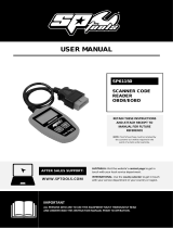
Features
Connects the code reader to the vehicle’s
Data Link Connector (DLC)
ENTER
EXIT
16-pin Connector
Buttons
Operation
▼
▲
Page up, or increase the battery rating values
Page down, or decrease the battery rating values
Conrm; Enter and proceed
Cancel; Return to the previous page

EN
16
17
Operation Introduction
Connect ArtiLink200 with your vehicle.
NOTE: Don’t connect or disconnect any test equipment with ignition on or
engine running.
Turn the ignition off.
Locate the vehicle’s 16-pin Data Link Connector (DLC).
Plug into the OBDII cable to the vehicle’s DLC.
Turn the ignition on. Engine can be off or running.
Press “ENTER” button to enter “Diagnostic Menu”. A sequence of
messages displaying the OBDII protocols will be observed on the
display until the vehicle protocol is detected.
1)
2)
3)
4)
5)
1.Setup
The code reader allows you to make the following adjustments and
settings:
Language: Selects desired language.
Unit of measure: Sets the unit of measure to English or Metric.
Contrast adjustment: Adjusts the contrast of the LCD display.
1)
2)
3)

EN
18
19
2.Reading Codes
On Main Menu, press and hold the “ ” or “ ” button to select the
“Read Codes”, then press “ENTER” to continue.
If more than one module is detected, you will be prompted to select a
module before test. Press and hold the “ ” or “ ” button to select
a module.
1)
2)
▼▲
▼▲
View DTCs and their denitions on screen.3)

EN
20
21
If more than one DTC is found, press and hold the “ ” or “ ” until all
the codes have been shown up.
If no codes are detected, a “No codes are stored in the module!”
message displays on the screen.
If retrieved DTCs contain any manufacturer specic or enhanced
codes, the display indicates “Manufacturer control”.
NOTE: The control module number, sequence of the DTCs, total number
of codes detected and type of codes (Generic or Manufacturer specic,
Stored or Pending codes) will be observed on the upper right hand corner
of the display.
NOTE: The control module number, sequence of the DTCs, total number
of codes detected and type of codes (Generic or Manufacturer specic,
Stored or Pending codes) will be observed on the upper right hand
corner of the display.
4)
Press and hold the “EXIT” to return.5)
▼▲
3.Erasing Codes
If you decide to erase the DTCs, press and hold the “ ” or “ ” to
select “Erase Codes” and press “ENTER” to conrm.
1)
▼
▲

EN
22
23
4.Viewing Freeze Frame Data
Press and hold the “ ” or “ ” to select “View Freeze Frame” on
“Diagnostic Menu” and press “ENTER” to continue.
If more than one module is detected, you will be prompted to select a
module before test. Press and hold the “ ” or “ ” button to select
a module.
1)
2)
Choose “YES” to conrm erasing.
Wait a few seconds or press any key to return to “Diagnostic Menu”.
If you want to proceed with erasing the codes, press “ENTER” button
to erase.
If the codes are cleared successfully, an “Erase Done!” message will
display.
If the codes are not cleared, an “Erase Failure. Turn Key on with Engine
off!” message will display.
2)
4)
3)
▼
▼
▲
▲

EN
24
25
Wait a few seconds while the code reader validates the PID MAP.
If the retrieved information covers more than one screen, press and
hold the “ ” or “ ” until all data have been shown up.
3)
4)
Press and hold the “EXIT” to return.5)
▼▲

EN
26
27
completed its diagnostic testing.
“N/A” -- The monitor is not supported on that vehicle.
If more than one module is detected, you will be prompted to select a
module before test. Press and hold the “ ” or “ ” button to select
a module.
2)
Press and hold the “ ” or “ ” to select “I/M Readiness” on
“Diagnostic Menu” and press “ENTER” to continue.
1)
▼
▲
▼
▲
5.Retrieving I/M Readiness Status
I/M Readiness function is used to check the operations of the Emission
System on OBDII compliant vehicles.
Some latest vehicle models may support two types of I/M Readiness
tests:
A.Since DTCs Cleared - indicates status of the monitors since the DTCs
are erased.
B.This Drive Cycle - indicates status of monitors since the beginning of
the current drive cycle.
NOTE: An I/M Readiness Status result of “NO” does not necessarily
indicate that the vehicle being tested will fail the state I/M inspection.
For some states, one or more such monitors may be allowed to be “Not
Ready” to pass the emissions inspection.
“OK” -- Indicates that a particular monitor being checked has completed
its diagnostic testing.
“INC” -- Indicates that a particular monitor being checked has not

EN
28
29
If the vehicle supports both types of tests, then both types shows on
the screen for selection.
4)
Press and hold the “ ” or “ ” to view the status of the MIL light (“ON”
or “OFF") and the following monitors:
Misre monitor -- Misre Monitor
Fuel System Mon -- Fuel System Monitor
Comp. Component -- Comprehensive Components Monitor
EGR -- EGR System Monitor
5)
▼
▲
Wait a few seconds while the code reader validates the PID MAP.3)

EN
30
31
If the vehicle supports readiness test of “This Drive Cycle”, a screen of
the following will be displayed:
6)
Press and hold the “EXIT” to return.7)
Oxygen Sens Mon -- O2 Sensors Monitor
Catalyst Mon -- Catalyst Monitor
EVAP System Mon -- Evaporative System Monitor
Oxygen Sens htr --O2 Sensor Heater Monitor
Sec Air System -- Secondary Air Monitor
Htd Catalyst -- Heated Catalyst Monitor
A/C Refrig Mon -- A/C System Monitor

EN
32
33
6.Viewing Vehicle Information
The Vehicle Info. function enables retrieval of the Vehicle Identication
No. (VIN), Calibration ID(s), Calibration Verication Nos. (CVNs) and In-
use Performance Tracking on 2000 and newer vehicles that support
Mode 9.
Press and hold the “ ” or “ ” to select “Vehicle Info” on “Diagnostic
Menu” and press “ENTER” to continue.
1)
▼▲
Wait a few seconds or press “ENTER” button to continue.2)
Wait a few seconds while the code reader reads vehicle information.3)

EN
34
35
From “Vehicle Info” menu, press and hold the “ ” or “ " to select an
available item to view and press “ENTER”.
4)
▼
▲
View retrieved vehicle information on the screen.5)
Press and hold the “EXIT” to return.6)
7.Exiting OBDII Test
Press and hold “EXIT” button to exit OBDII test, a warning message
comes up asking your conrmation.

EN
36
37
Technical Specication
Display: Backlight, 128
*
64 pixel display
Operating Voltage: 9~16V
Operating Current: 40~50mA
Energy Consumption: 0.6W
Power: 8 to 18 volts supplied by car battery
Supported Protocols: K Line, L Line, Double CAN, J1850 PWM, J1850 VPW
Communication Protocol
Main Chip Model: Binding chip
Interface Type: OBDII 16-pin Standard Interface
Product Material: ABS plastic, rubber keys
Product Weight: 202g (0.45lb)
Warranty
TOPDON One Year Limited Warranty
The TOPDON Company warrants to its original purchaser that TOPDON
products will be free from defects in material and workmanship for 12
months from the date of purchase (Warranty Period). For the defects
reported during the Warranty Period, TOPDON will, according to the
technical support analysis and conrmation, either repair or replace the
defective part or product.
This limited warranty is void under the following conditions:
Misused, disassembled, altered or repaired by a non-TOPDON technical
repair specialist.
Careless handling and violation of operation.
/