Page is loading ...

i
Trademarks
Autel
®
, MaxiSys
®
, MaxiDAS
®
, MaxiScan
®
, MaxiCheck
®
, MaxiRecorder
®
,
and MaxiCheck
®
are trademarks of Autel Intelligent Technology Corp., Ltd.,
registered in China, the United States and other countries. All other marks
are trademarks or registered trademarks of their respective holders.
Copyright Information
No part of this manual may be reproduced, stored in a retrieval system or
transmitted, in any form or by any means, electronic, mechanical,
photocopying, recording, or otherwise without the prior written permission of
Autel.
Disclaimer of Warranties and Limitation of Liabilities
All information, specifications and illustrations in this manual are based on
the latest information available at the time of printing.
Autel reserves the right to make changes at any time without notice. While
information of this manual has been carefully checked for accuracy, no
guarantee is given for the completeness and correctness of the contents,
including but not limited to the product specifications, functions, and
illustrations.
Autel will not be liable for any direct, special, incidental, indirect damages or
any economic consequential damages (including the loss of profits).
IMPORTANT
Before operating or maintaining this unit, please read this manual carefully,
paying extra attention to the safety warnings and precautions.
For Services and Support
pro.autel.com
www.autel.com
1-855-288-3587/1-855-AUTELUS (North America)
0086-755-86147779 (China)
For technical assistance in all other markets, please contact your local
selling agent.

ii
Safety Information
For your own safety and the safety of others, and to prevent damage to the
device and vehicles upon which it is used, it is important that the safety
instructions presented throughout this manual be read and understood by all
persons operating or coming into contact with the device.
There are various procedures, techniques, tools, and parts for servicing
vehicles, as well as in the skill of the person doing the work. Because of the
vast number of test applications and variations in the products that can be
tested with this equipment, we cannot possibly anticipate or provide advice
or safety messages to cover every circumstance. It is the automotive
technician’s responsibility to be knowledgeable of the system being tested. It
is crucial to use proper service methods and test procedures. It is essential
to perform tests in an appropriate and acceptable manner that does not
endanger your safety, the safety of others in the work area, the device being
used, or the vehicle being tested.
Before using the device, always refer to and follow the safety messages and
applicable test procedures provided by the manufacturer of the vehicle or
equipment being tested. Use the device only as described in this manual.
Read, understand, and follow all safety messages and instructions in this
manual.
Safety Messages
Safety messages are provided to help prevent personal injury and
equipment damage. All safety messages are introduced by a signal word
indicating the hazard level.
DANGER
Indicates an imminently hazardous situation which, if not avoided, will result
in death or serious injury to the operator or to bystanders.
WARNING
Indicates a potentially hazardous situation which, if not avoided, could result
in death or serious injury to the operator or to bystanders.

iii
Safety Instructions
The safety messages herein cover situations Autel is aware of. Autel cannot
know, evaluate or advise you as to all of the possible hazards. You must be
certain that any condition or service procedure encountered does not
jeopardize your personal safety.
DANGER
When an engine is operating, keep the service area WELL VENTILATED or
attach a building exhaust removal system to the engine exhaust system.
Engines produce carbon monoxide, an odorless, poisonous gas that causes
slower reaction time and can lead to serious personal injury or loss of life.
SAFETY WARNINGS
Always perform automotive testing in a safe environment.
Wear safety eye protection that meets ANSI standards.
Keep clothing, hair, hands, tools, test equipment, etc. away from all
moving or hot engine parts.
Operate the vehicle in a well-ventilated work area, for exhaust gases
are poisonous.
Put the transmission in PARK (for automatic transmission) or NEUTRAL
(for manual transmission) and make sure the parking brake is engaged.
Put blocks in front of the drive wheels and never leave the vehicle
unattended while testing.
Be extra cautious when working around the ignition coil, distributor cap,
ignition wires and spark plugs. These components create hazardous
voltages when the engine is running.
Keep a fire extinguisher suitable for gasoline, chemical, and electrical
fires nearby.
Do not connect or disconnect any test equipment while the ignition is on
or the engine is running.
Keep the test equipment dry, clean, free from oil, water or grease. Use a
mild detergent on a clean cloth to clean the outside of the equipment as
necessary.
Do not drive the vehicle and operate the test equipment at the same
time. Any distraction may cause an accident.
Refer to the service manual for the vehicle being serviced and adhere to
all diagnostic procedures and precautions. Failure to do so may result in

iv
personal injury or damage to the test equipment.
To avoid damaging the test equipment or generating false data, make
sure the vehicle battery is fully charged and the connection to the
vehicle DLC is clean and secure.
Do not place the test equipment on the distributor of the vehicle. Strong
electro-magnetic interference can damage the equipment.

v
CONTENTS
USING THIS MANUAL ........................................................................... 1
CONVENTIONS ........................................................................................... 1
USING THE SCAN TOOL ....................................................................... 3
TOOL DESCRIPTION .................................................................................... 3
SPECIFICATIONS ........................................................................................ 4
ACCESSORIES INCLUDED ............................................................................ 5
KEYPAD .................................................................................................... 5
POWER ..................................................................................................... 5
VEHICLE COVERAGE ................................................................................... 6
PRODUCT TROUBLESHOOTING ..................................................................... 6
OBD II DIAGNOSTICS ........................................................................... 8
READ CODES ........................................................................................... 10
ERASE CODES ......................................................................................... 11
LIVE DATA ............................................................................................... 12
VIEW FREEZE FRAME DATA....................................................................... 21
RETRIEVE I/M READINESS STATUS ............................................................ 22
O2 MONITOR TEST .................................................................................. 24
ON-BOARD MONITOR TEST ....................................................................... 26
COMPONENT TEST ................................................................................... 28
VIEW VEHICLE INFORMATION ..................................................................... 29
MODULES PRESENT ................................................................................. 31
CODE BREAKER ....................................................................................... 31
ABS ....................................................................................................... 33
READ CODES ........................................................................................... 33
ERASE CODES ......................................................................................... 34

vi
SRS ...................................................................................................... 36
READ CODES ........................................................................................... 36
ERASE CODES ......................................................................................... 36
DTC LOOKUP....................................................................................... 38
PLAYBACK DATA ................................................................................ 40
REVIEW DATA .......................................................................................... 40
DELETE DATA .......................................................................................... 41
PRINT DATA ............................................................................................ 41
SYSTEM SETUP .................................................................................. 44
LANGUAGE .............................................................................................. 44
UNIT OF MEASURE ................................................................................... 45
KEY BEEP SET ......................................................................................... 46
ABOUT .................................................................................................... 46
TOOL SELF-TEST...................................................................................... 47
UPDATE MODE ........................................................................................ 48
VEHICLE INFO SHOW SET ......................................................................... 51
COMPLIANCE INFORMATION ............................................................ 52
WARRANTY AND SERVICE ............................................................... 54
LIMITED ONE YEAR WARRANTY ................................................................. 54
SERVICE PROCEDURES ............................................................................ 54

1
Using This Manual
This manual contains device usage instructions.
Some illustrations shown in this manual may contain modules and optional
equipment that are not included in your system. Contact your sales
representative for availability of other modules and optional tools or
accessories.
Conventions
The following conventions are used.
Bold Text
Bold text is used to highlight selectable items such as buttons and menu
options.
Example:
Tap OK.
Notes and Important Messages
Notes
A NOTE provides helpful information such as additional explanations, tips,
and comments.
Example:
NOTE
New batteries reach full capacity after approximately 3 to 5 charging and
discharging cycles.
Important
IMPORTANT indicates a situation which, if not avoided, may result in
damage to the test equipment or vehicle.
Example:

2
IMPORTANT
Keep the cable away from heat, oil, sharp edges and moving parts. Replace
damaged cables immediately.
Hyperlink
Hyperlinks, or links, that take you to other related articles, procedures, and
illustrations are available in electronic documents. Blue italic text indicates a
selectable hyperlink and blue underlined text indicates a website link or an
email address link.
Illustrations
Illustrations used in this manual are samples, the actual testing screen may
vary by test vehicle. Observe the menu titles and on-screen instructions to
make correct option selection.

3
Using the Scan Tool
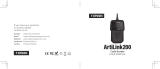
Tool Description
1) LCD DISPLAY –displays menus and test results.
2) FUNCTION BUTTONS – corresponds with “buttons” on screen for
executing commands.
3) HELP BUTTON – provides help information and Code Breaker
function.
4) ESC BUTTON – cancels a selection (or an action) from a menu or
returns to the previous screen.
5) LEFT SCROLL BUTTON – when look up DTC definitions, moves
to previous character and views additional information on previous
screens if DTC definition covers more than one screen; views previous
screen or previous frames of recorded data. It is also used to view
previous trouble code when viewing DTCs.
6) UP SCROLL BUTTON – moves up through menu and submenu
items in menu mode. When more than one screen of data is retrieved,
Figure 2-1 Scan Tool View

4
moves up through the current screen to the previous screens for
additional data. When looking up DTC, it is used to change value of
selected character.
7) RIGHT SCROLL BUTTON – When look up DTC definitions, moves
to next character and view additional information on next screens if DTC
definition covers more than one screen; views next screen or next
frames of recorded data. It is also used to view next trouble code when
viewing DTCs.
8) OK BUTTON – confirms a selection (or action) from a menu.
9) DOWN SCROLL BUTTON – moves down through menu and
submenu items in menu mode. When more than one screen of data is
retrieved, moves down through the current screen to next screens for
additional data. When looking up DTC, it is used to change value of
selected character.
10) OBD II CONNECTOR – connects the scan tool to the vehicle’s Data
Link Connector (DLC).
11) USB CONNECTOR – connects the scan tool to the PC for printing and
upgrading.
Specifications
Table 2-1 Specifications
Item
Description
Display
2.8-inch LCD (320 x 240 dpi)
Connectivity
USB mini 2.0
OBD II DB15
Operating Temp.
-10°C to 60°C (14°F to 140°F)
Storage Temp.
-20°C to 70°C (-4°F to 158°F)
External Power
8.0 to 18.0 V power provided via vehicle battery
Dimensions
(LxWxH)
182.8 mm (7.2”) x 90.9 mm (3.6”) x 33.2 mm
(1.3”)
Net Weight
237.9 g (0.524 lb.)

5
Accessories Included
1) OBDII Cable – provides power to tool and communicates between tool
and vehicle.
2) USB Cable – used to upgrade the scan tool and to print retrieved data.
3) User Manual – instructions on tool operations.
4) Quick Guide – instructions on device connection and tool registration
and update.
Keypad
No solvents such as alcohol are allowed to clean the keypad or display. Use
a mild nonabrasive detergent and a soft cotton cloth. Do not soak the
keypad as it is not waterproof.
Power
The scan tool is powered via the vehicle Data Link Connector (DLC). Follow
the steps below to turn on the scan tool:
1) Connect the OBD II Cable to the scan tool.
2) Find DLC on the vehicle.
A plastic DLC cover may be found for some vehicles and you need
to remove it before plugging the OBDII cable.
3) Plug OBD II cable to the vehicle’s DLC.
4) The scan tool will power up and the Main Screen will appear.
Figure 2-2 Sample Main Screen

6
Vehicle Coverage
The AutoLink
AL609P OBDII Scanner is specially designed to work with all
OBD II compliant vehicles, including those equipped with next-generation
protocol -- Control Area Network (CAN). It is required by EPA that all 1996
and newer vehicles (cars and light trucks) sold in the United States must be
OBD II compliant and this includes all Domestic, Asian and European
vehicles.
A small number of 1994 and 1995 model year gasoline vehicles are OBD II
compliant. To verify if a 1994 or 1995 vehicle is OBD II compliant, check the
Vehicle Emissions Control Information (VECI) Label which is located under
the hood or by the radiator of most vehicles. If the vehicle is OBD II
compliant, the label will designate “OBD II Certified”. Additionally,
Government regulations mandate that all OBD II compliant vehicles must
have a “common” sixteen-pin Data Link Connector (DLC).
For your vehicle to be OBD II compliant it must have a 16-pin DLC (Data
Link Connector) under the dash and the Vehicle Emission Control
Information Label must state that the vehicle is OBD II compliant.
In addition to OBD II diagnosis, the AL609P scan tool also reads and
erases codes for ABS and SRS, dealing with more than 50 US, Asian and
European vehicles, including Acura, Audi, Bentley, Benz, BMW, Bugatti,
Chrysler, Ford, EU Ford, GM, Honda, Hyundai, Infiniti, Isuzu, Jaguar, Kia,
Land Rover, Lexus, Maybach, Mazda, Mini, Mitsubishi, Nissan, Opel,
Porsche, Saab, Scion, Seat, Skoda, Smart, Sprinter, Suzuki, Toyota,
Vauxhall, Volvo, VW, Renault, Peugeot, Lancia, Fiat, Dacia, Citroen, Alfa,
Abarth.
More vehicle supports will come out with new updates released.
Product Troubleshooting
This part describes problems that you may encounter while using the scan
tool.
Vehicle Linking Error
A communication error occurs if the scan tool fails to communicate with the
vehicle’s ECU (Engine Control Unit). You need to do the following to check
up:

7
Verify that the ignition is ON.
Check if the scan tool’s OBD II connector is securely
connected to the vehicle’s DLC.
Verify that the vehicle is OBDII compliant.
Turn the ignition off and wait for about 10 seconds. Turn the ignition
back to on and continue the testing.
Verify the control module is not defective.
Operating Error
If the scan tool freezes, then an exception occurs or the vehicle’s ECU
(Engine Control Unit) is too slow to respond to requests. You need to do the
following to reset the tool:
Reset the scan tool.
Turn the ignition off and wait for about 10 seconds. Turn the ignition
back to on and continue the testing.
Scan tool doesn’t power up
If the scan tool won’t power up or operates incorrectly in any other way, you
need to do the following to check up:
Check if the scan tool’s OBD II connector is securely connected to the
vehicle’s DLC;
Check if the DLC pins are bent or broken. Clean the DLC pins if
necessary.
Check vehicle battery to make sure it is still good with at least 8.0 volts.
NOTE
Avoid electrostatic interference during operation. If a failure occurs due to
electrostatic interference, Please try to operate again.

8
OBD II Diagnostics
When more than one vehicle control module is detected by the scan tool,
you will be prompted to select the module where the data may be retrieved.
The most often to be selected are the Power train Control Module [PCM] and
Transmission Control Module [TCM].
CAUTION: Don’t connect or disconnect any test equipment with ignition on
or engine running.
1) Turn the ignition off.
2) Locate the vehicle’s 16-pin Data Link Connector (DLC).
3) Plug the scan tool cable connector into the vehicle’s DLC.
4) Turn the ignition on. Engine can be off or running.
5) Turn on the scan tool. Use the UP/DOWN scroll button to select
OBDII/EOBD from the Main Screen.
6) Press the OK button to wait for the Menu to appear. With the embedded
AutoVIN technology in the tool, a sequence of messages displaying the
OBDII protocols will be observed on the display until the test vehicle’s
protocol is detected. The test vehicle information will display as below
once it is done. Press OK to continue.
Figure 3-1 Sample Vehicle Info Screen
If the scan tool fails to communicate with the vehicle’s ECU (Engine
Control Unit) more than three times, a “LINKING ERROR!” message
shows up on the display.
Verify that the ignition is ON;
Check if the scan tool’s OBD II connector is securely connected to
the vehicle’s DLC;

9
Verify that the vehicle is OBD II compliant;
Turn the ignition off and wait for about 10 seconds. Turn the ignition
back to on and repeat the procedure from step 5.
If the “LINKING ERROR” message does not go away, then there might
be problems for the scan tool to communicate with the vehicle. Contact
your local distributor or the manufacturer’s customer service
department for assistance.
7) View a summary of system status (MIL status, DTC counts, Monitor
status) on screen. Wait a few seconds or press any key to continue.
Figure 3-2 Sample System Status Screen
If more than one module is detected, you will be prompted to select
a module before testing.
Use the UP/DOWN scroll button to select a module and press the
OK button.
8) Then you will be prompted to erase previously stored data.
Review previously stored data thoroughly before erasing.
Figure 3-3 Sample Erase Previous Data Screen
If no data is stored in the scan tool, the above prompt will not show
up.

10
9) If you wish to erase the data, press the OK button; if you do not want to
erase the data, press ESC to exit or use LEFT/RIGHT button to select
NO and press OK for Diagnostic Menu to come up.
Read Codes
Read Codes can be done with the key on engine off (KOEO) or with the
key on engine running (KOER).
Stored Codes are also known as “hard codes”, which are fault codes, or
trouble codes that have been stored in the vehicle computer memory
because the faults have reoccurred for more than a specified amount of
key-cycles. These codes will cause the control module to illuminate the
malfunction indicator light (MIL) when emission-related fault occurs.
Pending Codes are also referred to as “maturing codes” or “continuous
monitor codes”. They indicate problems that the control module has
detected during the current or last driving cycle but are not considered
serious yet. Pending Codes will not turn on the malfunction indicator
light (MIL). If the fault does not occur within a certain number of
warm-up cycles, the code clears from memory.
Permanent Codes are DTCs that are "confirmed" and are retained in
the non-volatile memory of the computer until the appropriate monitor
for each DTC has determined that the malfunction is no longer present
and is not commanding the MIL on. Permanent DTC shall be stored in
non-volatile memory and may not be erased by any diagnostic services
or by disconnecting power to ECU.
1) Use UP/DOWN scroll button to select Read Codes from Diagnostic
Menu and press OK button.
Figure 3-4 Sample Diagnostic Menu
2) Use the UP/DOWN scroll button to select OBDII Codes or Enhanced
Codes from the Read Codes menu and press the OK button.

11
Figure 3-5 Sample Read Codes Screen
The OBD Codes reads pending codes, stored codes, and
permanent codes. The Enhanced Codes reads DTCs from engine
and transmission systems of GM, Chrysler, and Ford vehicles.
If there is not any Diagnostic Trouble Code, the display indicates
“No (pending) codes are stored in the module!” Wait a few
seconds or press any key to return to previous screen.
NOTE
Permanent Codes function is available for merely vehicles supporting the
CAN protocols.
3) View DTCs and their definitions on screen.
Figure 3-6 Sample DTC Screen
4) If more than one DTC is found, use the LEFT/RIGHT scroll button to
check all the codes.
If retrieved DTCs contain any manufacturer specific or enhanced
codes, the AutoVIN technology adopted by this tool will
automatically display the definition of the code.
Erase Codes
NOTE

12
1. Erasing the Diagnostic Trouble Codes may allow the scan tool to delete
not only the codes from the vehicle’s on-board computer, but also
“Freeze Frame” data and manufacturer specific enhanced data. Further,
the I/M Readiness Monitor Status for all vehicle monitors is reset to Not
Ready or Not Complete status. Do not erase the codes before the
system has been checked completely by a technician.
2. Erasing codes does not mean that trouble codes in ECU have been
eliminated completely. As long as there is fault with the vehicle, the
trouble codes keeps on presenting.
3. This function is performed with key on engine off (KOEO). Do not start
the engine.
1) Use the UP/DOWN scroll buttons to select Erase Codes from
Diagnostics Menu and press the OK button.
2) A warning message comes up asking for your confirmation.
Figure 3-7 Sample Erase Codes Screen
If you do not want to proceed with erasing codes, press ESC button
or use LEFT/RIGHT scroll button to select NO to exit. A message
of “Command Cancelled!” shows up. Wait a few seconds or
press any key to return to Diagnostic Menu.
3) Press the OK button to confirm.
If the codes are cleared successfully, an “Erase Done!”
confirmation message shows on the display.
If the codes are not cleared, then an “Erase Failure. Turn Key on
with Engine off!” message appears.
4) Press any button to return to Diagnostic Menu.
Live Data

13
In this function, you can not only read the live data but also record data for
later review.
View Data
The View Data function allows viewing of live or real time PID data of
vehicle’s computer module(s).
1) To view live data, use the UP/DOWN scroll button to select Live Data
from Diagnostic Menu and press the OK button.
2) Wait a few seconds while the scan tool validates the PID MAP.
Figure 3-8 Sample Live Data Screen 1
3) Use the UP/DOWN scroll button to select View Data from Live Data
menu and press the OK button.
Figure 3-9 Sample Live Data Screen 2
View Complete Data Set
1) To view complete set of data, use UP/DOWN scroll button to select
Complete Data Set from View Data menu and press the OK button.

14
Figure 3-10 Sample View Data Menu
2) View live PIDs on the screen. Use the UP/DOWN scroll button for more
PIDs if additional information is available on more than one page.
Figure 3-11 Sample Complete Data Screen
The number “x” to the right of the screen indicates sequence of the
highlighted item.
To view full name of the highlighted PID, press the “?” button.
If the G icon appears when a PID is highlighted, graphic information
is available. Press OK to view graph.
Figure 3-12 Sample Data Graph Screen
/