Page is loading ...


Turbo Clipper Drive User Manual
Copyright Information
© 2010 Delta Tau Data Systems, Inc. All rights reserved.
This document is furnished for the customers of Delta Tau Data Systems, Inc.
Other uses are unauthorized without written permission of Delta Tau Data
Systems, Inc. Information contained in this manual may be updated from time-to-
time due to product improvements, etc., and may not conform in every respect to
former issues.
To report errors or inconsistencies, call or email:
Delta Tau Data Systems, Inc. Technical Support
Phone: (818) 717-5656
Fax: (818) 998-7807
Email: support@deltatau.com
Website: http://www.deltatau.com
Operating Conditions
All Delta Tau Data Systems, Inc. motion controller products, accessories, and
amplifiers contain static sensitive components that can be damaged by incorrect
handling. When installing or handling Delta Tau Data Systems, Inc. products,
avoid contact with highly insulated materials. Only qualified personnel should be
allowed to handle this equipment.
In the case of industrial applications, we expect our products to be protected from
hazardous or conductive materials and/or environments that could cause harm to the
controller by damaging components or causing electrical shorts. When our products are
used in an industrial environment, install them into an industrial electrical cabinet or
industrial PC to protect them from excessive or corrosive moisture, abnormal ambient
temperatures, and conductive materials. If Delta Tau Data Systems, Inc. products are
exposed to hazardous or conductive materials and/or environments, we cannot guarantee
their operation.

Turbo Clipper Drive User Manual
MANUAL REVISION HISTORY
REV.
DESCRIPTION
DATE
CHANGE
APPROVED
1
PRELIMINARY MANUAL CREATION
07/01/10
M.Y
R.N
2
FORMATTING & CORRECTIONS
09/25/10
M.Y
R.N
3
MANUAL RELEASE
01/13/10
R.N
R.N
4
ASSEMBLY DRAWING
03/29/11
M.Y
R.N
5
CORRECTED PIN-OUT, PAGE 43
04/18/11
M.Y
R.N
6
FORMAT. FIXED LABES J37
12/18/12
R.N
R.N
7
ADDED E4 JUMPER IN REV103
11/19/13
M.C
R.N

Turbo Clipper Drive User Manual
Table Of Contents 4
Table of Contents
INTRODUCTION .....................................................................................................................7
Documentation ........................................................................................................................7
Turbo Clipper Drive Features ..................................................................................................7
SPECIFICATIONS ...................................................................................................................8
Part Number ............................................................................................................................8
Electrical Specifications ..........................................................................................................9
Environmental Specifications ..................................................................................................9
RECEIVING AND UNPACKING ......................................................................................... 10
Use of Equipment.................................................................................................................. 10
Mounting .............................................................................................................................. 11
CAD Drawing ....................................................................................................................... 12
POWER BOARD: WIRING, SOFTWARE SETUP ............................................................. 14
TB1-TB4: Motor Wiring ....................................................................................................... 14
TB5: 24-Volt Logic Power .................................................................................................... 15
TB6: Bus Voltage.................................................................................................................. 16
J13: E-Stop, Reset ................................................................................................................. 17
D1: AMP STATUS ............................................................................................................... 20
Error Codes.......................................................................................................................... 20
BREAKOUT BOARD: WIRING, SOFTWARE SETUP ...................................................... 21
TB1: External Power Supply ................................................................................................. 21
J11-J14: Encoder Feedback, Digital A Quad B ...................................................................... 21
ACC-51S: Sinusoidal Feedback (Optional) ........................................................................... 24
J15: Flag(s) Power Supply ..................................................................................................... 25
J16-J19: Axis 1 thru 4 Limits & Home Flags ......................................................................... 25
J20: Axis 1 thru 4 EQU Outputs ............................................................................................ 26
J21: Axis 1 thru 4 User Flags ................................................................................................ 26
Wiring The Flags .................................................................................................................. 28
J23: Watchdog Output ........................................................................................................... 29
J24: DAC Output, 12-bit Filtered PWM ................................................................................ 30
J25: ADC Inputs ................................................................................................................... 31
J26: Thumbwheel Multiplexer Port Inputs ............................................................................. 32
J27: Thumbwheel Multiplexer port Outputs (sinking) ............................................................ 33
J37: Thumbwheel Multiplexer port Outputs (Sourcing) ......................................................... 34
Thumbwheel Port As Discrete I/Os, Suggested M-Variables ................................................. 34
Wiring The Thumbwheel As Discrete I/Os ............................................................................ 35
J28: General Purpose Inputs .................................................................................................. 37

Turbo Clipper Drive User Manual
Table Of Contents 5
J29: General Purpose Outputs (sinking) ................................................................................. 38
J30: General Purpose I/O Power ............................................................................................ 39
J38: General Purpose Outputs (sourcing) ............................................................................... 40
General Purpose I/Os, Suggested M-Variables ..................................................................... 43
J31-J32: Handwheel Port(s) ................................................................................................... 44
J33-J34: Pulse and Direction Output(s) (PFM) ...................................................................... 45
J35: Programmable Output .................................................................................................... 48
External Amp 1-4: ................................................................................................................. 49
CLIPPER BOARD: WIRING, SOFTWARE SETUP ........................................................... 51
USB 2.0 Connector ............................................................................................................... 51
RJ45, Ethernet Connector ...................................................................................................... 51
RS232: Serial Communication Port ....................................................................................... 52
MOTOR TYPE & PROTECTION POWER-ON PLCs ........................................................ 53
Stepper Motor Power-On PLC .............................................................................................. 53
Brushless/Brush Motor Power-On PLC ................................................................................. 54
Hybrid Motor Power-On PLC Example ................................................................................. 54
MOTOR SETUP GUIDELINES ............................................................................................ 55
Motor Setup Flow Chart ........................................................................................................ 55
Dominant Clock Settings ....................................................................................................... 56
Setting Up Stepper Motor, Direct Micro-Stepping ................................................................. 57
Before you start .................................................................................................................... 57
Encoder Conversion Table Setup .......................................................................................... 57
Position, Velocity Pointers: Ixx03, Ixx04 .............................................................................. 58
Motor Activation, Commutation Enable: Ixx00, Ixx01........................................................... 58
Command Output Address: Ixx02 ......................................................................................... 58
Current Feedback, ADC Mask, Commutation angle: Ixx82, Ixx84, Ixx72 .............................. 58
Flag Address, Mode Control: Ixx25, Ixx24 ........................................................................... 59
Commutation Address, Cycle size: Ixx83, Ixx70, Ixx71 ......................................................... 59
Maximum Achievable Motor Speed, Output Command Limit: Ixx69 ..................................... 60
PWM Scale Factor: Ixx66 ..................................................................................................... 61
I2T Protection, Magnetization Current: Ixx57, Ixx58, Ixx69, Ixx77 ....................................... 62
Phasing, Power-On Mode: Ixx80, Ixx73, Ixx74, Ixx81, Ixx91 ................................................ 63
Position-Loop PID Gains: Ixx30…Ixx39 ............................................................................... 63
Current-Loop Gains: Ixx61, Ixx62, Ixx76 .............................................................................. 64
Number Of Counts Per Revolution (Stepper Motors) ............................................................ 64
Setting Up DC Brushless Motor ............................................................................................ 65
Before you start .................................................................................................................... 65
Flag Control, Commutation Angle, Current Mask: Ixx24, Ixx72, Ixx84 ................................. 65
PWM Scale Factor: Ixx66 ..................................................................................................... 65

Turbo Clipper Drive User Manual
Table Of Contents 6
Current Feedback Address: Ixx82 ......................................................................................... 65
Commutation Position Address, Commutation Enable: Ixx83, Ixx01 ..................................... 66
I2T Protection: Ixx57, Ixx58, Ixx69 ....................................................................................... 66
Commutation Cycle Size: Ixx70, Ixx71 .................................................................................. 67
ADC Offsets: Ixx29, Ixx79 .................................................................................................... 67
Current-Loop Gains: Ixx61, Ixx62, Ixx76 .............................................................................. 67
Open-Loop Test, Encoder Decode: I7mn0 ............................................................................ 68
Motor Phasing, Power-On Mode: Ixx73, Ixx74, Ixx80, Ixx91 ................................................ 70
Position-Loop PID Gains: Ixx30…Ixx39 ............................................................................... 75
Setting Up DC Brush Motor .................................................................................................. 77
Before you start .................................................................................................................... 77
Phasing Search Error Bit, Current-Loop Integrator Output .................................................. 77
Flag Control, Commutation Enable, Phase Angle, Current Mask: Ixx24, Ixx01, Ixx72, Ixx84
............................................................................................................................................. 77
PWM Scale Factor: Ixx66 ..................................................................................................... 78
Current Feedback Address: Ixx82 ......................................................................................... 78
Commutation Cycle Size: Ixx70, Ixx71 .................................................................................. 78
I2T Protection, Magnetization Current: Ixx57, Ixx58, Ixx69, Ixx77 ....................................... 79
ADC Offsets: Ixx29, Ixx79 .................................................................................................... 79
Current-Loop Gains, Open-Loop/Enc. Decode: Ixx61, Ixx62, Ixx76, I7mn0 .......................... 79
Position-Loop PID Gains: Ixx30…Ixx39 ............................................................................... 80
APPENDIX A .......................................................................................................................... 82
D-Sub Connector Spacing Specifications .............................................................................. 82
APPENDIX B: CLIPPER BOARD E-POINT JUMPERS .................................................... 83
E0: Forced Reset Control ..................................................................................................... 83
E3: Re-Initialization On Reset Control ................................................................................. 83
E4: Watchdog Disable Jumper ............................................................................................. 83
E5: Reserved for factory use only ......................................................................................... 83
E6: ADC Inputs Enable ........................................................................................................ 84
E7 – E8: USB/Ethernet Reset Jumpers ................................................................................. 84
E10 – E12: Flash IC Jumpers ............................................................................................... 84
E13: Power-Up/Reset Load Firmware .................................................................................. 85
E14- E17: Ports Direction Control ......................................................................................... 85
APPENDIX C: BREAKOUT BOARD E-POINT JUMPERS ............................................... 86
J36: GPO E-Stop Automatic Feature .................................................................................... 86
J39: User Flag 4 E-Stop Status ............................................................................................. 86
APPENDIX D: POWER BOARD E-POINT JUMPERS ...................................................... 87
E1- E2- E3- E4: E-Stop and Reset Control ............................................................................ 87

Turbo Clipper Drive User Manual
Introduction 7
INTRODUCTION
The Turbo Clipper Drive (Low Voltage), 12~60V(DC) bus power input, combines the
intelligence and capability of the Turbo PMAC2 motion controller with the latest MOSFET
technology, resulting in a compact 4-axis smart servo package. The flexibility of the Turbo
PMAC2 enables the Turbo Clipper Drive to drive Stepper, Brush, or Brushless motors with
unsurpassed pure digital DSP performance.
The Turbo Clipper Drive also features a wide variety of options varying from processor speeds
as high as 240MHz, multiple digital and analog inputs/outputs, USB2.0, Ethernet 100 Base T,
and serial communication.
Documentation
In conjunction with this hardware reference manual, the Turbo Software Reference Manual and
Turbo PMAC User Manual are essential for proper use, motor setup, and configuration of the
Turbo Clipper Drive. It is highly recommended to always refer to the latest revision of the
manuals found on Delta Tau’s website, under Support>documentation>Manuals: Delta Tau
Manuals Link
Turbo Clipper Drive Features
The Turbo Clipper Drive supports the following types of motors:
Three-Phase DC Brushless
DC Brush
2-Phase Stepper
Some of the Turbo Clipper Drive’s outstanding features:
4 channel direct digital PWM control
Integral 4 servo amplifiers delivering 5Amps continous/15Amps peak per axis
Protection: over voltage, under voltage, over temperature, short circuit, over current
Motorola DSP 56k digital signal processor
Turbo PMAC2 CPU
Linear and circular interpolation
256 fixed motion program buffers
64 asynchronous PLC programs
Rotary buffer support
36-bit position range (± 64 billion counts)
Adjustable S-curve acceleration and deceleration
Cubic trajectory calculations, Splines, PVT
Set and change parameters in real time and on-the-fly, alter destination moves
Torque, Velocity and Position control
Small space-saving footprint
USB2.0, Ethernet 100 Base T
Operation from PC or standalone

Turbo Clipper Drive User Manual
Specification 8
SPECIFICATIONS
Part Number
Delta Tau Assembly Numbers (top to bottom):
Control Board (Clipper)
603871
Breakout Board
603926
Power Board
603925
Turbo Clipper Drive (Control+Breakout+Power)
Clipper & Breakout only (Control+Breakout, without Power)
CD 0 0 0 10C 4
-- -
04 00 0 0T
CPU Options - Turbo PMAC 2 Processor
C0 - 80Mhz, 8Kx24 Internal, 256Kx24SRAM, 1MB Flash (Default)
C3 - 80Mhz, 8Kx24 Internal, 1Mx24SRAM, 4MB Flash
F3 - 240Mhz, 192Kx24 Internal, 1Mx24SRAM, 4MB Flash
B
G
L
B
Turbo Clipper Drive Number Definition
Communication Options
TCD X - XX - XXX – X?X - XXXX
USB2 and Eth100 are included
Note: To use PMAC-NC software, DPRAM is required
0 - No Options, Default
D - (Clipper OPT-2) DPRAM option, size 8K x 16-bit wide
M - (Clipper Opt-15M) ModBus Ethernet Communication Protocol(Software) option
S - (Clipper OPT-2 and Opt-15M) DPRAM and Modbus Options Combined
G
00 - No Additional* Options
xx - Factory assigned digits for Additional* Options
Factory Assigned Options
K L
* If Opt. 10xx (specific firmware version) or any other Additional Option
is required, contact factory for digits K and L (Factory Assigned digits).
If Opt. 10xx is not ordered the latest firmware is used.
Other Options
0 - No Options (Default)
1 - Opt. 11A HI-Speed Dig. Out PWM Laser Control
J
K
J
-
BB 0 0 5 00C 2
-- -
04 01 0 0C
CPU Options - Turbo PMAC 2 Processor
C0 - 80Mhz, 8Kx24 Internal, 256Kx24SRAM, 1MB Flash (Default)
C3 - 80Mhz, 8Kx24 Internal, 1Mx24SRAM, 4MB Flash
F3 - 240Mhz, 192Kx24 Internal, 1Mx24SRAM, 4MB Flash
B
G
L
B
Clipper with Breakout Board Part Number Definition
Communication Options
CBB X - XX - XXX – X?X - XXXX
USB2 and Eth100 are included
Note: To use PMAC-NC software, DPRAM is required
0 - No Options, Default
D - (Clipper OPT-2) DPRAM option, size 8K x 16-bit wide
M - (Clipper Opt-15M) ModBus Ethernet Communication Protocol(Software) option
S - (Clipper OPT-2 and Opt-15M) DPRAM and Modbus Options Combined
G
00 - No Additional* Options
xx - Factory assigned digits for Additional* Options
Factory Assigned Options
K L
* If Opt. 10xx (specific firmware version) or any other Additional Option is required, contact factory for digits K and L (Factory Assigned digits).
If Opt. 10xx is not ordered the latest firmware is used.
0 - No Options (Default)
1 - Opt. 11A HI-Speed Dig. Out PWM Laser Control
J
K
J
-
H
0 - No Options (Default)
1 - Opt. 12 2-channels 12-bit A/D converter & 1 12-bit
D/A converter
H
Other Options

Turbo Clipper Drive User Manual
Specification 9
Electrical Specifications
Specification
Description
Range
Max ADC
Full Range ADC reading (RMS/Axis)
Used in I2T Calculation
33.85 Amps
Bus Power Supply
Input Voltage
12~60VDC
Continuous Input Current (RMS)
12.5A
Peak Input Current (RMS)
25A @ 1s
Logic Power Supply
Input Voltage
24VDC ±20%
Continuous Input Current
2~3A (RMS)
Output Current
Nominal Current per axis (RMS)
5A
Maximum Peak Current per axis (RMS)
15A @ 1s
Power Dissipation
240W per axis (modulation depth of 60%)
PWM Frequency
2K~40KHz / recommended 20KHz
Environmental Specifications
Specification
Description
Range
Ambient operating Temperature
EN50178 Class 3K3 – IEC721-3-3
Minimum operating temperature
0°C (32°F)
Maximum operating temperature
45°C (113°F)
Storage Temperature Range
EN 50178 Class 1K4 – IEC721-3-1/2
Minimum Storage temperature
-25°C (-13°F)
Maximum Storage temperature
70°C (158°F)
Humidity Characteristics w/
no condensation and no formation of ice
IEC721-3-3
Minimum Relative Humidity
5% HU
Maximum Relative Humidity
up to 35°C (95°F)
95% HU
Maximum Relative Humidity
from 35°C up to 50°C (122°F)
85% HU
De-rating for Altitude
0~1000m (0~3300ft)
No de-rating
1000 ~3000m (3300~9840ft)
-1%/m (-0.33%/ft)
3000 ~4000m (9840~13000ft)
-2%/m (-0.67%/ft)
Environment
ISA 71-04
Degree 2 environments
Atmospheric Pressure
EN50178 class 2K3
70 KPa to 106 KPa
Shock
Unspecified
Vibration
Unspecified
Air Flow Clearances
3" (76.2mm) above and below unit for air flow
Cooling
Natural convection and external fan
Standard IP Protection
IP20
IP 55 can be evaluated for custom applications

Turbo Clipper Drive User Manual
Receiving and Unpacking 10
RECEIVING AND UNPACKING
Delta Tau products are thoroughly tested at the factory and carefully packaged for shipment.
Upon receipt of hardware, please follow carefully the instructions below for proper maintenance
and handling:
Observe the condition of the shipping container and report any damage immediately to the
commercial carrier.
Remove the hardware from the shipping container and remove all packing materials. Check all
shipping material for connector kits and documentation. Some components may be quite small
and can be accidentally discarded if care is not used when unpacking the equipment. The
container and packing materials may be retained for future shipment.
Verify that the part number of the unit received matches the part number listed on the purchase
order.
Inspect the drive for external physical damage that may have been sustained during shipping and
report damages immediately to the commercial carrier. Document any damage with photographs.
Electronic components in this unit are design-hardened to reduce static sensitivity. However, use
proper procedures when handling the equipment to avoid electrostatic discharges (ESD).
If the Turbo Clipper Drive is to be stored for several weeks before integration (i.e., spare part),
be sure that it is stored in a location that conforms to environmental specifications. Also, testing
of the unit is highly recommended before storing it for future use.
Use of Equipment
The following restrictions will ensure the proper use of the Turbo Clipper Drive:
The components built into electrical equipment or machines can be used only as integral
components of such equipment.
The Turbo Clipper Drive must not be operated on power supply networks without a ground or
with an asymmetrical ground.
If the Turbo Clipper Drive is used in residential areas, or in business or commercial premises,
implement additional filter measures.
The Turbo Clipper Drive may be operated only in a closed switchgear cabinet, taking into
account the ambient conditions defined in the environmental specifications.
Delta Tau guarantees the conformance of the Turbo Clipper Drive with the standards for
industrial areas stated in this manual only if Delta Tau components (cables, accessories, etc.) are
used.

Turbo Clipper Drive User Manual
Receiving and Unpacking 11
Mounting
The drive placement in the machine cabinet is important. Installation should be in an area that is
protected from direct sunlight, corrosives, harmful gases or liquids, dust, metallic particles, and
other contaminants. Exposure to these conditions can reduce the operating life and degrade
performance of the drive.
Several other factors should be carefully evaluated when selecting a location for installation:
For effective cooling and maintenance, the control should be mounted on a smooth, non-
flammable vertical surface.
At least 76 mm (~3 inches) top and bottom clearance must be provided for air flow. At least 10
mm (~0.4 inches) clearance is required between amplifier, breakout board and clipper.
Temperature, humidity and Vibration specifications should also be taken in account.
The Turbo Clipper Drive can be mounted with a traditional 4-hole panel mount. This keeps the
heat sink and fan inside the mounting enclosure.
If multiple Turbo Clipper Drive Drives are used, they can be mounted side by side, leaving at
least 122 mm (~5 inches) center to center clearance. It is extremely important that the airflow is
not obstructed by the placement of conduit tracks or other devices in the enclosure.
If the drive is mounted to a back panel, the panel should be unpainted and electrically conductive
to allow for reduced electrical noise interference. The back panel should be machined to accept
the mounting bolt pattern of the drive. Make sure that all metal chips are cleaned up before the
drive is mounted so there is no risk of getting metal chips inside the drive.
The drive is mounted to the back panel with four M4 screws and internal-tooth lock washers. It
is important that the teeth break through any anodization on the drive’s mounting gears to
provide a good electrically conductive path in as many places as possible. Mount the drive on
the back panel so there is airflow at both the top and bottom areas of the drive (at least three
inches).
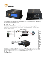
CAD drawing below shows the location of screws for mounting the drive to plate and mounting
the breakout board to the drive.

Turbo Clipper Drive User Manual
Receiving and Unpacking 12
CAD Drawing
Breakout Board
(603926)
2.25
Power Board
(603925)
Clipper Board
(603871)
Ethernet
0.25
5.31
5.125
5.125
Heat Sink

Turbo Clipper Drive User Manual
Receiving and Unpacking 13

Turbo Clipper Drive User Manual
Power board: Wiring, Software Setup 14
POWER BOARD: WIRING, SOFTWARE SETUP
WARNING
Installation of electrical control equipment is subject to
many regulations including national, state, local, and
industry guidelines and rules. General recommendations can
be stated but it is important that the installation be carried
out in accordance with all regulations pertaining to the
installation.
TB1-TB4: Motor Wiring
Motor phases are conversed in one of three conventions. Some motor manufacturers will call the
motor phases A, B, or C. Other motor manufacturers call them U, V, W. The Turbo Clipper
Drive outputs are called U, V, W, and X. For DC brushless motors (servo) use U,V and W, let X
float. For stepper motors, use U and W for one coil, V and X for the other coil. For DC Brush
motors, use U and W, float V and X. The motor’s frame drain wire and the motor cable shield
must be tied together and wired at the GND pin of the motor connector (Pin 5 or 2).
TB1-TB4: Molex (F)
Molex Mating Connector Part #: 39-01-2065 (M)
Molex Crimper Pin Part #: 39-00-0060
For Internal Use:
DT Part #: 014-390120-065
DT Part #: 014-555656-083
Pin #
Symbol
Description
1
U Phase
Axis 1-4
2
GND
Ground
3
V Phase
Axis 1-4
4
W Phase
Axis 1-4
5
GND
Ground
6
X Phase
Axis 1-4
Note
DC Brushless motors: Use U, V and W. Leave X floating
Stepper motors: Use U and W at one coil, V and X at the
other coil.
Brush motors: Use U and W. Leave V and X floating.
The cable wiring must be shielded and have a separate
conductor connecting the motor frame back to the
assembly ground.

Turbo Clipper Drive User Manual
Power board: Wiring, Software Setup 15
TB5: 24-Volt Logic Power
An external 24Vdc power supply is required to power up the logic portion of the Turbo Clipper
Drive. This power can remain on, regardless of the main DC bus power, allowing the signal
electronics to be active while the main motor power control is inactive. The 24V is wired into
terminal block TB5. The polarity of this connection is extremely important. Carefully follow
the instructions in the wiring diagram. This connection can be made using 22 AWG wire
directly from a protected power supply. In situations where the power supply is shared with
other devices, it may be desirable to insert a filter in this connection.
The 24Volts power supply must be capable of providing 2~3Amps per Turbo Clipper Drive to
allow proper functionality. If multiple drives are sharing the same 24Volts power supply, it is
highly recommended to wire each drive back to the power supply terminals separately.
TB5: Molex (F)
Molex Mating Connector Part #: 43025 (M)
Molex Crimper Pin Part #: 43030-0008
For Internal Use:
DT Part #: 014-430250-600
DT Part #: 014-43030-008
Pin #
Symbol
Function
Description
Notes
1
24VDC
Input
Logic power input
+16~32VDC
2
NA
NA
NA
NA
3
24VDC RET
Common
Logic power return
Power Supply Return
4
24VDC
Input
Logic power input
+16~32VDC
5
NA
NA
NA
NA
6
24VDC RET
Common
Logic power return
Power Supply Return

Turbo Clipper Drive User Manual
Power board: Wiring, Software Setup 16
TB6: Bus Voltage
TB6: Molex (F)
Molex Mating Connector Part #:: 50-84-1020 (M)
Molex Crimper Pin Part #: 002081001
For Internal Use:
DT Part #: 014-030f02-HSM
DT Part #: 014-002081-001
Pin #
Symbol
Function
Description
Notes
1
+12~60VDC
Input
Bus power input VBus
+12~60VDC
2
+12~60VDC RET
Common
Bus power return 0Bus
+12~60VDC RET
Recommended Fuse, and wire gauge:
Fuse (FRN/LPN)
Wire Gauge
15
12 AWG

Turbo Clipper Drive User Manual
Power board: Wiring, Software Setup 17
J13: E-Stop, Reset
TB6: Molex (F)
Molex Mating Connector Part #: 430250-0400 (M)
Molex Crimper Pin Part #: 43030-0008
For Internal Use:
DT Part #: 014-430250-400
DT Part #: 014-43030-008
Pin #
Symbol
Description
1
Reset
Connect 1-2 to activate the reset.
2
Reset
3
E-STOP
Connect 3-4 to engage the E-Stop
4
E-STOP
The Turbo Clipper Drive is equipped with a built-in Emergency Stop circuitry. It utilizes two
latching type relays to enable/disable the drive’s Mosfet transistors. Additionally, the following
safety and status features are implemented:
The E-Stop status, by default, is conveyed to the Turbo Clipper via User Flag Input #4
(X:$78018,19).See jumper J39.
The General Purpose Outputs (GPO), by default, is independent of the E-Stop status.
They can be disabled in an emergency stop condition. See jumper J36.
The Turbo Clipper Drive has an E-Stop software controllable enable bit (Y:$78402,15,1).
It is a low true logic meaning =0 to engage E-Stop, =1 to disengage E-Stop, allowing the
user to trigger an emergency stop condition through software logic.
Note
The built-in Emergency Stop circuitry disables the Mosfet
transistors but does NOT remove power from the DC bus. If this
additional level of protection is required, it is recommended to
add a separate external device to remove the DC Bus input from
the Turbo Clipper Drive.

Turbo Clipper Drive User Manual
Power board: Wiring, Software Setup 18
Wiring The E-Stop, And Reset Switch
The E-Stop button should be a normally-closed switch, so
that the circuit is closed when it is released and open when
it is pressed.
The Reset button should be a normally-open switch before
revision 103, so that the circuit is open when it is released
and closed when it is pressed. Revision 103 and after the
type of Reset button can be selectable via jumper E4.
Note
It is recommended to wire the E-
Stop in series with the reset
circuit, so if the machine is in an
emergency stop condition, the
reset cannot be activated and has
no practical use.
E-STOP
Normally
Open
Normally
Closed
RESET
1
2
3
4
J13
Emergency Stop, Reset Jumpers Summary
The following table summarizes the E-Stop and Reset features. The hard E-Stop designates the
actual hardware E-Stop button. The soft E-Stop designates the software controllable E-Stop bit:
Board
Jumper
Function
Default
Power
E1
Remove to enable the hard E-Stop function.
Install to disable the hard E-Stop function.
Not Installed
Power
E2
Remove to enable hard & soft E-Stop functions.
Install to disable hard & soft E-Stop functions.
Not Installed
Power
E3
Remove to enable the soft E-Stop function.
Install to disable the soft E-Stop function
(Soft E-Stop bit has to be set, and saved to 1).
Not Installed
Power
E4
Remove jumper to use normally-open Reset switch
between pin 1 and 2 of J13.
Install jumper to use normally-closed Reset switch
between pin 1 and 2 of J13.
Not Installed
Breakout
J36
Install jumper to disable the GPO E-Stop automatic
feature (outputs unaffected by E-Stop status).
Remove Jumper to enable the GPO E-Stop
automatic feature (turn outputs off when in E-Stop)
Installed
Breakout
J39
Jump 1 to 2 to use User Flag 4 as an E-Stop status
in software.
Jump 2 to 3 to use User Flag 4 as a general purpose
user input.
Jumpered
1-2

Turbo Clipper Drive User Manual
Power board: Wiring, Software Setup 19
Note
Upon releasing the E-Stop, the General Purpose Outputs (GPO)
state, otherwise handled by PLC/software, is re-established to
what it was prior to pressing the E-Stop.
Emergency Stop-Reset Example PLC
In addition to the automatic Emergency Stop functionality a PLC must be used to insure proper
and complete Emergency Stop function once the Mosfet transistors are disabled. During an
emergency stop condition, it is highly advised to implement the following:
Kill motors.
Turn off general purpose outputs (GPOs).
Other functions insuring machine safety.
With E1, E2, E3, and E4 removed allowing both hardware and software E-Stop functionality.
J36 removed, to automatically turn off the general purpose outputs, and J39 set to 1-2 to allow
reading the E-Stop status through User flag4:
// Definition and Substitutions
#define Estop_Latch P8000 ; General purpose Latching flag
#define Estop_Enable M47 ; Software Controllable E-Stop Bit
Estop_Enable->Y:$78402,15,1 ; =0 E-Stop, =1 Not in E-Stop
Estop_Enable=1
#define Estop_Status M415 ; S-Stop Status Bit, using User Flag 4
Estop_Status->X:$78018,19 ; =1 E-Stop, =0 Not in E-Stop
Open PLC 1 Clear
// Is E-Stop Pressed?
If (Estop_Status=1)
Estop_Latch=0
Else
Estop_Latch=1
EndIF
Estop_Enable=1 ; Set once on power-up
While (1=1)
// Emergency Stop Engaged
If(Estop_Status = 1 and Estop_Latch = 0)
// Put Emergency Stop Functions Here
&1 CMD^K ; Kill all axes in Coordinate System 1
// Set desired Outputs state (post E-Stop) here
// if automatic GPO kill is enabled
Estop_Latch = 1
Else
// Emergency Stop Released
IF(Estop_Status = 0 and Estop_Latch = 1)
// Put Emergency Stop Release Functions Here
&1 CMD^A ; Enable all axes in Coordinate System 1
Estop_Latch = 0
P8002=P8002+1
EndIf
EndIf
Endwhile
Close

Turbo Clipper Drive User Manual
Power board: Wiring, Software Setup 20
D1: AMP STATUS
The Turbo Clipper Drive utilizes a scrolling single-digit 7-segment display to exhibit faults to the
outside world. When control and DC bus power are applied, the Drive will display a solid dot
indicating that the software and hardware are running normally.
Error Codes
Display
Description
Global Faults
Under Voltage Fault:
Indicates that the bus voltage is not present or less than 12Volts
Over Voltage Fault:
Indicates that the bus voltage has exceeded 60Volts
Over Temperature Fault:
Indicates that the Board has exceeded 65°C
Axis n Faults (n=1 thru 4)
n
Axis n Over load Fault:
Indicates that the current rating (5/15A) of the drive has been exceeded
n
Axis n Over Current Fault:
Indicates that the peak current value has exceeded the permissible limit(20Amps)
/