Page is loading ...

Laser Emulation

1998 Welch Allyn, Inc. All rights reserved.

Input Power Voltage Requirements
Model Input Power Voltage
3400–X0X
3400/X–X0X
3400LR/F–X0X
5 Volt
ONLY
!
Disclaimer
Welch Allyn
reserves the right to make changes in specifications and other
information contained in this document without prior notice, and the reader
should in all cases consult Welch Allyn to determine whether any such
changes have been made. The information in this publication does not
represent a commitment on the part of Welch Allyn.
Welch Allyn shall not be liable for technical or editorial errors or
omissions contained herein; nor for incidental or consequential
damages resulting from the furnishing, performance, or use of this
material.
This document contains proprietary information which is protected by
copyright. All rights are reserved. No part of this document may be
photocopied, reproduced, or translated into another language without the
prior written consent of Welch Allyn, Incorporated.
This device complies with part 15 of the FCC Rules. Operation is subject to the following two
conditions: (1) this device may not cause harmful interference, and (2) this device must accept
any interference received, including interference that may cause undesired operation.
This equipment has been tested and found to comply with the limits for a Class B digital
device pursuant to part 15 of the FCC Rules. These limits are designed to provide
reasonable protection against harmful interference in a residential installation. This
equipment generates, uses, and can radiate radio frequency energy and, if not installed
and used in accordance with the instructions, may cause harmful interference to radio
communications. However, there is no guarantee that interference will not occur in a
particular installation. If this equipment does cause harmful interference to radio or
television reception, which can be determined by turning the equipment off and on, the
user is encouraged to try to correct the interference by one or more of the following
measures:
FCC Class B Compliance Statement
Caution: Any changes or modifications made to this device that are not expressly
approved by Welch Allyn, Inc. may void the user’s authority to operate the equipment.
Note: To maintain compliance with FCC Rules and Regulations, cables connected to this device must
be
shielded
cables, in which the cable shield wire(s) have been grounded (tied) to the connector shell.
This equipment does not exceed the Class B limits for radio noise emissions as described
in the Radio Interference Regulations of the Canadian Department of Communications.
Canadian Notice
Le present appareil numerique n’emet pas de bruits radioelectriques depassant les limites
applicables aux appareils numeriques de la classe B prescrites dans le Reglement sur le
brouillage radioelectrique edicte par le ministere des Communications du Canada.
• Reorient or relocate the receiving antenna.
• Increase the separation between the equipment and receiver.
• Connect the equipment into an outlet on a circuit different from that to which the
receiver is connected.
• Consult the dealer or an experienced radio or television technician for help.

or
Welch Allyn Ltd.
The Lodge, Tanners Lane
Warrington, Cheshire WA2 7NA
England
European Contact: European Regulatory Manager
Welch Allyn Ltd.
28 Sandyford Office Park
Foxrock, Dublin 18
Ireland
The CE mark on the product indicates that the system has been tested to and
conforms with the provisions noted within the 89/336/EEC Electromagnetic
Compatibility Directive and the 73/23/EEC Low Voltage Directive.
Welch Allyn shall not be liable for use of our product with equipment
(i.e., power supplies, personal computers, etc.) that is not CE marked and
does not comply with the Low Voltage Directive.


1
Table of Contents
TABLE OF CONTENTS
Getting Started
Section Page
Introduction to the 3400 3. . . . . . . . . . . . . . . . . . . . . . . . .
Unpacking the Scanner 4. . . . . . . . . . . . . . . . . . . . . . . . .
Scanner Identification 5. . . . . . . . . . . . . . . . . . . . . . . . . .
Connecting the Scanner 7. . . . . . . . . . . . . . . . . . . . . . . .
Scanning Techniques 9. . . . . . . . . . . . . . . . . . . . . . . . . . .
Product Specifications and Pinouts
Section Page
Environmental Specifications 11. . . . . . . . . . . . . . . . . . . .
Electrical Specifications 11. . . . . . . . . . . . . . . . . . . . . . . . .
Scanner Performance 13. . . . . . . . . . . . . . . . . . . . . . . . . .
Pinouts 15. . . . . . . . . . . . . . . . . . . . . . . . . . . . . . . . . . . . . . .
General Dimensions 16. . . . . . . . . . . . . . . . . . . . . . . . . . . .
Maintenance and Troubleshooting Guide
Section Page
Maintenance 17. . . . . . . . . . . . . . . . . . . . . . . . . . . . . . . . . .
Troubleshooting 19. . . . . . . . . . . . . . . . . . . . . . . . . . . . . . .
Customer Support
Limited Warranty
Sample Bar Codes (inside back cover)

2
Table of Contents

3
Getting Started
GETTING STARTED
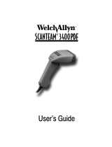
Introduction to the 3400
Note: This document applies to the SCANTEAM 3400 Hand
Held CCD and the SCANTEAM 3400 Long Range
CCD unless otherwise noted.
The SCANTEAM 3400 Series CCD is durable and reliable,
easy to hold and easy to aim. Featuring a unique optics
design without moving parts or a glass mirror, the 3400:
• provides superior first read rate
• reads 5 mil code in close focus (3400–XX1) and 7 mil
code at 3.5” (88.9 mm) (3400LR)
• reads 20 mil code from 0 to 4” [100mm] (3400–XX2)
or 15 mil code from 0 to 6” [152.4 mm] (3400LR)
• scans bar code widths up to 3” [76mm] (3400) and up
to 5” [127 mm] (3400LR).
The 3400 also offers low current consumption to extend the
battery life of portable data terminals.
❖ About This Manual
This user’s guide provides installation instructions for the
Laser Emulation SCANTEAM 3400. Connector pinouts,
product specifications, a troubleshooting guide, warranty
and customer support information are also included.

4
Getting Started
Unpacking the Scanner
Open the carton. The shipping carton should contain:
• Check to make sure everything you ordered is present.
•
Keep the shipping carton to return the scanner for
servicing.
• Check for damage during shipment. Report damage
immediately to the carrier who delivered the carton.

5
Getting Started
Scanner Identification
SCANTEAM 3400 Identification Label
-#". &'%& "#*.'/2 !+"# '* !+*/!/
-#". (+1 "#*.'/2 !+"# $-+) /+ !)
0/+ -'%%#-
*0( -'%%#-
,/'+*
- )%#
.#- 0/
*"
)0(/'+*
-0#
#2 +-"
#"%#
-'+0.
-'+0.
!*.#!+*"
!*.#!+*"
#"%#
➌➍➋
➊
➋
➊
ITEM# 3400/E–102
➍
➌

6
Getting Started
Scanner Identification (3400LR)
SCANTEAM 3400LR Identification Label
(.& +%$$"+
*-%)(
+ '$"
,"+ .-
(!
'.&-%)(
+."
"/)+!
"!$"
+%).,
+%).,
(," )(!
"!$"
➌➍➋
➊
➋
➊
ITEM# 3400LR/F–103
➍
➌
+"!, '"!%.' !"(,%-/ )!", #+)'

7
Getting Started
Connecting the Scanner
Install the scanner by following the steps shown below:
➊ Disconnect power to the terminal/computer by turning
the host system power switch to the “OFF” position.
➋ Connect the interface cable to the scanner and to the
decoder unit attached to your terminal/computer.
1
2

8
Getting Started
➌ Once the scanner has been fully connected, restore
power to the terminal/computer by turning the host
system power switch to the “ON” position.
➍ The 3400 is ready to scan bar code for your application.

9
Getting Started
Scanning Techniques
The scanning technique for a single bar code (on a page or
an object) is shown below.
➊
➋
Move the 3400 Vertically
The illustration below shows where to aim the red
illuminated beam over the bar code for a good read.

10
Getting Started
The scanning technique for multiple bar codes (on a page or
object) is shown below.
➊
➋
Move the 3400 Horizontally
Note: The techniques shown are for a 3400 with automatic
trigger. To scan with a manual trigger, aim the 3400
at a bar code and press the trigger (like step 2).

11
Product Specifications and Pinouts
PRODUCT SPECIFICATIONS AND PINOUTS
Environmental Specifications
parameter specification
Operating Temperature
Storage Temperature
Humidity
Barometric Pressure
Mechanical Shock
ESD Sensitivity
Ambient Illumination
Modular Connector Life
32° F to 122° F [0°C to 50°C]
–40° F to 158° F [–40°C to 70°C]
0% to 95% RH noncondensing
101,000 to 69,000 Pascals
[Sea level to 3,000 meters]
Functional after ten 5ft. [1.5m] drops
Functional after 15KV discharge
3,000 lux (in contact with bar code)
750 insertions/disconnections
Electrical Specifications (3400-XX1, XX2)
parameter specification
Operating Voltage
Current Draw (3400–X0X)
Standby Current (3400/X–1XX)
In–Rush Current
Power Supply Noise Rejection
Acquisition Time (Trigger to Output)
Mean Time Between Failure (MTBF)
5 VDC ±10%
55mA 80mA
less than 3mA
400mA maximum
100mV peak to peak,
from 10 to 100KHz
100msec maximum
50,000 hours (for ground benign)
50 Scans/Sec 100 Scans/Sec5VDC Input
only

12
Product Specifications and Pinouts
Electrical Specifications (3400LR)
parameter specification
Operating Voltage
Current Draw (3400LR/F–103)
Standby Current (3400LR/F–103)
In–Rush Current
Power Supply Noise Rejection
Acquisition Time (Trigger to Output)
Mean Time Between Failure (MTBF)
5 VDC ±10%
140mA
less than 3mA
400mA maximum
100mV peak to peak,
from 10 to 100KHz
100msec maximum
50,000 hours (for ground benign)
50 Scans/Sec5VDC Input
only

13
Product Specifications and Pinouts
Scanner Performance (3400-XX1, XX2)
parameter specification
Pitch Angle
Skew Angle
Minimum Reflective Difference
(MRD)
Scan Rate
Field Width
Horizontal Scan Velocity
Illumination
Working Distance (3400–XX1)
Working Distance (3400–XX2)
Resolution (3400–XX1)
(3400–XX2)
±7 degrees
±30 degrees
37.5%
100 or 50 scans per second
(factory selectable)
2.2 in [55mm] at near contact to
3.0 in [76mm] at 1 in [25mm] from
scanner’s nose
0 to 5 inches [127mm] per second
660 nm Visible Red Light Emitting
Diodes (LED) with focusing reflector
Near contact for high density code
From contact to 4 in [10cm]
for low to medium density code
5 mil [0.127mm] code density minimum
20 mil [0.508mm] code density minimum

14
Product Specifications and Pinouts
Scanner Performance (3400LR)
parameter specification
Pitch Angle
Skew Angle
Minimum Reflective Difference
(MRD)
Scan Rate
Field Width
Horizontal Scan Velocity
Illumination
Working Distance
(3400LR/F–1X3)
Resolution (3400LR/F–1X3)
±7 degrees
±30 degrees
37.5%
50 scans per second
2.2 in [55mm] at near contact to
5.0 in [127mm] at 5 in [127mm]
from scanner’s nose
0 to 5 inches [127mm] per second
660 nm Visible Red Light Emitting
Diodes (LED) with focusing reflector
From contact to 6 in [15.24cm]
for medium density code
7 mil [0.178mm] code density minimum

15
Product Specifications and Pinouts
Pinouts
❖ Laser Output
only:
3400–X0X (Laser Compatible Bar Image)
18
8 Pin RJ41 Modular Connector
Pin
Standard
Welch Allyn
Color Code
Signal
1 N/C
Function
Cord Shield
2 Blue Lasen Laser Enable
3 Black Ground Supply Ground
4 Orange Turn on Good Read LED
or Beeper
Acknowledge
5 Green Digout
6 5 Volt Power Connection+5VDC
7 White Trigger Trigger Signal to Decoder
8 SOS Start of Scan
Braid
Red
Gray
Digital Bar Code Data
Output
(in scanner handle)
❖ Standard Laser Cable: for 3400–X0X
Standard 9 Pin (Type D)
Squeeze–to–Release Connector
Pin
Standard
Welch Allyn
Color Code
Signal
1 SOS
Function
Start of Scan
2 Green Data Digital Bar Code
Signal Output
3 Orange ACK Acknowledge – Good
Read to Scanner
4 Red Power to Scanner+5VDC
5 White Trigger
6 Laser ON Scan Enable
7 Black GRND Ground
8 Shield Cord Shield Only
Grey
Blue
Drain
Trigger to Ground
9 no connection Power to ScannerRed
69
15
Terminating Connector:
(compatible with Welch Allyn terminals)
/

