Page is loading ...

ETC
®
Setup Guide
DMX/RDM One Port Gateway
One Port Gateway Page 1 of 2 Electronic Theatre Controls, Inc.
Corporate Headquarters
3031 Pleasant View Road, P.O. Box 620979, Middleton, Wisconsin 53562-0979 USA
Tel +608 831 4116
Fax +608 836 1736
London, UK
Unit 26-28, Victoria Industrial Estate, Victoria Road, London W3 6UU, UK
Tel +44 (0)20 8896 1000
Fax +44 (0)20 8896 2000
Rome, IT
Via Pieve Torina, 48, 00156 Rome, Italy
Tel +39 (06) 32 111 683
Fax +44 (0) 20 8752 8486
Holzkirchen, DE
Ohmstrasse 3, 83607 Holzkirchen, Germany
Tel +49 (80 24) 47 00-0
Fax +49 (80 24) 47 00-3 00
Hong Kong
Rm 1801, 18/F, Tower 1 Phase 1, Enterprise Square, 9 Sheung Yuet Road, Kowloon Bay, Kowloon, Hong Kong
Tel +852 2799 1220
Fax +852 2799 9325
Service:
(Americas) service@etcconnect.com
(UK) servic[email protected]
(DE) techserv-hoki@etcconnect.com
(Asia) [email protected]
Web:
www.etcconnect.com
Copyright © 2014 ETC. All Rights Reserved.
Product information and specifications subject to change.
4264M2210
Rev A
Released 2014-04
ETC intends this document to be provided in its entirety.
Overview
The DMX/RDM One Port Gateway is a network data distribution device designed for simple
installations with support for Net3 protocols including sACN as well as DMX and Remote Device
Management (RDM). The instructions outlined in this document apply to both Input and Output versions
of the One-Port gateway.
The One-Port DMX Gateway installs into a single gang backbox. It is also available as a Portable
Gateway. The One Port Gateway is powered by 802.3af Power over Ethernet (PoE) or 12-24VDC
power. Network wiring should be installed and terminated by a qualified network installer and follow
standard Ethernet wiring practice.
Configuration for NET3 DMX/RDM gateways is done using NET3 Concert Software. The latest version
is available from www.etcconnect.com
and includes an in-depth help system.
Installation
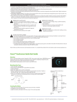
Portable Setup
The portable One Port Gateway is designed for simple setup and can be pipe mounted using the
supplied mounting bracket.
Step 1: Connect a Cat5 Cable (not provided) to the RJ45 connector on the side of the unit.
Wall Mount Setup
Both surface and flush mount installations are acceptable. For
surface mounting, ETC recommends the use of an ETC single
gang surface mount backbox (part# 7081A2004-1). For flush
mounting, ETC recommends the use of RACO #691 backbox
or equivalent (provided by others). All wall-mount gateways
include a standard faceplate but are compatible with any
Decorator style faceplate.
Install the gateway into a backbox
Step 1: Ensure the backbox is clean and free of any
obstructions.
Step 2: Terminate the incoming Cat5 wiring using the
supplied Cat5 termination kit.
wall mount touring
Network
connection
DC power
connection

ETC Setup Guide
One Port Gateway
One Port Gateway Page 2 of 2 Electronic Theatre Controls, Inc.
Step 3: Connect Power to the gateway
• If using PoE for power, plug the supplied RJ45 patch cable (12”/300mm) into the
female RJ45 that you have previously installed into the backbox and the connector
on the One Port Gateway.
• If using DC power, connect the incoming 12-14 VDC power leads to the DC power
terminals on the side of the gateway.
Step 4: Use the included mounting screws to attach the gateway to the backbox.
Install the faceplate
The faceplate assembly includes magnets that secure it to the gateway.
Step 1: Attach the faceplate alignment bracket to the gateway using
the provided screws.
Step 2: Align the top of the faceplate to the gateway with the bottom
edge angled out approximately 20°.
Step 3: Hook the top of the faceplate to the tabs located on the
gateway electronics assembly. The faceplate should stay in
place if wiggled side to side.
Step 4: Pivot the faceplate downward until the magnets engage.
Step 5: If the magnets do not fully engage, wiggle the bottom of the
faceplate until all magnets are properly seated and the
faceplate is secure.
Status and Feedback LEDs
Once properly connected to the network, the LEDs will provide
the following feedback.
Power LED
• A constant blue LED indicates power to the gateway.
Network LED
• A constant green LED indicates a valid network
connection is present.
Status LED
• The status LED may show as red, green or orange depending on the status of the gateway. The
following chart details the possible LED status messages.
Note:
All 1-port Gateways require proper grounding. When installing the gateway in a backbox
that is not grounded, use the included ground wire to connect the gateway to earth
ground.
Solid Orange the port is in Download Mode
Blinking Red sACN cannot be generated because valid DMX is not being received
Solid Red valid DMX is being received
Blinking Green
DMX output cannot be generated because valid sACN is not being
received.
Solid Green valid sACN is being received
LED off the port is off
Power LED
Network LED
Status LED
/