Page is loading ...
SPECIFICATIONS
Power Supply.................. 120VAC, 60Hz or 277VAC, 60Hz
Maximum load rating
@120VAC ....................... 800W max ballast or tungsten
@277VAC ......................................... 1200W max ballast
Horsepower .......................................................... 1/6hp
Dimensions ......... 2.16” front to back x 2.68” W x 1.77” H
(55mm front to back x 68mm W x 45mm H)
Weight ................................................. 2.17 oz. (60 grams)
Environment
Operating temperature .........32° to 131°F (0° to 55°C)
Storage temperature .......‑22° to 158°F (‑30° to 70°C)
Detection indicator .......................................... Green LED
DESCRIPTION
The FS‑755 is a passive infrared (PIR) occupancy sensor
designed to contol lighting where wide‑angle 180° coverage
is desired. It is ideally suited for use in aisleways with
refrigeration systems and freezer cases, vending machines
and display areas. It is designed to turn on cabinet lights
when it detects people in the aisle, then turn the lights off
when the aisle is vacant, after a time delay expires.
It is a line voltage device that controls either 120VAC or
277VAC loads. The FS‑755 fits in a single‑gang wall box and
can be trimmed with a decorator cover plate (not included).
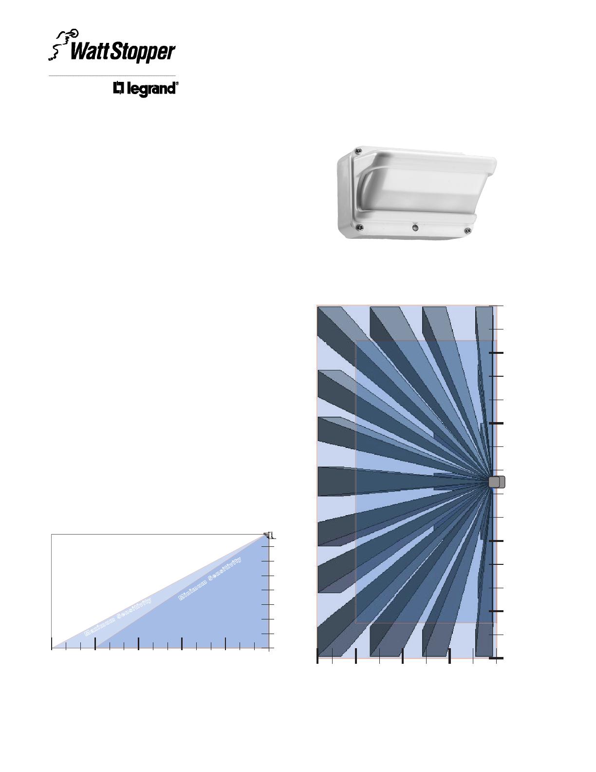
Coverage Pattern
The sensor contains dual pyros and a lens providing 40
detection zones, ensuring dense coverage within the
detection area. The sensor provides true 180° horizontal and
70° vertical coverage.
Side View of coverage pattern
1’
7’
6’
5’
4’
3’
2’
1’2’3’
(0.91m)
4’5’6’
(1.82m)
7’8’9’
(2.74m)
10’11’12’
(3.66m)
13’14’15’
(4.57m)
Maxi mu m Se ns it iv it y
Mi ni mu m Se ns it iv it y
Sensor Mounting Height
Distance
0
Sensor at
7.5’ (2.286m)
FS‑755
Wide‑Angle
Occupancy Sensor
Passive Infrared • Line Voltage
Installation Instructions
Top View of coverage pattern
13’
1’
3’
5’
(1.52m)
7’
9’
11’
(3.35m)
2’4’
(1.22m)
6’8’
(2.43m)
10’12’
(3.66m)
14’
15’
(4.57m)
0
3’
13’
9’
7’
5’
(1.52m)
1’
30’ x 15’ Maximum Sensitivity
24’ x 12’ Minimum Sensitivity
Sensor
15’
(4.57m)
11’
(3.35m)
15’
(4.57m)
www.wattstopper.com Call 866.588.5473 for Technical Support

INSTALLATION
1. Determine an appropriate mounting location for the
FS‑755. For customer display cases, the sensor should be
located above the center of the unit. For walk‑in freezers
or refrigerators, it should be centered above the entry door.
FS-755 centered above front
edge of cabinet, behind
decorator style single-gang
wall plate
Figure 1: Installing above a freezer unit
33mm
1.30”
22mm
0.86”
1.77’
45mm
68mm
2.68”
32mm
1.28”
2. Install a single‑gang wall switch box horizontally in the
mounting location.
3. Connect wiring to the FS‑755 according to the WIRING
instructions.
4. Attach the FS‑755 to the wall switch box using the screws
provided.
5. Attach the decorator cover plate (not included).
6. Apply power to the circuit.
7. Test according to the TEST OCCUPANCY SENSOR
instructions.
WIRING
WARNING
Disconnect power to the wall
box by turning OFF the circuit
breaker or removing the fuse
for the circuit before installing the FS‑755,
replacing lamps, or doing any electrical work.
Install in compliance with all
applicable codes and standards
.
1. Make sure that the power has been turned off at the circuit
breaker.
2. Strip insulation off the wires to expose their copper cores
approximately 1/2“
3. Connect wires to the FS‑755 flying leads as shown in the
wiring diagram.
•ConnecttheGROUNDwirefromthecircuittothegreen
wire on the FS‑755.
•ConnecttheNEUTRALwirefromthecircuittothewhite
wire on the FS‑755.
•Connectthepowerwirefromthecircuitbox(HOT/LINE)
to the black wire on the FS‑755.
•Connectthepowerwirefortheloadtotheredwireonthe
FS‑755.
3. Put the FS‑755 in the wall switch box and secure it to the
box with the screws provided.
4. Attach the cover plate.
5. Restore power to the circuit.
Call 866.588.5473 for Technical Support
White
Neutral
Black
Hot/Line
White
Red
(Load)
FS-755
Model:
Passive Infrared
Occupancy Sensor
Line Voltage
120/277VAC, 60Hz
@120VAC 800W max ballast
or tungsten
@277VAC 1200W max ballast
Horsepower: 1/6hp
1xxxxr1
Santa Clara, CA
800.879.8585
=ON =OFF
234
Time Delay
30 second
5 minutes
10 minutes
20 minutes
1
Sensitivity
Minimum
Maximum
Switch Settings
88T9
Appliance
Control
LISTED
Green
Lighting
load
Black
Switch
(optional)
www.wattstopper.com

ADJUSTMENTS
The Time Delay and PIR Sensitivity
adjustments are located on the back of the
FS‑755 under a removable cover.
The sensors are factory preset for maximum
sensitivity and a 30 second time delay, which
is optimized for use with LED lighting.
For fluorescent loads we recommend at
least 5 minutes for the time delay.
TEST OCCUPANCY SENSOR
Important, there is an initial warm‑up period:
It may take up to a minute for the sensor to warm‑up during the
initial power‑up. During this time, the sensor does not detect
motion.
• If the load is ON when power is applied, it turns OFF within
25 seconds. Approximately 35 seconds after the load turns
off, the sensor starts detecting motion and controlling the
load.
• If the load is OFF when power is applied, the load will stay
off for 60 seconds before the sensor starts detecting and
controlling the load.
1. Set the time delay to minimum (this is the factory preset).
2. Move out of the sensor’s view. Lights should turn off after 30
seconds.
3. Walk down the aisle. When the first sensor detects motion the
green LED in the sensor will flash and the first cooler’s lights
should turn on.
4. Proceed down the aisle, the second cooler’s sensor should
detect you, the green LED in the sensor will flash and the
second cooler’s lights should turn on.
5. This process should continue down the rest of the aisle. As
you walk down the aisle, the cooler lights should progressively
turn on prior to you walking in front of that cooler, turning on
one at a time as you proceed down the aisle.
6. Repeat this process from the opposite end of the aisle. No
matter which direction you approach the system should
function in this way.
TROUBLESHOOTING
The green motion detection LED is located on the front of the
sensor, under the cover plate. Remove the cover plate when
troubleshooting.
Lights will not turn ON:
•SensorLEDdoesnotflashwhenmotioniswithinthecoverage
zone of the detector:
1. Check that the circuit breaker has been turned back on.
2. Check all sensor wire connections.
3. Check for line voltage input to the sensor.
- If line voltage is present, try a different sensor.
- If line voltage is not present, check line wiring.
•SensorLEDdoesflashwhenmotioniswithinthecoverage
zone of the detector:
1. Check all wire connections and verify the load wires are
tightly secured.
2. Check the light switch in the cooler.
3. Check for line voltage on the red load wire.
- If line voltage is present, the sensor is functioning
properly.
- If line voltage is not present, try a different sensor.
* If lights still do not turn ON, call 866‑588‑5473 for technical
support.
Lights will not turn OFF:
The time delay on the sensor can be set from 30 seconds to 20
minutes. Ensure that the time delay is set to the desired delay
and that there is no movement within the sensor’s view for that
time period. To quickly test the unit for proper operation, set
the time delay to 30 seconds and move out of the sensor’s view.
Lights should turn off after 30 seconds.
•IfgreenLEDflasheswhennomotioniswithinthesensor’s
view and the lights do not turn off:
‑ The sensor may be experiencing activations from outside
the controlled area or from some type of interference. Turn
the sensitivity to minimum and allow the sensor to time out.
If the lights turn off, the sensor is working properly.
•IfgreenLEDdoesnotflashwhenmotioniswithinthe
sensor’s view and the lights do not turn off:
1. Check all sensor wire connections.
- If the neutral is not connected the LED will not flash
and the relay will not change state.
2. Check for line voltage input to the sensor.
- If line voltage is present and wiring is correct, try a
different sensor.
- If line voltage is not present, check line wiring.
* If lights still do not turn off, call 866‑588‑5473 for technical
support.
=ON =OFF
234
Time Delay
30 second
5 minutes
10 minutes
20 minutes
1
Sensitivity
Minimum
Maximum
Switch Settings
Call 866.588.5473 for Technical Support
www.wattstopper.com

2800 De La Cruz Boulevard, Santa Clara, CA 95050
Technical Support: 866.588.5473
www.wattstopper.com
10219r1 9/2009
Please
Recycle
WARRANTY INFORMATION
Watt Stopper/Legrand warranties its products to be free of
defects in materials and workmanship for a period of five
(5) years. There are no obligations or liabilities on the part
of Watt Stopper/Legrand for consequential damages arising
out of, or in connection with, the use or performance of this
product or other indirect damages with respect to loss of
property, revenue or profit, or cost of removal, installation or
reinstallation.
ORDERING INFORMATION
FS‑755 Wide‑Angle PIR Sensor, 120/277VAC, 60Hz
Sensors are White
/