Page is loading ...

WS-301/WS-301-347
Passive Infrared Wall Switch
Interrupteur mural avec détecteur de
mouvement à infrarouges passif
Sensor de ocupación con interruptor a la
pared y tecnología de infrarrojo pasivo
Installation Instructions • Instructions d’installation • Instrucciones de instalación
UNIT DESCRIPTION AND OPERATION
The WS‑301 and WS‑301‑347 PIR Wall Switch Occupancy Sensors
turn lighting or fan loads ON and OFF based on occupancy and
ambient light level. They are designed to replace a standard light
switch. The WS‑301 operates with 120 or 277VAC line voltage
and the WS‑301‑347 operates with 347VAC line voltage. All other
features are the same in both models. (Throughout this manual,
“WS” is used to indicate either sensor.)
The sensor uses passive infrared technology to sense human
motion, and defines it as occupancy. A red LED on the sensor
blinks upon occupancy and then resets. It will blink again when it
detects motion after the 2‑second reset.
The sensor turns ON the load automatically when it detects
occupancy. Once the space is vacant and the time delay elapses, it
turns OFF the load automatically.
If adequate ambient light is already present in the area, the
sensor will hold OFF the load it controls. When the light drops
below a field selectable level and the sensor detects occupancy,
the sensor turns ON the load. Once turned ON, the load remains
ON until the space is vacant or the light level rises above the
setpoint and the time delay expires.
Manual Operation
The occupant can press the ON/OFF button to turn the load ON
and OFF. When the load
is turned ON manually,
the sensor will keep the
load ON until no motion is
detected for the length of
the time delay. If the load
is turned OFF manually,
the sensor holds the load
OFF until no motion has
been detected for the
duration of 5 minutes.
The next time the sensor
detects occupancy and the
ambient light is lower than
the set level, the sensor
automatically turns ON the
load.
Walk‑test feature
When the Time Delay trimpot is in the fully counterclockwise
position, the sensor has a 30 second time delay. This allows you to
quickly check the sensor coverage area.
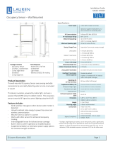
SPECIFICATIONS
WS‑301 Voltages ....................................120 or 277VAC, 50/60Hz
Load Requirements
@ 120VAC .....0~1000W ballast, E‑ballast, LED, tungsten, 1/4 hp
@ 277VAC ............ 0~1200W ballast, E‑ ballast & LED, 1/4 hp
WS‑301‑347 Voltage ..........................................347VAC, 50/60Hz
Load Requirements ..............0~1500W ballast & LED, 1/4 hp
Time Delay Adjustment .........................30 seconds ‑ 30 minutes
Sensitivity Adjustment ................................Minimum‑Maximum
Light Level Adjustment ...............0‑200fc (@4000K) Operating
Temperature ............................................................ 40oC (104oF)
Storage Temperature .............................................. 70oC (158oF)
Terminal screw torque ................................ 16 lbf‑in (18 kgf‑cm)
Optional Neutral Connection
WS-301
WS-301-347
ON/OFF
Switch
Service
Jumper
Light Level
Time Delay
Sensitivity
LED
Fresnel Lens
ON/OFF Button
(Switch Cover)
Press down
on tab and
pry off Cover
(L)
(T)
(S)
Maximum = clockwise
Minimum = counterclockwise
Service function
In the event of unit failure or if it is necessary to leave the load
ON, remove the Service Jumper plug. This disables all automatic
ON and OFF functions and the load can only be operated using the
ON/OFF button.
COVERAGE PATTERNS
The WS detects motion in areas up to 900 sq. ft. and up to 35
feet from the sensor. Ideally, the sensor is designed for small
amounts of motion in spaces up to 300 sq. ft. The Fresnel lens on
the sensor is a multiple segment viewing lens with a field of view
of 180°.
The sensor must have a clear view of the people in the space
in order to detect occupancy. Obstructions, such as furniture
blocking the sensor’s lens, may prevent occupancy detection.
15'
(4.6m)
35'
(10.7m)
4.0'
(1.2m)
35'
(10.7m)
oor
Top View
Side View

Call 800-879-8585 for Technical Support
MASKING THE LENS
Opaque adhesive tape is supplied so that sections of the sensor’s view can be masked. This allows you to
eliminate coverage in unwanted areas. Since masking removes bands of coverage, remember to take this
into account when troubleshooting coverage problems.
INSTALLATION
CAUTION
TURN OFF THE POWER AT THE CIRCUIT
BREAKER BEFORE INSTALLING THE SENSOR.
1. Connect the existing wires in the wall box to the sensor flying leads. (See Wiring Directions).
• Do not allow bare wire to show below connector.
• The ground wire must be tightly grounded for the unit to operate properly.
2. Attach the sensor to the wall by mounting it in the wall box with the two mounting screws provided.
3. Turn ON power at the circuit breaker.
4. Test the sensor using the procedure in the Sensor Adjustments section.
There is an initial warm‑up period after installation. It may take up to a minute before the load turns ON due to a sensor warm‑up
period during initial power‑up (this occurs during installation only). The load turns ON after the warm‑up period ends if the sensor
detects motion.
Rapid successive pressing of the ON/OFF button causes a delay in function. A single press of the button causes an immediate
response. If the button is pressed again within 2 seconds, the switch ignores it if there is not enough power. Wait at least two
seconds between button presses.
5. Install industry standard decorator wall switch cover plate (not included).
WIRING DIRECTIONS
For normal installation of the WS‑301 and WS‑301‑347, connect:
1. LOAD to Red flying lead.
2. LINE to Black flying lead.
3. GROUND to Green.
OPTIONAL NEUTRAL WIRING
For applications requiring neutral wiring, remove tab as shown to expose terminals for wiring.
Opaque tape
Load
Load
Green
Red
Black
Neutral
Optional
Neutral
to Line
Load
Red
Black
Green
Neutral
Optional
Neutral
to Line
Single‑level wiring Manual bi‑level lighting wiring
Strip Gage
1/2"
12.7mm
Cu Wire Only
#12–#14 AWG
Optional neutral
terminals behind
breakaway tab
Breakaway
tab
6" ying leads for
line, load and ground
connections

Visit our web site: www.wattstopper.com
SENSOR ADJUSTMENT
DO NOT OVERTURN TRIMPOTS WHEN
ADJUSTING THE SENSOR!
1. To test unit operation, press the ON/OFF button to turn the load ON.
2. Remove the button cover to access the adjustment controls. Use a small, flat blade
screwdriver to press down the locking tab at the top of the button, then gently pry it off.
a. Set the time delay to the “walk test” position (fully counterclockwise).
b. Leave the room. The load should go OFF after 30 seconds.
3. To test sensitivity:
a. Make no motion for 3 seconds.
b. Wave your hand sideways in front of the sensor at a distance of approximately 12”. The LED blinks when movement is detected.
Typically, the sensitivity should be at maximum (fully clockwise).
4. If desired, set the light level using the steps below. The light level values referenced are approximate and reference 4000K CCT.
Variations in color temperature may affect the actual levels the sensor sees. It is recommended that light level hold off be set up in
the morning for best results. [If this feature is not needed, leave the light level at maximum (fully clockwise)].
a. Set the Time Delay to the “walk test” position (fully counterclockwise).
b. Set the Light level to 50% (12 o’clock position) which is approximately 100fc. Let the sensor time out so lights are OFF. Enter the
space and lights should remain OFF.
c. Make sure your body does not cast a shadow on the sensor, and adjust the light level trimpot clockwise in small increments.
d. After each adjustment, wait 5‑10 seconds to see if the lights turn ON. Repeat until the lights turn ON. At this setting the load
connected to the sensor will not turn ON if light levels are above the current illumination. If you are unable to find the ON position,
your space may be below 100fc. In this case, start your set point below 50%. Typically, most applications would require 100 or
more foot candles.
Note: Users can override this function by placing their hand in front of the sensor to block incoming light. The load will then remain
ON until the space is unoccupied or the light level rises above the setpoint and the time delay expires.
5. Reset the time delay to the desired setting. The time delay can be set from 30 seconds to 30 minutes in 5‑minute increments.
TROUBLESHOOTING
Load will not turn ON:
• LED does not flash:
▸ Check the sensitivity for proper configuration.
▸ Check all wire connections. Verify the ground wire is tightly secured.
• LED does flash:
▸ Press the ON/OFF button. If load does not turn ON, check all wire connections and verify the load
wire is tightly secured.
▸ Check the light level trimpot.
▸ If light level feature is desired, follow the steps from the Sensor Adjustment.
▸ If light level feature is not desired, turn trimpot fully clockwise to disable.
• If load still does not turn ON, call 800.879.8585 for technical support.
Load will not turn OFF:
• The time delay can be set for 30 seconds (Walk Test), 5, 10, 15, 20, 25, or 30 minutes. Ensure that the
time delay is set to the desired delay and that there is no movement within the sensor’s view for that time period.
• To quickly test the unit for proper operation, turn the time delay to minimum (fully counterclockwise) and move out of the sensor’s
view. Load should turn OFF after 30 seconds.
• If load still does not turn OFF, call 800. 879.8585 for technical support.
Sensing motion outside desired area:
• Opaque adhesive tape is included with the sensor and can be used to limit the detection areas. See Masking the Lens.
• Adjust sensitivity counterclockwise to reduce excessive sensitivity.
COVER PLATES
WattStopper WS wall switches fit behind industry standard decorator style switch cover plates.
Time Delay (T)
Shown as set for
15 minutes
30 seconds
(Walk-test)
5 minutes
10 minutes
20 minutes
25 minutes
30 minutes
L
T
S
Sensitivity
(S)
shown as set
for Maximum
Light Level
(L)
shown as set
for Maximum (+)
to disable
Time Delay
(T)
Shown as set for
15 minutes

Call 800-879-8585 for Technical Support

WARRANTY INFORMATION
WattStopper warranties its products to be free of defects in materials and workmanship for a period of five (5) years. There are
no obligations or liabilities on the part of WattStopper for consequential damages arising out of, or in connection with, the use or
performance of this product or other indirect damages with respect to loss of property, revenue or profit, or cost of removal, installation
or reinstallation.
INFORMATIONS RELATIVES À LA GARANTIE
WattStopper garantit que ses produits sont exempts de défauts de matériaux et de fabrication pour une période de cinq (5) ans.
WattStopper ne peut être tenu responsable de tout dommage consécutif causé par ou lié à l’utilisation ou à la performance de ce produit
ou tout autre dommage indirect lié à la perte de propriété, de revenus, ou de profits, ou aux coûts d’enlèvement, d’installation ou de
réinstallation.
INFORMACIÓN DE LA GARANTÍA
WattStopper garantiza que sus productos están libres de defectos en materiales y mano de obra por un período de cinco (5) años.
No existen obligaciones ni responsabilidades por parte de Legrand/WattStopper por daños consecuentes que se deriven o estén
relacionados con el uso o el rendimiento de este producto u otros daños indirectos con respecto a la pérdida de propiedad, renta o
ganancias, o al costo de extracción, instalación o reinstalación.
Phone: 800-879-8585
www.wattstopper.com
Please
Recycle
Pensez au
recyclage
Recicle
2800 De La Cruz Boulevard
Santa Clara, CA 95050
9/2015
21995r1
Detección de movimiento fuera de las áreas deseadas:
• Se proporciona una cinta adhesiva opaca con el sensor que se puede utilizar para limitar las áreas de detección. Consulte la
sección Cómo enmascarar una lente.
• Ajuste la sensibilidad en sentido contrario de las manecillas del reloj para reducir la sensibilidad excesiva.
PLACAS DE LA CUBIERTA
Los interruptores de pared WS encajan detrás de las placas de cubierta de los interruptores con estilo de decoración estándares de la
industria.
/