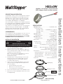
Legrand HB330W, HB340W, HB350W High Bay, Line Voltage, PIR, IP65 Occupancy Sensors Installation guide
- Type
- Installation guide
This manual is also suitable for
Legrand HB330W, HB340W, HB350W High Bay, Line Voltage, PIR, IP65 Occupancy Sensors for Wet Locations are modular sensors designed for automatic lighting control in high bay wet location applications. With a passive infrared sensor (PIR), these sensors detect motion and automatically turn lights on or off based on occupancy. They are ideal for use in warehouses, factories, and other industrial settings where reliable and efficient lighting control is crucial. Here's an overview of their key capabilities:
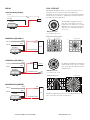
- Interchangeable Lenses: The sensors are compatible with interchangeable lenses, allowing you to customize the coverage area and detection pattern to suit your specific application.
Legrand HB330W, HB340W, HB350W High Bay, Line Voltage, PIR, IP65 Occupancy Sensors for Wet Locations are modular sensors designed for automatic lighting control in high bay wet location applications. With a passive infrared sensor (PIR), these sensors detect motion and automatically turn lights on or off based on occupancy. They are ideal for use in warehouses, factories, and other industrial settings where reliable and efficient lighting control is crucial. Here's an overview of their key capabilities:
- Interchangeable Lenses: The sensors are compatible with interchangeable lenses, allowing you to customize the coverage area and detection pattern to suit your specific application.


-
 1
1
-
 2
2
-
 3
3
-
 4
4


Legrand HB330W, HB340W, HB350W High Bay, Line Voltage, PIR, IP65 Occupancy Sensors Installation guide
- Type
- Installation guide
- This manual is also suitable for
Legrand HB330W, HB340W, HB350W High Bay, Line Voltage, PIR, IP65 Occupancy Sensors for Wet Locations are modular sensors designed for automatic lighting control in high bay wet location applications. With a passive infrared sensor (PIR), these sensors detect motion and automatically turn lights on or off based on occupancy. They are ideal for use in warehouses, factories, and other industrial settings where reliable and efficient lighting control is crucial. Here's an overview of their key capabilities:
- Interchangeable Lenses: The sensors are compatible with interchangeable lenses, allowing you to customize the coverage area and detection pattern to suit your specific application.
Ask a question and I''ll find the answer in the document
Finding information in a document is now easier with AI
Related papers
-
Legrand HB350W-L3 High Bay Line Voltage Occupancy Sensor for Wet Locations Installation guide
-
-
Legrand HB330W Owner's manual
-
-
-
-
-
-
-
Other documents
-
Axis MA1202 Owner's manual
-
wattstopper PW-100 Installation Instructions Manual
-
Sunco Lighting Occupancy Sensor Installation guide
-
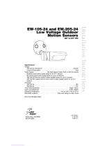 Watt Stopper EW-105-24 Installation Instructions Manual
-
Leviton OSFHP-ILW Operating instructions
-
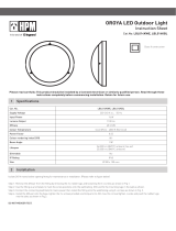 HPM LBL014KWE Operating instructions
-
Intermatic IOS-HB-U Operating instructions
-
Current WASP Occupancy Sensors User manual
-
Lithonia Lighting MSX12 Installation guide
-
Cooper Lighting NeoSwitch - 120/277/347V PIR/Single Level Wall Switch Sensor (Ground Required) Installation guide

