Frick RXF Redesign Installation Operation and Maintenance Guide
- Type
- Installation Operation and Maintenance Guide

RXF
Form 070.410-IOM (MAR 2012)
INSTALLATION - OPERATION - MAINTENANCE
File: SERVICE MANUAL - Section 70
Replaces: 070.410-IOM (JAN 2012)
Dist: 3, 3a, 3b, 3c
Please check www.johnsoncontrols.com/frick for the latest version of this publication.
THIS MANUAL CONTAINS RIGGING, ASSEMBLY, START-UP,
AND MAINTENANCE INSTRUCTIONS. READ THOROUGHLY
BEFORE BEGINNING INSTALLATION. FAILURE TO FOLLOW THESE
INSTRUCTIONS MAY RESULT IN PERSONAL INJURY OR DEATH,
DAMAGE TO THE UNIT, OR IMPROPER OPERATION.

RXF ROTARY SCREW COMPRESSOR UNITS
INSTALLATION - OPERATION - MAINTENANCE
070.410-IOM (MAR 12)
Page 2
TABLE OF CONTENTS
PREFACE.............................................................................3
DESIGN LIMITATIONS ..........................................................3
JOB INSPECTION ................................................................3
TRANSIT DAMAGE CLAIMS ................................................3
UNIT IDENTIFICATION .........................................................3
GEOMETRICAL SWEPT VOLUME TABLE ............................. 4
INSTALLATION
FOUNDATION .....................................................................5
HANDLING and MOVING .....................................................5
SKID REMOVAL...................................................................6
COMPRESSOR/MOTOR COUPLINGS ...................................6
CH COUPLING .....................................................................6
HOLDING CHARGE and STORAGE .......................................6
COMPRESSOR OIL ..............................................................7
OIL CHARGE .......................................................................7
OIL HEATER ........................................................................7
OIL FILTER(S) ......................................................................7
SUCTION ISOLATION VALVE MOUNTING ............................7
THERMOSYPHON OIL COOLING .........................................8
WATER-COOLED OIL COOLING ..........................................8
LIQUID INJECTION OIL COOLING ........................................9
DUAL DIP TUBE METHOD ..............................................10
ECONOMIZER - HIGH STAGE (OPTIONAL) ........................10
ELECTRICAL ......................................................................11
VOLTAGE PROTECTION .................................................. 11
MOTOR STARTER PACKAGE ............................................. 11
MINI MUM BURDEN RATINGS ............................................12
CONTROL POWER REGULATOR ........................................12
OPERATION
OPERATION and START-UP INSTRUCTIONS ..................... 13
RXF COMPRESSOR ...........................................................13
COMPRESSOR LUBRICATION SYSTEM ..............................13
NO PUMP OIL SYSTEM ..................................................13
COLD-START SYSTEM ...................................................13
DEMAND PUMP OIL SYSTEM .........................................14
COMPRESSOR OIL SEPARATION SYSTEM ........................14
COMPRESSOR HYDRAULIC SYSTEM ................................14
CAPACITY CONTROL .....................................................14
VOLUMIZER II Vi CONTROL ........................................... 15
SLIDE VALVE CALIBRATION............................................ 15
COMPRESSOR OIL COOLING SYSTEMS ............................16
SINGLE-PORT LIQUID INJECTION...................................16
DUAL-PORT LIQUID INJECTION .....................................16
QUANTUM™HD EZ-COOL™ LIQUID INJECTION
ADJUSTMENT PROCEDURE .......................................16
OPERATION OF DANFOSS LIQUID INJECTION VALVE ..... 17
THERMOSYPHON OIL COOLING ....................................19
INITIAL START-UP PROCEDURE ........................................19
NORMAL START-UP PROCEDURE .....................................19
VFD SKIP FREQUENCIES ...................................................19
MAINTENANCE
NORMAL MAINTENANCE OPERATIONS ............................22
GENERAL MAINTENANCE .................................................22
COMPRESSOR SHUTDOWN and START-UP ......................22
COMPRESSOR/MOTOR SERVICING ...................................22
GENERAL INSTRUCTIONS FOR REPLACING
COMPRESSOR UNIT COMPONENTS ..............................23
OIL FILTER, SPIN-ON (RXF 12 – 50) .................................23
OIL FILTER, SINGLE ELEMENT (58 – 101) ..........................23
COALESCER OIL RETURN STRAINER .................................24
LI Q UID INJECTION STRAINER ...........................................24
OIL PUMP STRAINER (Optional) .......................................24
SUCTION CHECK VALVE BYPASS ......................................24
COALESCER FILTER ELEMENT ...........................................24
CHANGING OIL .................................................................25
SUCTION STRAINER CLEANING PROCEDURE ....................25
DEMAND PUMP DISASSEMBLY .........................................26
DEMAND PUMP ASSEMBLY ..............................................27
THRUST BEARING ADJUSTMENT ...................................28
INSTALLATION OF CARBON GRAPHITE BUSHINGS ........28
TROUBLESHOOTING THE DEMAND PUMP ........................28
RECOMMENDED MAINTENANCE PROGRAM .....................29
VIBRATION ANALYSIS .......................................................29
OIL QUALITY and ANALYSIS .............................................29
MAINTENANCE SCHEDULE ...............................................30
MOTOR BEARINGS ...........................................................31
OPERATING LOG ...............................................................31
TROUBLESHOOTING GUIDE ..............................................31
ABNORMAL OPERATION ANALYSIS and CORRECTION .....31
PRESSURE TRANSDUCERS - TESTING ..............................32
PRESSURE TRANSDUCERS REPLACEMENT .......................33
SLIDE VALVE TRANSMITTER REPLACEMENT ....................33
TEMPERATURE SENSOR REPLACEMENT ...........................33
OIL LEVEL TRANSMITTER REPLACEMENT ........................34
TEMPERATURE and/or PRESSURE ADJUSTMENT..............34
BARE COMPRESSOR MOUNTING ......................................34
TROUBLESHOOTING THE COMPRESSOR ..........................35
OIL SEPARATOR ............................................................35
LIQUID INJECTION OIL COOLING SYSTEM .....................35
HYDRAULIC SYSTEM ....................................................36
COMPRESSOR PORT LOCATIONS .....................................37
SAE STRAIGHT THREAD O-RING FITTINGS-ASSEMBLY ....39
P & I DIAGRAM .................................................................41
WIRING HARNESS ............................................................46
PROPER INSTALLATION OF ELECTRONIC EQUIPMENT IN
AN INDUSTRIAL ENVIRONMENT ...................................48
WIRE SIZING .................................................................48
VOLTAGE SOURCE .........................................................48
GROUNDING .................................................................49
VFD APPLICATIONS ......................................................49
CONDUIT ......................................................................50
WIRING PRACTICES .....................................................50
COMMUNICATIONS .......................................................52
UPS POWER AND QUANTUM™HD PANELS ....................52
FORMS .............................................................................53

RXF ROTARY SCREW COMPRESSOR UNITS
GENERAL INFORMATION
070.410-IOM (MAR 12)
Page 3
PREFACE
This manual has been prepared to acquaint the owner and
service person with the INSTALLATION, OPERATION, and
MAINTENANCE procedures as recommended by Frick for
RXF Rotary Screw Compres sor Units.
It is most important that these units be properly applied to an
adequately controlled refrigeration system. Your author ized
Frick repre sentative should be consulted for expert guidance
in this determination.
Proper performance and continued satisfaction with these
units is dependent upon:
CORRECT INSTALLATION
PROPER OPERATION
REGULAR, SYSTEMATIC PLANNED MAIN TENANCE
To ensure correct installation and application, the equipment
must be properly selected and connected to a properly de-
signed and installed system. The Engineering plans, piping
layouts, etc. must be detailed in accordance with the best
practices and local codes, such as those outlined in ASHRAE
literature.
A refrigeration compressor is a VAPOR PUMP. To be certain
that it is not being subjected to liquid refrigerant carryover,
it is necessary that refriger ant controls are carefully selected
and in good operating condition; the piping is properly sized
and traps, if necessary, are correctly arrang ed; the suction
line has an accumulator or slugging protec tion; that load
surges are known and provisions made for control; operating
cycles and defrosting periods are reason able; oil return is
controlled; and that high side condenser units control head
pressures and temperatures are within system and compres-
sor design limits.
It is recommended that the entering vapor temperature to
the compressor be superheated to 10°F above the refrigerant
saturation temperature to ensure that all refrigerant at the
compressor suction is in the vapor state.
DESIGN LIMITATIONS
The compressor units are designed for operation within the
pressure and temperature limits as shown in Frick Publica-
tion 070.410-SED.
JOB INSPECTION
Immediately upon arrival examine all crates, boxes, and
exposed compressor and component surfaces for damage.
Unpack all items and check against shipping lists for any
possible shortage. Examine all items for damage in transit.
TRANSIT DAMAGE CLAIMS
All claims must be made by consignee. This is an ICC re-
quirement. Request immediate inspec tion by the agent of
the carrier and be sure the proper claim forms are executed.
Contact Johnson Controls-Frick, Sales Administration
Depart ment, in Waynesboro, PA to report dam age or short-
age claims.
UNIT IDENTIFICATION
Each compressor unit has two identica tion data plates. The
unit data plate containing unit model, serial number and Frick
sales order number is mount ed on the control panel support
bracket. The compressor data plate containing compres sor
model and serial number is mounted on the compressor body.
NOTE: When inquiring about the compressor or unit, or
ordering repair parts, provide the MODEL, SERIAL, and
FRICK SALES ORDER NUMBERS from these data plates.
Indicates an imminently hazardous situation which, if not avoided, will result in death or serious injury.
Indicates a potentially hazardous situation or practice which, if not avoided, will result in death or
serious injury.
SAFETY PRECAUTION DEFINITIONS
Indicates a potentially hazardous situation or practice which, if not avoided, will result in damage
to equipment and/or minor injury.
NOTE: Indicates an operating procedure, practice, etc., or portion thereof which is essential to highlight.
UNIT DATA PLATE

RXF ROTARY SCREW COMPRESSOR UNITS
GENERAL INFORMATION
070.410-IOM (MAR 12)
Page 4
COMPRESSOR DATA PLATE
Rotary screw compressor serial numbers are dened by the
following information:
EXAMPLE: 10240A90000015Z
GLOBAL ADDITIONAL
PLANT DECADE MONTH YEAR SEQ NO. REMARKS
1024 0 A 9 0000015 Z
Month: A = JAN, B = FEB, C = MAR, D = APR, E = MAY, F =
JUN, G = JUL, H = AUG, K = SEP, L = OCT, M = NOV, N = DEC.
Additional Remarks: R = Remanufactured; Z = Deviation from
Standard Conguration.
XJS/XJF 95M 95 1.4 5,772 0.02513 0.000711 89 126
XJS/XJF 95L 95 1.4 4,661 0.03112 0.000881 110 156
XJS/XJF 95S 95 1.4 3,600 0.04086 0.001156 145 205
XJS/XJF 120M 120 1.4 5,772 0.05065 0.001433 180 254
XJS/XJF 120L 120 1.4 4,661 0.06272 0.001775 223 314
XJS/XJF 120S 120 1.4 3,600 0.08234 0.002330 292 412
XJF 151A 151 1.6 6,297 0.09623 0.002723 342 482
XJF 151M 151 1.6 5,332 0.11366 0.003217 403 569
XJF 151L 151 1.6 4,306 0.14075 0.003983 500 705
XJF 151N 151 1.6 3,600 0.16833 0.004764 598 843
GEOMETRICAL SWEPT VOLUME TABLE

RXF ROTARY SCREW COMPRESSOR UNITS
INSTALLATION
070.410-IOM (MAR 12)
Page 5
Installation
FOUNDATION
NOTE: Allow space for servicing both ends of the unit. A
minimum of 24 inches is recommended.
The rst requirement of the compressor foundation is that
it must be able to support the weight of the compressor
package including coolers, oil, and refrigerant charge. Screw
compressors are capable of converting large quantities of
shaft power into gas compression in a relatively small space
and a mass is required to effectively dampen these relatively
high frequency vibrations.
Firmly anchoring the compressor package to a suitable
foundation by proper application of grout and elimination of
piping stress imposed on the compressor is the best insur-
ance for a trouble free installation. Use only the certied
general arrangement drawings from Frick® to determine the
mounting foot locations and to allow for recommended clear-
ances around the unit for ease of operation and servicing.
Foundations must be in compliance with local building codes
and materials should be of industrial quality.
The oor shall be a minimum of 6 inches of reinforced con-
crete and housekeeping pads are recommended. Anchor
bolts are required to rmly tie the unit to the oor. Once the
unit is rigged into place (See HANDLING and MOVING), the
feet must then be shimmed in order to level the unit. The
shims should be placed to position the feet roughly one inch
above the housekeeping pad to allow room for grouting. An
expansion-type epoxy grout must be worked under all areas
of the base with no voids and be allowed to settle with a
slight outward slope so oil and water can run off of the base.
When installing on a steel base, the following guidelines
should be implemented to properly design the system base:
1. Use I-beams in the skid where the screw compressor will
be attached to the system base. They shall run parallel to
the package feet and support the feet for their full length.
2. The compressor unit feet shall be continuously welded to
the system base at all points of contact.
3. The compressor unit shall not be mounted on vibration
isolators in order to hold down package vibration levels.
4. The customer’s foundation for the system base
shall
fully
support the system base under all areas, but most certainly
under the I-beams that support the compressor package.
When installing on the upper oors of buildings, extra precau-
tions should be taken to prevent normal package vibration
from being transferred to the building structure. It may be
necessary to use rubber or spring isolators, or a combination
of both, to prevent the transmission of compressor vibration
directly to the structure. However, this may increase package
vibration levels because the compressor is not in contact with
any damping mass. The mounting and support of suction
and discharge lines is also very important. Rubber or spring
pipe supports may be required to avoid exciting the build-
ing structure at any pipe supports close to the compressor
package. It is best to employ a vibration expert in the design
of a proper mounting arrangement.
In any screw compressor installation, suction and discharge
lines shall be supported in pipe hangers (preferably within
2 feet of vertical pipe run) so that the lines won’t move if
disconnected from the compressor. See table for Allowable
Flange Loads.
1 25 25 25 50 50 50
1.25 25 25 25 50 50 50
1.5 50 40 40 100 75 75
2 100 70 70 150 125 125
3 250 175 175 225 250 250
4 400 200 200 300 400 400
5 425 400 400 400 450 450
6 1,000 750 750 650 650 650
8 1,500 1,000 1,000 1,500 900 900
10 1,500 1,200 1,200 1,500 1,200 1,200
12 1,500 1,500 1,500 1,500 1,500 1,500
14 2,000 1,800 1,800 1,700 2,000 2,000
Proper foundations and proper installation methods are vital;
and even then, sound attenuation or noise curtains may be
required to reduce noise to desired levels.
For more detailed information on Screw Compressor Founda-
tions, please request Frick publication 070.210-IB.
HANDLING and MOVING
This screw compressor package may
be top-heavy. Use caution in rigging
and handling.
RXF 12–50 units can be moved with a forklift or with rigging
and a crane. The recommended method is to insert lengths
of 2" pipe through the base tubing (see Figure 1 below).
Spreader bars should be used on
both the length and width of the
package to prevent bending oil lines
and damage to the package. CAUTION must also be used
in locating the lifting ring. Appropriate adjust ment in the
lifting point should be made to compensate for motor
weight. Adjustment of the lifting point must also be made
for any additions to the standard package such as an
external oil cooler, etc., as the center of balance will be
effected.
Figure 1 - RXF 12 – 50
The unit can be moved with a forklift by forking through
the base tubing. NEVER MOVE THE UNIT BY PUSHING
OR FORKING AGAINST THE SEPARATOR SHELL OR ITS
MOUNT ING SUPPORTS.

RXF ROTARY SCREW COMPRESSOR UNITS
INSTALLATION
070.410-IOM (MAR 12)
Page 6
COMPRESSOR/MOTOR COUPLINGS
RXF units are arranged for direct motor drive and include a
exible drive coupling to connect the compressor to the motor.
CH COUPLING
The T. B. Woods Elastomeric Type
CH Coupling is used in most appli-
cations. This coupling consists
of two drive hubs and a gear-
type Hytrel, EDPM, or neo-
prene drive spacer. The split
hub is clamped to the shaft by
tightening the clamp screws.
Torque is transmitted from the
motor through the elastomeric
gear which oats freely between the
hubs. Because of the use of the motor/compressor adapter
housing on the RXF, no eld alignment is necessary.
It is mandatory that the coupling
center be removed and the direction
of motor rotation be confirmed
before running the compressor. Proper rotation of the
compressor shaft is clockwise looking at the end of the
compressor shaft. Failure to follow this step could result
in backward compressor rotation which can cause com-
pressor failure or explosion of the suction housing.
1. Inspect the shaft of the motor and compressor to ensure
that no nicks, grease, or foreign matter is present.
2. Inspect the bores in the coupling hubs to make sure that
they are free of burrs, dirt, and grit.
3. Check that the keys t the hubs and shafts properly.
4. Slide one hub onto each shaft as far as possible. It may
be necessary to use a screwdriver as a wedge in the slot to
open the bore before the hubs will slide on the shafts.
5. Hold the elastomeric gear between the hubs and slide both
hubs onto the gear to fully engage the mating teeth. Center
the gear and hub assembly so there is equal engagement on
both shafts. Adjust the space between hubs as specied in
the CH Coupling Data Table below. NOTE: The center sec-
tion will be a little loose between the hubs. This allows
for growth during operation.
6. Torque the clamping bolts in both hubs to the torque value
given in the CH Data Table. DO NOT USE ANY LUBRICANT
ON THESE BOLTS.
HOLDING CHARGE and STORAGE
Each compressor unit is pressure and leak tested at the John-
son Controls-Frick factory and then thoroughly evacuated and
charged with dry nitrogen to ensure the integrity of the unit
during shipping and short term storage prior to installation.
RXF 58 – 101 units can be moved with rigging, using a crane
or forklift by hooking into three lifting points on the oil sepa-
rator. See Figure 2.
Spreader bars may be required on
both the length and width of the
package to prevent bending oil lines
and damage to the package. CAUTION must also be used
in locating the lifting ring. Appropriate adjust ment in the
lifting point should be made to compensate for motor
weight. Adjustment of the lifting point must also be made
for any additions to the standard package such as an
external oil cooler, etc., as the center of balance will be
affected.
Figure 2 - RXF 58 – 101
The unit can be moved with a forklift by forking under
the wooden skid (if provided), or it can be skidded into
place with pinch bars by pushing against the skid. NEVER
MOVE THE UNIT BY PUSHING OR FORKING AGAINST THE
SEPARAT OR SHELL OR ITS MOUNTING SUPPORTS.
SKID REMOVAL
This screw compressor package may
be top-heavy. Use caution to pre-
vent unit from turning over.
If the unit is rigged into place, the wooden skid can be re-
moved by taking off the nuts and bolts that are fastening the
unit mounting supports to the skid before lowering the unit
onto the mounting surface.
If the unit is skidded into place, remove the cross mem bers
from the skid and remove the nuts anchoring the unit to the
skid. Using a 10-ton jack under the separator, raise the unit
at the compressor end until it clears the two mounting bolts.
Spread the skid to clear the unit mounting support, then lower
the unit to the surface. Repeat proced ure on opposite end.
CH COUPLING DATA TABLE
Coupling Hub
CH Between Shaft Spacing Shaft Engagement Face
Spacing
Clamp Bolt Keyway
Series Min. Max. Min. Max.
Torque (Dry)
Size Setscrew Torque Size
Size In. mm In. mm In. mm In. mm In. mm Ft-Lb Nm Ft-Lb Nm UNC
6 2 50.8 2¾ 69.9 1 25.4 1ZB\zn 49.2 7/8 22.2 15 20.3 1/4-20 UNC 13 17.6 5/16-18
72B\zn 58.7 3M\zn 87.3 1 25.4 2C\zn 55.6 1Z\zn 27.0 30 40.7 5/16-24 UNF 13 17.6 5/16-18
82>\zn 65.1 4 101.6 1Z\zn 27.0 2½ 63.5 1Z\, 28.6 55 74.6 3/8-24 UNF 13 17.6 5/16-18
93Z\zn 77.8 4B\, 117.5 1M\zn 36.5 3 76.2 1M\zn 36.5 55 74.6 3/8-24 UNF 13 17.6 5/16-18
10 3>\zn 90.5 5¼ 133.4 1ZZ\zn 42.9 3½ 88.9 1ZZ\zn 42.9 130 176.3 1/2-20 UNF 13 17.6 5/16-18

RXF ROTARY SCREW COMPRESSOR UNITS
INSTALLATION
070.410-IOM (MAR 12)
Page 7
NOTE: Care must be taken when entering the unit to
ensure that the nitrogen charge is safely released.
Holding charge shipping gauges on
separator and external oil cooler are
rated for 30 PSIG and are for check-
ing the shipping charge only. They must be removed
before pressure testing the system and before charging
the system with refrigerant. Failure to remove these
gauges may result in catastrophic failure of the gauge and
uncontrolled release of refrigerant resulting in serious
injury or death.
All units must be kept in a clean, dry location to prevent
corrosion damage. Reasonable consideration must be given
to proper care for the solid-state components of the mi-
croprocessor.
Units which will be stored for more than two months must
have the nitrogen charge checked periodically. Contact
Johnson Controls-Frick for long term storage procedure.
COMPRESSOR OIL
DO NOT MIX OILS of different
brands, manufacturers, or types.
Mixing of oils may cause excessive
oil foaming, nuisance oil level cutouts, oil pressure loss,
gas or oil leakage and catastrophic compressor failure.
NOTE:
The oil charge shipped with the unit is the best
suited lubricant for the conditions specied at the time
of purchase. If there is any doubt due to the refrigerant,
operating pressures, or temperatures; refer to Frick pub-
lication 160.802-SPC for guidance.
OIL CHARGE
The normal charging level is midway in the top sight
glass located midway along the oil separator shell. Normal
operat ing level is between the top sight glass and bottom
sight glass. Oil charge quantities are as follows:
BASIC ADDITIONAL FOR
RXF CHARGE OIL COOLER
MODEL (gallon) (gallon)
12 – 19 10 1
24 – 50 11 1
58, 68 25 3½
85, 101 36 3½
Add oil by attaching the end of a suitable pressure type
hose to the oil drain valve (see Figure 3), located under the
oil separator. Using a pressure-type pump and the recom-
mended Frick® oil, open the drain valve and pump oil into
the separator. NOTE: Evacuation of the oil separator will
assist the ow of oil into the unit. Also, ll slowly because
oil will ll up in the separator faster than it shows in the
sight glass.
Oil distillers and similar equipment which trap oil must be
lled prior to unit operation to normal design outlet levels.
The same pump used to charge the unit may be used for
lling these auxiliary oil reservoirs.
The sight glass located near the bottom of the separator shell
at the discharge end should remain empty when the unit is
in operation. The presence of oil in this end of the vessel
during operation indicates liquid carryover or malfunc tion
of the oil return.
Figure 3 - Oil Drain Valve
OIL HEATER
Standard units are equipped with 500 watt oil heaters, which
provide sufcient heat to maintain the oil tempera ture for
most indoor applications during shutdown cycles and to
permit safe start-up. RXF 12–50 use one heater while mod-
els 58–101 use two. Should additional heating capacity be
required because of an unusual environmental condition,
contact Johnson Controls-Frick. The heater is energized only
when the unit is not in operation.
Do not energize the heater when there
is no oil in the unit, otherwise the
heater will burn out. The oil heater
will be energized whenever 120 volt control power is applied
to the unit and the compressor is not running, unless the
16 amp circuit breaker in micro enclosure is turned off (or
15 amp fuse (1FU) in the Plus panel is removed).
OIL FILTER(S)
Use of lter elements other than
Frick may cause warranty claim to
be denied.
The oil lter(s) and coalescer lter element(s) shipped with
the unit are best suited to ensure proper ltration and op-
eration of the system.
SUCTION ISOLATION VALVE MOUNTING
The suction isolation valve is shipped loose from the factory,
so it can be installed at various positions within the suction
line piping to the compressor. DO NOT INSTALL the valve at
the compressor suction with ow against the cone/button
(see Figure 4 TOP). When the isolation valve is installed in
this position, uneven ow is generated across the suction
check valve which is mounted at the inlet to the compressor.
This uneven ow causes the disks in the check valve to strike
against the stop pin, and eventually damage the internals
of the check valve. If the isolation valve is mounted at the
compressor suction, DO INSTALL with ow across the cone/
button (see Figure 4 BOTTOM). Please design your system
piping accordingly.

RXF ROTARY SCREW COMPRESSOR UNITS
INSTALLATION
070.410-IOM (MAR 12)
Page 8
INCORRECT!
CORRECT!
Figure 4 - Suction Isolation Valve Mounting
THERMOSYPHON OIL COOLING
EQUIPMENT: The basic equipment required for a thermo-
syphon system consists of:
1. A source of liquid refrigerant at condens ing pressure and
temperature located in close prox imity to the unit to minimize
piping pressure drop.
The liquid level in the refrigerant source must be 6 to 8 feet
above the center of the oil cooler.
2. A shell and tube or plate-type oil cooler with a minimum
300 psi design working pressure on both the oil and refrig-
erant sides.
Due to the many variations in refrigeration sys tem design
and physical layout, several systems for assuring the above
two criteria are possible.
INSTALLATION: The plate-type thermo syphon oil cooler with
oil side piping and a thermo statical ly controlled mixing valve
are factory mounted and piped. See Figure 5.
Figure 5 - Thermosyphon Oil-Cooled System
1.
Thermosyphon oil cooler is supplied with oil side piped to
the compressor unit and socket weld ends supplied on the
refrigerant side.
2. A refrigerant-side safety valve is required when refriger-
ant isolation valves are installed between the cooler and
thermosyphon receiver. If no valves are used between the
cooler and thermosyphon receiver, the safety valve on the
thermosyphon receiver must be sized to handle the volume
of both vessels. Then, the safety valve on the cooler vent
(liquid refrigerant side) can be eliminated.
3. System receiver must be mounted below thermosyphon
receiver level in this arrangement.
4. The refrigerant source, thermosyphon or system receiver,
should be in close proximity to the unit to minimize piping
pressure drop.
5. The liquid level in the refrigerant source must not be less
than 6 feet above the center of the oil cooler.
6. Frick recommends the installation of an angle valve in the
piping before the thermosyphon oil cooler to balance the
thermosyphon system. Frick also recommends the instal-
lation of sight glasses at the TSOC inlet and outlet to aid in
troubleshooting. The factory-mounted plate-type thermo-
syphon oil cooler requires a refrigerant-side drain valve to
be provided and installed by the customer.
The component and piping arrangement shown in Figure 5 is
intended only to illustrate the operating principles of thermo-
syphon oil cooling. Other component layouts may be better
suited to a specic installation. Refer to publication 070.900-E
for additional information on Thermosyphon Oil Cooling.
WATER-COOLED OIL COOLING
The plate-type water-cooled oil cooler is mounted on the
unit complete with all oil piping. The customer must supply
adequate water to the oil cooler.
Johnson Controls-Frick recommends a closed-loop system
for the waterside of the oil cooler. Careful attention to water
treatment is essential to ensure adequate life of the cooler
if cooling tower water is used. It is imperative that the con-
dition of cooling water and closed-loop uids be analyzed
regularly and as necessary and maintained at a pH of 7.4, but
not less than 6.0 for proper heat exchanger life. After initial
start-up of the compressor package, the strainer at the inlet
of the oil cooler should be cleaned several times in the rst
24 hours of operation.
In some applications, the plate-type oil cooler may be sub-
jected to severe water conditions, including high temperature
and/or hard water conditions. This causes accelerated scal-
ing rates which will penalize the performance of the heat
exchanger. A chemical cleaning process will extend the life
of the heat exchanger. It is important to establish regular
cleaning schedules.
Cleaning: A 3% solution of Phosphoric or Oxalic Acid is rec-
ommended. Other cleaning solutions can be obtained from
your local distributor, but they must be suitable for stainless
steel. The oil cooler may be cleaned in place by back ushing
with recommended solution for approximately 30 minutes.
After back ushing, rinse the heat exchanger with fresh water
to remove any remaining cleaning solution.

RXF ROTARY SCREW COMPRESSOR UNITS
INSTALLATION
070.410-IOM (MAR 12)
Page 9
Figure 7 - Maximum static forces and moments
LIQUID INJECTION OIL COOLING
The liquid injection system provided on the unit is self-con-
tained but requires the connection of the liquid line sized as
shown in the table.
Liquid line sizes and the additional receiver volume (quanti-
ty of refrigerant required for 5 minutes of liquid injection oil
cooling) are given in the following table:
CONDITIONS: High Stage at 0°F Evap, and 95°F Cond, 10°F
suction superheat; Booster at -40°F Evap, 95°F Cond, 20°F
Intermediate, and 10°F suction superheat; R-507 unloaded
slide valve.
RXF LIQ. LINE SIZE* 5 MIN LIQUID
REFRIG MODEL PIPE TUBING SUPPLY
VOLUME
SCH 80 OD
POUNDS
CU. FT
R-717
HIGH
STAGE
12-19 3/8 – 12 0.3
24-50 1/2 – 33 0.9
58-101 3/4 – 65 1.8
R-507
HIGH
STAGE
12-19 3/8 1/2 24 0.4
24-50 3/8 1/2 60 1.0
58-101 1/2 5/8 99 1.6
R-717
BOOSTER
12-19 3/8 – 3 0.1
24-50 3/8 – 8 0.2
58-101 3/8 – 14 0.4
R-507
BOOSTER
12-19 No oil heat of rejection
at this condition
24-50
58-101
* 100 ft. liquid line. For longer runs, increase line size accordingly.
High-stage compressor units may be supplied with single-port
(low Vi, side, or closed thread) or dual-port (low Vi and high Vi),
liquid injection oil cooling. Single port will be furnished for low
compression ratio operation and dual port for high compres-
sion ratio operation. Booster compressor units use single-port
(High Vi), liquid injection oil cooling due to the typically lower
compression ratios.
The control system on high-stage units with dual-port, liquid
injection oil cooling switches the liquid refrigerant supply to
the high port when the compres sor is operating at higher
compression ratios (3.5 Vi and above) for best efciency.
FIELD WELDING INSTRUCTIONS FOR TSOC AND WCOC:
The heat exchanger body is constructed in stainless steel,
while the stub connections are carbon steel. The highly
polished stub connections can give the appearance of stain-
less steel. The following are requirements for welding to the
socket weld ttings on Plate heat exchangers:
1. Use a heat sink paste around the base of the connection.
These are available from a number of suppliers of welding
materials.
Heat-sink paste must be applied
around the base of the connection
prior to welding. See Figure 6.
2. Two-pass welding is required; stagger start/stop region;
welding procedure in accordance with ASME Section 9.
3. If possible use gas protection, when welding, to avoid
oxidation of the surface. As it is rarely possible to clean the
root side of the weld by grinding or brushing to remove the
root oxide, it is optimal to use root gas.
4. Welding should occur in two segments, from 6:00 to 12:00.
The maximum intersegment temperature should be 350°F.
Temperature should be veried with temperature indicating
crayon or equivalent.
5. The tting may be cooled with forced air to reduce the
temperature of the tting to 350°F or lower, prior to welding
the second segment.
The maximum connection static forces and moments for Alfa
Nova heat exchangers are listed in the following table.Keep
these values in mind when designing your system. It is also
recommended to minimize connection loads when designing
piping systems. Also see Figure 7.
Fx Fy Fz Mx My Mz
(lbf) (lbf) (lbf) (lbfft) (lbfft) (lbfft)
ANHP52 202 13 13 57 32 32
ANHP76 292 22 22 103 58 58
.
Figure 6 - Application of heat-sink paste before welding

RXF ROTARY SCREW COMPRESSOR UNITS
INSTALLATION
070.410-IOM (MAR 12)
Page 10
Figure 10 - Direct Expansion Economizer System Figure 12 - Multiple Compressor Flash Economizer System
ECONOMIZER - HIGH STAGE (OPTIONAL)
The economizer option provides an increase in system capac-
ity and efciency by subcooling liquid from the condenser
through a heat exchanger or ash tank before it goes to the
evapora tor. The subcooling is provided by ashing liquid in
the economizer cooler to an intermediate pressure level.The
intermediate pressure is provided by a port located part way
down the compres sion process on the screw compressor.
As the screw compressor unloads, the economizer port will
drop in pressure level, eventually being fully open to suc-
tion. Because of this, an output from the microproces sor is
generally used to turn off the supply of ashing liquid on a
shell and coil or DX economizer when the capacity falls below
approximately 60%-70% (85%-90% slide valve position). This
is done to improve compressor operating efciency. Please
note however that shell and coil and DX economizers can be
used at low compressor capaciti es in cases where efcien-
cy is not as important as ensuring that the liquid supply is
subcooled. In such cases, the economi zer liquid solenoid can
be left open whenever the com pressor is running.
Due to the tendency of the port pressure to fall with de-
creasing compressor capacity, a back-pressure regulator
valve (BPR) is generally required on a Flash Economizer
System (Figure 11) in order to maintain some preset pressure
dif ference between the subcooled liquid in the ash vessel
and the evaporato rs. If the back-pressure regulator valve is
not used on a ash economizer, it is possible that no pressure
difference will exist to drive liquid from the ash vessel to the
evaporators, since the ash vessel will be at suction pressure.
In cases where wide swings in pressure are anticipated in
the ash econo mizer vessel, it may be necessary to add an
outlet pressure regulator to the ash vessel outlet to avoid
overpressurizing the economizer port, which could result
in motor overload. Example: A system feeding liquid to the
ash vessel in batches.
Figure 9 - Shell And Coil Economizer System Figure 11 - Flash Economizer System
Where low compres sion ratios (low condensing pressures)
are anticipated, thermo syphon or water-cooled oil cooling
should be used.
It is imperative that an uninter-
rupted high-pres sure liquid refrig-
erant be provided to the injection
system at all times. Two items of EXTREME IMPORTANCE
are the design of the receiver/liquid injection supply and
the size of the liquid line. It is recommended that the
receiver be oversized sufciently to retain a 5-minute
supply of refrigerant for oil cooling. The evaporator sup-
ply must be secondary to this considera tion. Failure to
follow these requirements causes wire draw which can
result in damage to the expansion valve, loss of oil cool-
ing, and intermittant oil cooling. One method of ac-
complishing this is described below.
DUAL DIP TUBE METHOD
The dual dip tube method uses two dip tubes in the re ceiv-
er. The liquid injection tube is below the evaporator tube to
assure continued oil cooling when the receiver level is low.
See Figure 8.
Figure 8

RXF ROTARY SCREW COMPRESSOR UNITS
INSTALLATION
070.410-IOM (MAR 12)
Page 11
The recommended economizer systems are shown in Figures
9 – 12. Notice that in all systems there must be a strainer
and a check valve between the economizer vessel and the
economizer port on the compressor. The strainer prevents
dirt from passing into the compressor and the check valve
prevents oil from owing from the compressor unit to the
econo mizer vessel during shutdown.
Other than the isolation valve
needed for strainer cleaning, it
is essential that the strainer be the
last device in the economizer line before the compres sor.
The strainer must be strong enough to handle the gas
pulsations from the compressor. Johnson Controls-Frick
recommends an R/S or Hansen strainer. Also, piston-type
check valves are recom mended for installation in the
economizer line, as opposed to disc-type check valves.
The latter are more prone to gas-pulsation-induced fail-
ure. The isolation and check valves and strainer should
be located as closely as possible to the compressor, pref-
erably within a few feet.
For refrigeration plants employing multiple compressors on
a common economizing vessel, regardless of economizer
type, each compressor must have a back-pressure regulat-
ing valve in order to balance the economizer load, or gas
ow, between compressors. The problem of balancing load
becomes most important when one or more compressors
run at partial load, exposing the economizer port to suction
pressure. In the case of a ash vessel, there is no need for
the redundancy of a back-pressure regulating valve on the
vessel and each of the multiple compressors. Omit the BPR
valve on the ash economizer vessel and use one on each
compressor, as shown in Figure 12.
ELECTRICAL
NOTE: Before beginning electrical installation, read the
instructions in the section "Proper Installation of Elec-
tronic Equipment" at the back of this manual.
RXF units are supplied with a Quantum™HD control system.
Care must be taken that the controls are not exposed to
physical damage during handling, storage, and installa tion.
The single-box control door must be kept tightly closed to
prevent moisture and foreign mat ter from entry.
Customer connections are made in
the Quantum™HD control
panel* mounted on the unit. The
electrical enclosures should be kept tightly closed when-
ever work is not being done inside. * Or starter panel (if
provided).
VOLTAGE PROTECTION
Johnson Controls-Frick® does not advise nor support the
use of UPS power systems in front of the Quantum™HD
panel. With a UPS power system providing shutdown protec-
tion for the Quantum™HD, the panel may not see the loss
of the 3-phase voltage on the motor because the UPS could
prevent the motor starter contactor from dropping out. With
the starter contactor still energized, the compressor auxiliary
will continue to feed an “Okay” signal to the panel. This will
allow the motor to be subjected to a fault condition on the
3-phase bus. Some fault scenarios are:
1. The 3-phase bus has power “on” and “off” in a continu-
ous cyclic manner which may cause the motor to overheat
due to repeated excessive in-rush currents.
2. Motor cycling may damage the coupling or cause other
mechanical damage due to the repeated high torque motor
“bumps”.
3.
Prolonged low voltage may cause the motor to stall and
overheat before the motor contactor is manually turned off.
Under normal conditions, the loss of 3-phase power will shut
down the Quantum™HD panel, and it will restart upon power
return. If the panel was in:
• Auto – Compressor motor will return to running as pro-
grammed.
• Remote – The external controller would reinitialize the
panel and proceed to run as required.
• Manual – The compressor will have to be restarted
manually after the 3-phase bus fault has been cleared.
If the local power distribution system is unstable or prone
to problems, there are other recommendations to satisfy
these problems. If power spikes or low or high line voltages
are the problem, then we recommend the use of a Sola®
constant voltage (CV) transformer with a line suppression
feature. If a phase loss occurs, then you will typically get a
high motor amp shutdown. If problems continue to exist, then
an examination of the plant’s power factor may be in order.
Unless careful design failure analysis is considered in the
implementation of power systems, the alternative solutions
provide a safer and less expensive implementation. In either
case, only one Sola® may be used per compressor. Each
compressor needs to be individually isolated from each other
through a dedicated control transformer. Sharing a common
control power source is an invitation for ground loops and
the subsequent unexplainable problems.
MOTOR STARTER PACKAGE
When starting at full voltage or
across-the-line, a shunting device
must be installed or the Analog I/O
board in the Quantum™HD panel may be severely damaged
at start-up. See Figure 13.
Motor starter and interlock wiring require ments are shown
in the diagram, Figure 12. All of the equipment shown is sup-
plied by the installer unless a starter package is pur chased
separately from Frick. Starter packages should consist of:
1. The compressor motor starter of the specied horse-
power and voltage for the starting method specified
(across-the-line, autotransformer, wye-delta or solid-state).
NOTE: If starting methods other than across-the-line are
desired, a motor/compres sor torque analysis must be done
to ensure sufcient starting torque is available. Contact
Frick if assist ance is required.
2. If specied, the starter package can be sup plied as a com-
bination starter with circuit breaker disconnect. How ever,
the motor overcurrent protection/discon nec tion device can
be applied by others, usually as a part of an electrical power
distribution board.
3. A 3.0 KVA control power transformer (CPT) to supply 120
volt control power to the control system and separator oil
heaters is included. If environmental conditions require more
than 2000 watts of heat, an appro priately oversized control
trans former will be required.

RXF ROTARY SCREW COMPRESSOR UNITS
INSTALLATION
070.410-IOM (MAR 12)
Page 12
4. One normally open compressor motor starter auxiliary
contact should be supplied and wired as shown on the starter
package wiring diagram. In addition, the compressor starter
coil and the CPT secondaries should be wired as shown on
the starter package wiring diagram, Figure 13.
Figure 13 - Starter Wiring Diagram
Figure 14 - Point-to-Point Wiring Diagram
5. The compressor motor Current Transformer (CT) can be
installed on any one phase of the compressor leads. NOTE:
the CT must see all the current on any one phase, there-
fore in wye-delta applications BOTH leads of any one
phase must pass through the CT.
CURRENT TRANSFORMER SIZE
Calculate (CT) size using the following formula where SF is
Service Factor and FLA is Full Load Amps of the Motor.
FLA x SF x 1.1
(round up to the next hundred)
Example: FLA = 379; Service Factor = 1.15
379 x 1.15 x 1.1 = 479
Use a 500:5 CT
DO NOT use undersized current transformers since the panel
will not be capable of reading potential current. If the CT is
higher than calculated, enter it's value for [CT Factor] on the
panel. The unit can operate with a CT one size larger than
calculated, however, replace with the proper size ASAP. DO
NOT operate unit with a CT more than one size larger
than recommended.
MINI MUM BURDEN RATINGS
The following table gives the minimum CT burden ratings.
This is a function of the distance between the motor starting
package and the compressor unit.
B-0.1 2.5 15 ft 25 ft 40 ft
B-0.2 5 35 ft 55 ft 88 ft
B-0.5 12.5 93 ft 148 ft 236 ft
NOTE: Do not install a compressor HAND/OFF/AUTO
switch in the starter package as this would bypass the
compressor safety devices.
CONTROL POWER REGULATOR
Compressor units that will be used in areas that suffer brown-
outs and other signicant power uctuations can be supplied
with a control power regulator. See Figure 15, Recommended
Regulator Installation.
Figure 15 - Recommended Regulator Installation

RXF ROTARY SCREW COMPRESSOR UNITS
OPERATION
070.410-IOM (MAR 12)
Page 13
Operation
OPERATION and START-UP INSTRUCTIONS
The Frick RXF Rotary Screw Compressor Unit is an integrat ed
system consisting of six major subsystems:
Control Panel – See publications 090.040-O, M, & CS for
QUANTUM
™
HD; Compressor; Compressor Lubrication System;
Compressor Oil Separation System; Compressor Hydraulic
System; Compressor Oil Cooling System.
The information in this section of the manual provides the
logical step-by-step instructions to properly start up and
operate the RXF Rotary Screw Compressor Unit.
NOTE: For alarm descriptions and shutdown or cutout
parameters, see publication 090.040-O.
THE FOLLOWING SUBSECTIONS
MUST BE READ AND UNDERSTOOD
BEFORE ATTEMPTING TO START OR
OPERATE THE UNIT.
RXF COMPRESSOR
The Frick RXF rotary screw compressor utilizes mating asym-
metrical prole helical rotors to provide a continuous ow of
refriger ant vapor and is designed for high pressure applica-
tions. The compres sor incorporates the following features:
1. High capacity roller bearings to carry radial loads at both
the inlet and outlet ends of the compressor.
2. Heavy-duty angular contact ball bearings to carry axial
loads are mounted at the discharge end of compressor.
3. Moveable slide valve to provide innite step capacity
control from 100% to 25% of full load capacity.
4. VOLUMIZER II adjusts to the most efcient of three volume
ratios (2.2, 3.5 or 5.0) depending upon system requirements.
5. Hydraulic cylinders to operate the slide valve.
6. Compressor housing suitable for 350 PSI pressure.
7. Most bearing and control oil is vented to closed threads in
the compressor instead of suction port to avoid performance
penalties from superheating suction gas.
8. The shaft seal is designed to maintain operating pressure
on the seal well below discharge pressure for increased
seal life.
9. Oil is injected into the rotors to maintain good volumetric
and adiabatic efciency, even at very high compression ratios.
It is mandatory that the coupling
center be removed and the direc-
tion of motor rotation be conrmed
before running the compressor.
Proper rotation of the compressor
shaft is clockwise looking at the end of the compressor
shaft. Failure to follow this step could result in backward
compressor rotation which can cause compressor failure
or explosion of the suction housing.
COMPRESSOR LUBRICATION SYSTEM
The RXF compressor is designed specically for operation
without an oil pump for high stage service. Boosters and
some low-differential pressure appli cations will require the
demand pump option.
The lubrication system on an RXF screw compressor unit
performs several functions:
1. Lubricates the rotor contact area, allowing the male rotor
to drive the female rotor on a cushioning lm of oil.
2. Provides lubrication of the bear ings and shaft seal.
3. Serves to remove the heat of compression from the gas,
keeping discharge temperatures low and minimizing refriger-
ant or oil break down.
4. Fills gas leakage paths between or around the rotors with
oil, thus greatly reducing gas leakage and main tain ing good
compressor per formance even at high compres sion ratios.
5. Provides oil pressure for development of balance load on
the balance pistons to reduce bearing loading and increase
bearing life.
NO PUMP OIL SYSTEM
The RXF screw compressor unit is designed to be self-lu-
bricating. Oil being supplied to the compres sor from the oil
separator is at system head pressure. Within the compressor,
oil porting to all parts of the compressor is vented back to
a point in the compres sor’s body that is at a pressure lower
than compressor discharge pressure. The compressor’s nor-
mal operation makes the compressor unit operate essentially
as its own oil pump. All oil entering the compressor is moved
by the compressor rotors out the compressor outlet and back
to the oil separator. For normal high-stage operation an oil
pump is not required.
COLD-START SYSTEM
The RXF package is equipped with a special "cold-start"
discharge check valve on the gas outlet connection of the
oil separator. This valve causes the oil separator to develop
oil pressure rapidly on initial start in order to lubricate the
compressor without requiring an oil pump, even in cold ambi-
ent temperatures with all pressures equalized. See Figure 16.
For high-stage packages, the cold-start valve is equipped
with a large spring that creates 30 psi of pressure in the oil
separator (above suction pressure), for lubrication of the
compressor.
DO NOT ATTEMPT TO SERVICE THE
COLD-START VALVE. PLEASE CON-
TACT THE FRICK SERVICE
DEPARTMENT.
Once the compressor is running it will begin to force gas
to the condenser at connection P2. See Figure 15. As the
condenser heats up it will begin to rise in pressure as the
compressor suction pulls down in pressure. As soon as dif-
ferential pressure is developed between the condenser and
suction, these pressures act across a piston inside the cold-
start valve to partially overcome the spring force. When the
differential pressure reaches and exceeds 30 psi, the piston
fully overcomes the spring force and powers the valve fully
open for very low operating pressure drop.
For booster applications, the valve is equipped with a lighter
spring which produces 1/2 bar (7 psig) oil pressure above suc-

RXF ROTARY SCREW COMPRESSOR UNITS
OPERATION
070.410-IOM (MAR 12)
Page 14
tion pressure before it fully powers open. The heavier spring
is not required because booster compressors are equipped
with a demand oil pump.
The RXF package is also equipped with a suction check valve
bypass. The oil separator will slowly bleed down to system
suction pressure when the unit is stopped. This allows the
compressor drive motor to have an easier start, and the dis-
charge check valve will seat more tightly. See the "SUCTION
CHECK VALVE BYPASS" section for operation.
Figure 16 -"Cold-Start" Discharge Check Valve
DEMAND PUMP OIL SYSTEM
This system is designed to provide adequate compressor
lubrication for some high stage applications that operate
with low differential pressure across the compressor suction
and discharge and all booster applications.
On start-up, Quantum™HD will calculate the pressure dif-
ferential between the compressor discharge and the main oil
injection port. If this differential is less than 35 psi, then the
demand pump will turn on and will continue to run until 45 psi
differential is obtained. Then, the pump will shut down and
start only when the differential pressure falls below 35 psi.
NOTE: For alarm descriptions and shutdown or cutout
parameters, see publication 090.040-O.
COMPRESSOR OIL SEPARATION SYSTEM
The RXF is an oil-ooded screw compressor. Most of the oil
discharged by the compressor separates from the gas ow
in the oil charge reservoir. Some oil, however, is discharged
as a mist which does not separate readily from the gas ow
and is carried past the oil charge reser voir. The coalescer
lter element then coalesces the oil mist into droplets, the
droplets of oil fall to the bottom of the coalescer section of
the oil separator. The return of this oil to the compressor is
controlled by a hand expansion valve (HV1). See Figure 17.
NOTE: Open HV1 only enough to keep the coalescer end
of the separator free of oil.
The sight glass located near the bottom of the coales cer
section of the oil separator should remain empty during
normal operation. If an oil level develops and remains in the
sight glass, a problem in the oil return separation system or
compressor operation has develop ed. Refer to Maintenance
for information on how to correct the problem.
NOTE:
Normal operat ing level is between the top sight
glass and bottom sight glass
located midway along the
oil separator shell.
COMPRESSOR HYDRAULIC SYSTEM
The hydraulic system of the RXF compressor utilizes oil
pressure from internally drilled passages in the compres-
sor casing to selectively load and unload the compressor
by applying this pressure to the actuating hydraulic piston
of the movable slide valve (MSV). It also uses oil pressure
to actuate a hydraulic piston that moves the movable slide
stop, Volumizer II. This allows adjustment of the compressor
volume ratio, (Vi) while the compressor is running.
CAPACITY CONTROL
COMPRESSOR LOADING: The compressor loads when MSV
solenoid coil YY2 is energized and oil ows from the solenoid
valve through the needle valve (HV2) to compressor port 2,
where it enters the load side of the slide valve piston. This
equalizes the force on the slide valve piston and discharge
pressure on the slide valve area loads the compressor. See
Figure 18.
COMPRESSOR
SUCTION
COMPR
DISCHARGE
SEPARATOR
DISCHARGE FROM OIL
OUTLET
COALESCER
OIL RESERVOIR
OIL OUTLET
STR
HV-1
Figure 18
Figure 17

RXF ROTARY SCREW COMPRESSOR UNITS
OPERATION
070.410-IOM (MAR 12)
Page 15
OUT
OUT
GASKET INSTALLATION SIDE VIEW
PRESSURE
PRESSURE
COMMON
COMMON
VENT
YY3
YY4
Figure 19 - RXF 12–19 Vi Control
Figure 20 - RXF 24–50 Vi Control
Figure 21 - RXF 58–101 Vi Control
SLIDE VALVE CALIBRATION
Slide valve calibration is performed on the Quantum™HD
control panel in automatic mode. If further problems occur
or persist, contact Johnson Controls-Frick service.
COMPRESSOR UNLOADING: The compressor unloads when
MSV solenoid YY1 is energized and oil is allowed to ow
from compressor port 2 thru the needle valve to the MSV
solenoid. This allows discharge pressure on the slide valve
piston to unload the slide valve as the piston moves outward.
ADJUSTMENT (Capacity Control): A needle valve (HV2)
is provided to adjust slide valve travel time, preventing
excessive slide valve “hunting”. HV2 should be adjusted to
restrict oil ow to the compressor port so that slide valve
travel time from full load to full unload, or vice versa, is a
minimum of 30 seconds.
NOTE: A change in operating conditions, such as winter-
to-summer operation, may require readjustment of slide
valve travel time.
VOLUMIZER II Vi CONTROL
The RXF compressor is equipped with a special internal
control that automatically adjusts the compressor volume
ratio to the most efcient of three available steps, (2.2, 3.5,
or 5.0 volume ratio). This gives the compressor the ability
to operate at varying operating conditions while minimizing
power consumption by avoiding over or undercompression.
Solenoid valves 3 and 4 (See Figures 19 - 21 and location
on P & I diagram represented by YY3 and YY4) control the
Volumizer II volume ratio control. Oil is internally ported to
apply hydraulic pressure to two stepping pistons in order
to move the moveable slide stop to the optimum position.
The following chart shows the logic of solenoid operation
to adjust the volume ratio.
Vi SOLENOID 3 / YY3 SOLENOID 4 / YY4
2.2 Energized Energized
3.5 Deenergized Energized
5.0 Deenergized Deenergized
Proper operation of the Volumizer II control can be checked
as follows.
1. Set the compressor Vi to 2.2, then record the voltage that
is shown on the Slide Valve calibration screen for the cur-
rent Slide Valve and 0% Slide Valve positions. The difference
between these voltages must be in the 1.35 - 1.65 Vdc range.
2. Set the compressor Vi to 3.5, then record the voltage that
is shown on the Slide Valve calibration screen for the cur-
rent Slide Valve and 0% Slide Valve positions. The difference
between these voltages must be in the 0.95 - 1.15 Vdc range.
3. Set the compressor Vi to 5.0, then record the voltage that
is shown on the Slide Valve calibration screen for the cur-
rent Slide Valve and 0% Slide Valve positions. The difference
between these voltages must be in the 0.73 - 0.93 Vdc range.
4. If the above voltage measurements are all in range, the
Volumizer II is working properly. If any of the voltages are
out of range, go to the troubleshooting section.
Proper installation of the Vi control valves and gaskets is
essential to the operation of this equipment. Incorrectly
installed parts may cause the compressor to operate at the
wrong Vi, or to load or unload improperly. Operation at the
wrong compressor Vi can cause excessive power consump-
tion, noise, vibration, or excessive oil foaming. See Figures
19 - 21 for correct installation of gaskets and location of
solenoids.

RXF ROTARY SCREW COMPRESSOR UNITS
OPERATION
070.410-IOM (MAR 12)
Page 16
COMPRESSOR OIL COOLING SYSTEMS
The RXF unit can be equipped with one of several systems
for controlling the compressor oil tempera ture. They are
single or dual-port liquid injection, thermosyphon, or water-
cooled oil coolers. Each system is automati cally controlled,
independent of compressor loading or unloading.
Oil cooling systems maintain oil temperature within the fol-
lowing ranges for R-717:
Liquid Injection Oil Cooling - 130 - 150°F
External* Oil Cooling - 120 - 140°F
* Thermosyphon Oil Cooling (TSOC) or Water-Cooled Oil
Cooling (WCOC).
SINGLE-PORT LIQUID INJECTION
The single-port liquid injection system is desig ned to permit
liquid refrigerant injection into one port on the compressor
at any given moment and operates as outlined.
The liquid injection solenoid valve is energized by the micro-
processor when the temperature sensor, in stalled in the
compressor discharge, exceeds the setpoint. High-pressure
liquid refriger ant is then supplied to the motorized expansion
valve. Refer to P & I DIAGRAMS section for piping and
instrumentation drawings.
DUAL-PORT LIQUID INJECTION
The dual-port liquid injection system is design ed to obtain
the most efcient compressor performance at high and low
compression ratios by permitting injection of liquid refriger ant
into one of two ports optimally located on the com pressor.
This minimizes the performance penalty incurred with liquid
injection oil cooling.
The dual-port system contains all the com ponents of the
single-port system with the addition of a double-acting
solenoid valve and operates as outlined.
The liquid injection solenoid valve is energized by the
micro processor when the temperature sensor, in stalled in
the compressor discharge, exceeds the setpoint. Liquid
refrigerant is then passed through the motorized expansion
valve to the doub le-acting solenoid valve. Depending on the
compressor’s operating volume ratio (Vi), the micropro cessor
will select the ow of the liquid refrigerant to the optimum
com pressor port.
Figure 22
DESCRIPTION: This screen allows the user to enter and
view the basic operating parameters related to EZ Cool
LIOC PI control.
The following are the EZ Cool LIOC Setup screen selections
available on this screen:
EZ COOL PI CONTROL
[Setpoint] - Enter the value that you wish to control to.
[Proportional Band] – This setpoint determines the size of
a region either above or below the Control Setpoint. Within
this region, the Proportional component of the PI Output
value is the number between 0% and 100% that directly
QUANTUM™HD EZ-COOL™ LIQUID INJECTION ADJUSTMENT PROCEDURE

RXF ROTARY SCREW COMPRESSOR UNITS
OPERATION
070.410-IOM (MAR 12)
Page 17
corresponds to the difference between the Control Input
(Actual) and the Control Setpoint (Setpoint). Outside of this
region, the Proportional component is either 100% or 0%.
If the PI’s Action is Forward, the Proportional Band extends
above the Control Setpoint. If the PID’s Action is Reverse,
the Proportional Band extends below the Control Setpoint.
[Integration Time] - This setpoint controls the inuence
that the Integral component exerts on the PI Output value.
The Integral component works to push the Control Input
toward the Control Setpoint by tracking the difference be-
tween the Control Input and the Control Setpoint over time.
High Limit - The highest value that the output can be.
Low Limit - The lowest value that the output can be.
- One of the following will be shown:
• None
• Analog Board 1
• Analog Board 2
I/O Channel - The output channel that will be used will be
shown.
Port Multiplier - The standard value is 1 (one).
DIGITAL CONTROL
An output is provided for an optional Liquid Injection sole-
noid valve. The function of this output is only available if the
compressor has Liquid Injection oil cooling and it has been
enabled. Liquid Injection controls the supply of liquid refrig-
erant to the compressor. Liquid Injection is off (the solenoid
is closed) if the compressor is off.
[On When Above] - When the Discharge Temperature is
above this setpoint, the Liquid Injection solenoid output will
energize, until the Discharge Temperature drops below this
setpoint.
[Off When Below] - When the Discharge Temperature is
below this setpoint, the Liquid Injection solenoid output will
de-energize, until the Discharge Temperature raises above
this setpoint.
STATUS
Discharge Temperature - The actual Discharge tempera-
ture is shown here.
Control Output - The value of the Output signal as con-
trolled by the PI. This is not a setpoint value.
Valve Position - The value shown here represents the po-
sition of the valve with relationship to the Control Output.
OPERATION OF DANFOSS
LIQUID INJECTION VALVE
The Danfoss ICAD (Industrial Control Actuator with Display)
is equipped with an LED Interface from which it is possible
to monitor and change the setting of parameters to adapt
the ICAD and the corresponding ICM (Motorized Industrial
Control Valve) to the actual refrigeration application.
The setting of parameters is managed by means of the inte-
grated ICAD (Figures 23 and 24) and consists of:
• “Down” arrow push button (Figures 23 and 24)
- Decreases parameter number by 1 at each activation.
• “Up” arrow push button (Figures 23 and 24)
- Increases parameter number by 1 at each activation.
Figure 23
Figure 24
• Enter push button (Figures 23 and 24)
- Gives access to the Parameter list by keeping the push
button activated for 2 seconds. A Parameter list example
is shown below (parameter i08, Figure 25).
Figure 25
- Gives access to change a value once the Parameter list
has been accessed.

RXF ROTARY SCREW COMPRESSOR UNITS
OPERATION
070.410-IOM (MAR 12)
Page 18
-
Acknowledge and save change of value of a parameter.
- To exit from the Parameter list and return to the display
of Opening Degree (OD), keep the push button activated
for 2 seconds.
• Display (Figure 26)
- Normally the Opening Degree (OD) 0 - 100% of the
ICM valve is displayed. No activation of push buttons
for 20 seconds means that the display will always show
0 (Figure 25).
Figure 26
• Displays the parameter.
• Displays the actual value of a parameter.
• Displays the function status by means of text (Figure 23).
- Mod represents that ICAD is positioning the ICM valve
according to an analog input signal (Current).
- Low represents that ICAD is operating the ICM valve like
an ON/OFF solenoid valve with low speed according to
a digital input signal.
- Med represents that ICAD is operating the ICM valve like
an ON/OFF solenoid valve with medium speed according
to a digital Input signal.
- High represents that ICAD is operating the ICM valve like
an ON/OFF solenoid valve with high speed according to
a digital input signal (Figure 27).
Figure 27
• Alarms
- If an alarm has been detected the ICAD display (Figure
23) will alternate between showing Actual alarm and
present Opening Degree.
- If more than one alarm is active at the same time, the
alarm with the highest priority will take preference. A1
has the highest priority, A3 the lowest.
- All alarms will automatically reset themselves when they
physically disappear.
- Old alarms (alarms that have been active, but have
physically disappeared again) can be found in parameter
i11.
Typically motorized valves are factory set. If adjustments are
needed, the following procedure can be used.
1. Ensure that there is power to the valve (24 VDC) and all
wiring is complete prior to conguring the motorized valve.
The ICAD 600 requires 1.2 amps for operation and the ICAD
900 requires 2.0 amps.
2. Identify which actuator is being used (ICAD 600 or 900)
and which motorized valve is being used (ICM 20, 25, 32, 40,
50, or 65). Ensure that the correct actuator is being used
with the ICM valve as follows:
ICM20 with ICAD 600
ICM25 with ICAD 600
ICM32 with ICAD 600
ICM40 with ICAD 900
ICM50 with ICAD 900
ICM65 with ICAD 900
3. When the valve is initially powered, A1 and CA will be
ashing on the LED display. Hold the enter button down for
two seconds until these values stop ashing.
4. Push the down arrow button and scroll until j10 is displayed
and push the enter button. Using the up arrow, scroll until
j11 is displayed and push the enter button. This step must be
completed within 20 seconds or the valve will reset.
5. Push the down arrow button again and scroll until j26 is
displayed and push the enter button. Identify the ICM valve
being used and push the up arrow until the correct number is
displayed for the ICM valve and then push the enter button.
The values are as follows:
1 for ICM20
2 for ICM25
3 for ICM32
4 for ICM40
5 for ICM50
6 for ICM65
6. The ICAD will store these parameters with the power
removed.
Alarms - ICAD can handle and display different alarms.
Description
ICM
Alarm Text
Comments
No valve type
selected
A1 At start-up A1 and CA will be
displayed
Controller fault A2 Internal fault inside electronics
All input error A3 When input amps are > 22 mA
Reset to factory setting:
1. Remove the power supply.
2. Activate down arrow and up arrow push buttons at the
same time.
3. While continuing to push the down and up arrows, con-
nect the power supply.
4. Release down arrow and up arrow push buttons.
5. When the display on ICAD (Figure 23) is alternating
between showing: CA and A1 the factory resetting is
complete.

RXF ROTARY SCREW COMPRESSOR UNITS
OPERATION
070.410-IOM (MAR 12)
Page 19
THERMOSYPHON OIL COOLING
Thermosyphon oil cooling is an economical, effective method
for cooling oil on screw com pressor units. Thermo syphon
cooling utilizes liquid refrigerant at condenser pressure and
temperature which is partially vaporized at the condenser
temperature in a shell and tube or plate-type vessel, cooling
the oil. The vapor, at condensing pressure, is vented to the
condenser inlet and reliquied. This method is the most cost
effective of all currently applied cooling systems since no
compressor capacity loss or compressor power penalties are
incurred. The vapor from the cooler need only be con densed,
not compressed. Refrigerant ow to the cooler is automa-
tic, driven by the thermosyphon principle, and cooling ow
increases as the oil inlet tempera ture rises.
Figure 28
SYSTEM OPERATION: Liquid refrigerant lls the cooler.
Warm or hot oil (above the liquid return temperature) owing
through the cooler will cause some of the refrigerant to boil
and vaporize. The vapor rises in the return line.
The density of the refrigerant liquid/vapor mixture in the
return line is considerably less than the density of the liquid
in the supply line. This imbalance provides a dif ferential
pressure which sustains a ow condition to the oil cooler.
This relationship inv olves:
1. Liquid height above the cooler.
2. Oil heat of rejection.
3. Cooler size and piping pressure drops.
Current thermosyphon systems are using single-pass oil
coolers and ow rates based on 3:1 overfeed.
The liquid/vapor returned from the cooler is separated in
the receiver. The vapor is vented to the condenser inlet and
need only be reliquied since it is still at condenser pres sure
(see Figure 28).
INITIAL START-UP PROCEDURE
Having performed the checkpoints on the Prestart Checklist
(see FORMS in Table of Contents), the compressor unit is
ready for start-up. It is important that an adequate refrigerant
load be available to load test the unit at normal operating
conditions. The following points should be kept in mind dur-
ing initial start-up.
1. On start-up the unit should be operated at as high a load
possible for 3 hours. During the period, adjust liquid injection
oil cooling, if applicable. If unit has water-cooled oil cooling,
adjust water control valve to cooler (if applicable).
2. The compressor slide valve should be calibrated.
3. Pull and clean suction strainer after 24 hours operation. If
it is excessively dirty, repeat every 24 hours until system is
clean. Otherwise, follow the Maintenance Schedule. See the
RECOMMENDED MAINTENANCE PROGRAM section.
NORMAL START-UP PROCEDURE
1.
Conrm system conditions permit starting the compressor.
2. Press the [RUN] key.
3. Allow the compressor to start up and stabilize. At start-
up, the slide stop (volumizer) and the slide valve (capacity
control) are in the AUTO mode.
4. Observe the compressor unit for mechanical tightness of
the external piping, bolts and valves. Ensure that the ma-
chine is clean from oil and refrigerant leaks. If any of these
occur, shut down the compressor and correct the problem
as necessary using good safety precautions.
5. RETIGHTEN OIL SEPARATOR COVER BOLTS at con-
denser design pressure (while system is running) to 90
ft-lb for models 12 - 50.
RETIGHTEN MANWAY BOLTS at condenser design pressure
(while system is running) to 150 ft-lb for models 58 - 101
(11" x 15" manway); 180 ft-lb on 12" x 16" manway for
oversized separator on 85/101 models.
RESTARTING COMPRESSOR UNIT AFTER CONTROL
POWER INTERRUPTION (PLANT POWER FAILURE)
1. Check ADJUSTABLE setpoints.
2. Follow normal start-up procedure.
VFD SKIP FREQUENCIES
Criteria for Identifying Elevated Energy on VFD
Packages and Establishing “Skip” Frequencies
With the RXF running loaded at full speed, the entire package
must be physically checked for elevated energy, including
any corresponding extremities such as valves, liquid injec-
tion piping, brackets, tubing, oil cooler and oil piping. The
VFD speed is to be decreased by 100 rpm increments and
the entire package physically checked for elevated energy at
each stage until the minimum speed range is reached. As the
high energy hot spots are identied, they are to be checked
with a vibration meter and any readings that meet or exceed
one inch per second must have that frequency range skipped
in the microprocessor for the VFD, eliminating the ability of
the package to operate within that frequency range. Each
identied range needs to have the skip set to as narrow a
frequency band as possible, only making it wider until full
range is accommodated. Please also reference 070.902-IB
for acceptable package vibration readings.
Skip frequencies should be reviewed and veried annually.

RXF ROTARY SCREW COMPRESSOR UNITS
OPERATION
070.410-IOM (MAR 12)
Page 20
Description Display
Name Min. Max. Factory
Setting Unit Comments
ICM OD
(Opening Degree) - 0 100 - % ICM valve Opening Degree is displayed during normal operation.
Running display value (see j01, j05).
Main Switch j01 1 2 1 -
Internal main switch
1: Normal operation
2: Manual operation. Valve Opening Degree will be ashing. With the
down arrow and the up arrow push buttons the OD can be entered
manually.
Mode jo2 1 2 1 -
Operation mode
1: Modulating - ICM positioning according to Analogue input (see j03)
2: ON/OFF - operating the ICM valve like an ON/OFF solenoid valve
controlled via Digital Input. See also j09.
Analog Input signal j03 1 4 2 -
Type of Analog input signal from external controller
1: 0-20mA
2: 4-20mA
3: 0-10V
4: 2-10V
Speed at ON/OFF
and Modulating Mode j04 1 100 100 %
Speed can be decreased. Max. speed is 100 %
Not active when j01 = 2
If j02 = 2, the display will indicate speed in display. Low, Med, and
High also means ON/OFF operation.
If j04 < = 33, Low is displayed
33 < If j04 < = 66, Med is displayed
If j04 > = 67, High is displayed
Automatic calibration j05 0 1 0 -
Not active before j26 has been operated.
Always auto reset to 0.
CA will ash in the display during calibration.
Analog Output signal j06 0 2 2 -
Type of A0 signal for ICM valve position
0: No signal
1: 0 - 20mA
2: 4 - 20mA
Fail-safe j07 1 4 1 -
Dene condition at power cut when fail-safe is installed.
1: Close valve
2: Open valve
3: Maintain valve position
4: Go to OD given by j12
Digital Input function j09 1 2 1
Dene function when Dl is ON (short circuited Dl terminals) when j02 = 2
1: Open ICM valve (Dl = OFF = > Close ICM valve)
2: Close ICM valve (Dl = OFF = > Open ICM valve)
Password j10 0 199 0 - Enter number to access password protected parameters:
j26
Old Alarms j11 A1 A99 - -
Old alarms will be listed with the latest shown rst. Alarm list can be
reset by means of activating down arrow and up arrow at the same
time for 2 seconds.
OD at powercut j12 0 100 50 -
Only active if j07 = 4
If fail-safe supply is connected and powercut occurs, ICM will go to
entered OD.
ICM conguration j26 0 6 0
NB: Password protected. Password = 11
At rst start-up, A1 will ash in display. Enter valve type.
0: No valve selected. Alarm A1 will become active.
1: ICM20 with ICAD 600
2: ICM25 with ICAD 600
3: ICM32 with ICAD 600
4: ICM40 with ICAD 900
5: ICM50 with ICAD 900
6: ICM65 with ICAD 900
OD% j50 0 100 - % ICM valve Opening Degree
AI [mA] j51 0 20 - mA Analog Input signal
AI [V] j52 0 10 - V Analog Input signal
AO [mA] j53 0 20 - mA Analog Output signal
DI j54 0 1 - - Digital Input signal
DO Close j55 0 1 - - Digital Output Closed status. ON when OD < 3%
DO Open j56 0 1 - - Digital Output Open status. ON when OD > 97%
DO Alarm j57 0 1 - - Digital Output alarm status. ON when an alarm is detected
MAS mP SW ver. j58 0 100 - - Software version for MASTER Microprocessor
SLA mP SW ver. j59 0 100 - - Software version for SLAVE Microprocessor
PARAMETER LIST
Page is loading ...
Page is loading ...
Page is loading ...
Page is loading ...
Page is loading ...
Page is loading ...
Page is loading ...
Page is loading ...
Page is loading ...
Page is loading ...
Page is loading ...
Page is loading ...
Page is loading ...
Page is loading ...
Page is loading ...
Page is loading ...
Page is loading ...
Page is loading ...
Page is loading ...
Page is loading ...
Page is loading ...
Page is loading ...
Page is loading ...
Page is loading ...
Page is loading ...
Page is loading ...
Page is loading ...
Page is loading ...
Page is loading ...
Page is loading ...
Page is loading ...
Page is loading ...
Page is loading ...
Page is loading ...
Page is loading ...
Page is loading ...
Page is loading ...
Page is loading ...
Page is loading ...
Page is loading ...
Page is loading ...
Page is loading ...
Page is loading ...
Page is loading ...
-
 1
1
-
 2
2
-
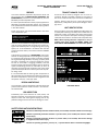 3
3
-
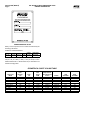 4
4
-
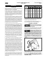 5
5
-
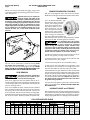 6
6
-
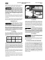 7
7
-
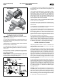 8
8
-
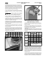 9
9
-
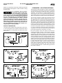 10
10
-
 11
11
-
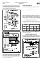 12
12
-
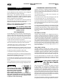 13
13
-
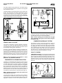 14
14
-
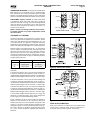 15
15
-
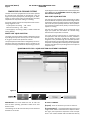 16
16
-
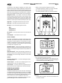 17
17
-
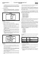 18
18
-
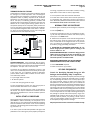 19
19
-
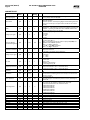 20
20
-
 21
21
-
 22
22
-
 23
23
-
 24
24
-
 25
25
-
 26
26
-
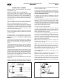 27
27
-
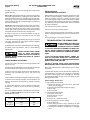 28
28
-
 29
29
-
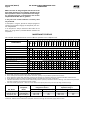 30
30
-
 31
31
-
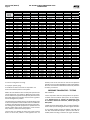 32
32
-
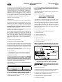 33
33
-
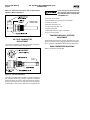 34
34
-
 35
35
-
 36
36
-
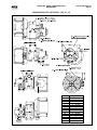 37
37
-
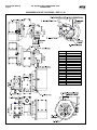 38
38
-
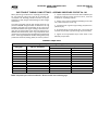 39
39
-
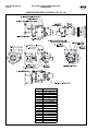 40
40
-
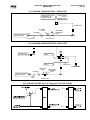 41
41
-
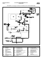 42
42
-
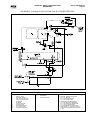 43
43
-
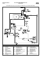 44
44
-
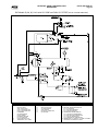 45
45
-
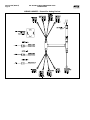 46
46
-
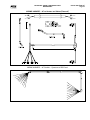 47
47
-
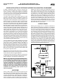 48
48
-
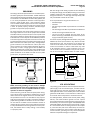 49
49
-
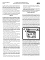 50
50
-
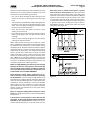 51
51
-
 52
52
-
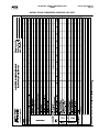 53
53
-
 54
54
-
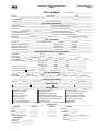 55
55
-
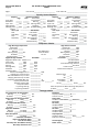 56
56
-
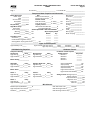 57
57
-
 58
58
-
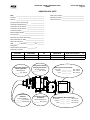 59
59
-
 60
60
-
 61
61
-
 62
62
-
 63
63
-
 64
64


Frick RXF Redesign Installation Operation and Maintenance Guide
- Type
- Installation Operation and Maintenance Guide
Ask a question and I''ll find the answer in the document
Finding information in a document is now easier with AI
Related papers
-
 Frick RXF Installation Operation and Maintenance Guide
-
 Frick RXF Installation Operation and Maintenance Guide
-
 Frick RXF Installation Operation and Maintenance Guide
-
 Frick RXF Installation Operation and Maintenance Guide
-
 Frick RXF Redesign Installation Operation and Maintenance Guide
-
 Frick RXF Redesign Installation Operation and Maintenance Guide
-
 Frick RXF Redesign Installation Operation and Maintenance Guide
-
 Frick RXF Installation Operation and Maintenance Guide
-
 Frick RXF Installation Operation and Maintenance Guide
-
 Frick RXF Installation Operation and Maintenance Guide


