Page is loading ...

IMPORTANT: Keep these user instructions for reference.
Macurco™ DMK-1
Duct Mount Kit
Installation Guide

DMK-1 Installation Guide
REV – 1.0 [34-2900-0065-9 ] 2 | P a g e
1 General Safety Information ...................................................................................................................................... 3
1.1 Warnings ........................................................................................................................................................... 3
2 Application ................................................................................................................................................................ 4
2.1 Features ............................................................................................................................................................. 4
2.2 Specifications..................................................................................................................................................... 4
3 Installation Instructions............................................................................................................................................ 5
3.1 Location ............................................................................................................................................................. 5
3.2 Assembly Instructions ....................................................................................................................................... 5
3.3 Installation ......................................................................................................................................................... 7
3.4 Pressure Differential Testing ............................................................................................................................. 8
3.5 Mounting the Detector ..................................................................................................................................... 9
4 Maintenance ........................................................................................................................................................... 10
5 Appendix ................................................................................................................................................................. 11
6 Macurco Gas Detection Product limited warranty ............................................................................................... 12

DMK-1 Installation Guide
REV – 1.0 [34-2900-0065-9 ] 3 | P a g e
1 General Safety Information
1.1 Warnings
WARNING
Each person using this equipment must read and understand the information in this
user manual before use. Use of this equipment by untrained or unqualified persons or
use that is not in accordance with this user manual, may adversely affect product
performance.
Use only for monitoring the gas which the sensor and monitor is designed to detect.
Failure to do so may result in exposures to gases not detectable and cause serious
injury or death. For proper use, see supervisor or user manual, or contact Technical
Support at 1-844-325-3050.
This detector helps monitor for the presence and concentration level of a certain
specified airborne gas. Misuse may produce an inaccurate reading, which means that
higher levels of the gas being monitored may be present and could result in
overexposure and cause serious injury or death. For proper use, see supervisor or User
manual, or contact Technical Support at 1-844-325-3050.
The DMK-1 is specifically designed for use with Macurco gas detectors. After the DMK-
1 is installed and tested, refer to the appropriate Macurco gas detectors User manual
for installing and testing the detector to be installed. For additional support, contact
Technical Support at 1-844-325-3050.
During installation, a Pressure Differential test must be performed on the DMK-1 to
ensure proper installation and function of the device.

DMK-1 Installation Guide
REV – 1.0 [34-2900-0065-9 ] 4 | P a g e
2 Application
The Macurco DMK-1 is an air tight enclosure that provides a means to mount any Macurco gas detector to an air
duct. By duct mounting a Macurco gas detector it can monitor the air inside of the duct and provide early detection
of carbon monoxide or other gases moving through the HVAC system. The DMK-1 used with Macurco gas detectors
can provide automatic control to prevent recirculation of these gases into additional areas by the air handling
systems, fans and blowers in commercial and residential applications.
2.1 Features
• Provides detection and monitoring of gas concentrations in ventilation ducts
• Clear cover allows view of detector, displays and status lights
• PC – Polycarbonate housing
• Injection Molding Grade, Flame Retardant, UV Stabilized
Included with the DMK-1
• Enclosure with cover, gasket and screws
• Standoffs - hex aluminum
• Machine screws - Phillips head
• Strain relief/seal for wiring exit hole
• Nut for strain relief
• Sheet metal mounting screws
• Foam compression seals
• A full-size drill hole position template
Not included with the DMK-1
• Macurco Gas Detector
• Input sampling tube: available in various lengths from HVAC and Security distributors
• Single gang type detectors, CM-E1 and GD-2B, will need a 4” single gang mud-ring
2.2 Specifications
• Size: 6 1/4 x 6 1/4 x 3 1/2 inches (15.9 x 15.9 x 8.9 cm)
• Exhaust Tube: EMT, 1/2” (1.3 cm) diameter 6 1/2” length (16.5 cm)
• Setscrew Adapters: EMT, 1/2” (1.3 cm)
• Shipping Weight: 1.5 pounds (0.68 kg)

DMK-1 Installation Guide
REV – 1.0 [34-2900-0065-9 ] 5 | P a g e
3 Installation Instructions
3.1 Location
The DMK-1 and gas detector should be mounted on air ducts downstream from any duct openings, deflection plates,
sharp bends or branch connections. If it is not physically possible to locate the detector accordingly, it is best
positioned as far from the opening, bend or deflection plates as possible. Supply duct gas detector installation
should be downstream of fans, filters, chillers, heaters and humidifiers. Return duct gas detectors should be located
at return air opening within the compartment, where the air exits each compartment or in the duct system before
air enters the return air system common to more than one compartment.
3.2 Assembly Instructions
3.2.1 Remove the clear cover from the enclosure and remove the contents.
3.2.2 Insert conduit setscrew adapters into the two large holes in the back of the enclosure. Install the nuts for
setscrew adapters inside the enclosure and tighten.
3.2.3 Insert four (4) machine screws through the back of enclosure. Secure them with the four (4) standoffs inside
the enclosure and tighten.
3.2.4 Insert the Strain Relief/Seal into the remaining large hole on the bottom of the enclosure. Install the nut for
strain relief/seal inside the enclosure and tighten

DMK-1 Installation Guide
REV – 1.0 [34-2900-0065-9 ] 6 | P a g e
3.2.5 Remove the adhesive cover on one side of foam seals. Place them over the conduit setscrew adapters on
the outside of the enclosure as pictured.
3.2.6 Install the exhaust tube into the “downstream” setscrew adapter with the open end of the 45-degree cut
facing downstream.
3.2.7 Install the appropriately sized sampling tube (not provided) into the “upstream” setscrew adapter with the
ports facing upstream.
Important:
• The sampling tube MUST extend at least 2/3 into the width of the duct.

DMK-1 Installation Guide
REV – 1.0 [34-2900-0065-9 ] 7 | P a g e
• The end of the sampling tube that is in the duct must be closed or capped to ensure appropriate air flow
through the DMK-1 and to the detector.
• Tube support is required in all instances where the tube length is greater than three feet.
• The sampling and exhaust tubes must be installed in the proper orientation to ensure appropriate air flow
through the DMK-1 and to the detector.
3.3 Installation
3.3.1 Place the enclosed template on the duct at the desired mounting spot. Mark the six (6) holes to be drilled.
3.3.2 Drill two (2) large and four (4) small holes in the duct you want to mount the unit on using the template
provided. The two large holes (1 ½”) are for the sampling and exhaust tubes. The four small holes (1/16”)
are starter holes for the sheet metal mounting screws. Ensure that the intake and exhaust tube holes are
large enough to allow all the setscrew adapters to fit.
3.3.3 Place each of the four (4) sheet metal mounting screws in one of the shouldered holes at the corners of the
enclosure base.
3.3.4 Place the enclosure onto the duct to test for proper hole alignment. Place the unit against the duct in its
intended position.
3.3.5 Fasten the enclosure to the duct by installing the four (4) sheet metal screws.

DMK-1 Installation Guide
REV – 1.0 [34-2900-0065-9 ] 8 | P a g e
3.4 Pressure Differential Testing
WARNING
A pressure differential test is required to ensure proper operation of the DMK-1. This
test requires the use of an Analog or Digital Manometer. The differential pressure
should measure at least 0.01 inches of water and no more than 1.11 inches of water.
3.4.1 Follow the manometer instruction manual for proper setup
3.4.2 Verify and note the current manometer reading and adjust if necessary
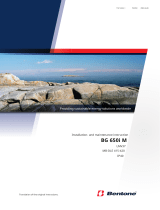
3.4.3 With the DMK-1 cover removed, plug the manometer, positive (+) end or HIGH end into the sampling tube
end and the Negative (-) or LOW end into the exhaust tube end
3.4.4 To verify sufficient pressure differential, turn the air handler on and use the manometer to measure the
differential pressure between the two sampling tubes. The differential pressure should measure at least
0.01 inches of water and no more than 1.11 inches of water.
Check the following if the differential pressure measurements are outside of the specified range:
• Ensure that the air velocity in the duct is within the specified range. If necessary, use a velocity meter to
check the air velocity in the duct.
• Verify the sampling tube is installed with the air inlet holes facing into the airflow. Note that the
sampling tube and exhaust tube can be mounted in either housing connection if the exhaust tube is
mounted downstream from the sampling tube.
• Verify that the end cap is installed at the end of the sampling tube.
• Verify that the sampling tube extends to a minimum of 2/3 duct width.
• Verify that the DMK-1 is properly sealed to the duct.
Negative (-)
or LOW
Positive (+)
or HIGH
Negative (-)
Positive (+)

DMK-1 Installation Guide
REV – 1.0 [34-2900-0065-9 ] 9 | P a g e
3.5 Mounting the Detector
3.5.1 Run the wiring through the strain relief. Twist the outer cap of the strain relief clockwise to compress the
gasket material around the wiring.
3.5.2 Connect the wiring according to the instructions provided for the detector.
3.5.3 Install the gas detector onto the top of the four (4) standoffs. Secure it in place using the four (4) remaining
machine screws.
Important:
• Be sure that there is a good seal between the DMK-1 and the duct surface around the sampling and exhaust
tubes to ensure appropriate air flow through the DMK-1 and to the detector.
3.5.4 Test the installed detector as described in the detector’s User Manual.
3.5.5 Replace the cover and tighten the cover screws.

DMK-1 Installation Guide
REV – 1.0 [34-2900-0065-9 ] 10 | P a g e
4 Maintenance
The Macurco DMK-1 requires minimal maintenance. Ensure that the vented sampling inlets remain unobstructed
and is free of debris to maintain good air flow through the enclosure. Please refer to the specific detector User
Instructions for maintenance requirements, installation information and warnings.
4.1.1 Cleaning of the external surfaces is best carried out using a damp cloth with a mild detergent or soap. Use a
vacuum cleaner with soft brush to remove dust or contamination under the cover and to clean the vented
sampling inlets.
WARNING
Do not blow out the sensor with compressed air. Using compressed air may damage
the sensor causing the sensor to not respond to the target gas.
WARNING
High voltage terminals (120/240 VAC) are located within the Macurco 12 series
detectors, presenting a hazard to service technicians. Only qualified technicians should
open the detector case and service the internal circuits. Ensure power is de-energized
from the detector relays prior to servicing the unit. Failure to do so may result in
electrical shock.
CAUTION
Avoid using caustic, abrasive cleaners and other organic solvents. These materials may
scratch surfaces and permanently damage the display window, labels, sensor or
instrument case.

DMK-1 Installation Guide
REV – 1.0 [34-2900-0065-9 ] 11 | P a g e
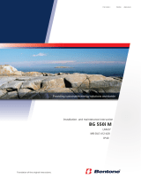
5 Appendix
DMK-1 Drill Hole Position Template
External Dimensions: 6.299 x 6.299 x 3.543 in.

DMK-1 Installation Guide
REV – 1.0 [34-2900-0065-9 ] 12 | P a g e
6 Macurco Gas Detection Product limited warranty
Macurco warrants the DMK-1 Duct Mount Kit will be free from defective materials and workmanship for a period of two (2) years
from the date of manufacture, provided it is maintained and used in accordance with Macurco instructions and/or
recommendations. If any component becomes defective during the warranty period, it will be replaced or repaired free of charge, if
the unit is returned in accordance with the instructions below. This warranty does not apply to units that have been altered or had
repair attempted, or that have been subjected to abuse, accidental or otherwise. The above warranty is in lieu of all other express
warranties, obligations or liabilities. THE IMPLIED WARRANTIES OF MERCHANTABILITY AND FITNESS FOR PARTICULAR
PURPOSE ARE LIMITED TO A PERIOD OF TWO (2) YEARS FROM THE PURCHASE DATE. Macurco shall not be liable for any
incidental or consequential damages for breach of this or any other warranty, express or implied, arising out of or related to the use
of said gas detector. The manufacturer or its agent’s liability shall be limited to replacement or repair as set forth above. Buyer’s
sole and exclusive remedies are the return of the goods and repayment of the price, or repair and replacement of non-conforming
goods or parts.
Macurco Gas Detection
3601 N. St. Paul Avenue
Sioux Falls, SD 57104
Technical Support Contact Information
Phone: 1-844-325-3050
Fax: 1-605-951-9616
Email: [email protected]
Website: www.support.macurco.com
General Contact Information
Phone : 1-877-367-7891
Fax : 1-605-951-9616
Email : [email protected]
Website: www.macurco.com
REV – 1.0
Issue Date: 8-16-2019
Document No: 34-2900-0065-9
© Aerionics 2019. All rights reserved.
Macurco is a trademark of Aerionics, Inc.
/