
IMPORTANT: These User Instructions are to be provided to the homeowner/end user upon product
installation. Each person installing or using this equipment must read and understand the information
in these User Instructions before use. Installation of this equipment by untrained or unqualified
persons, or use that is not in accordance with these User Instructions may adversely affect product
performance and result in sickness or death. For proper use see User Instructions or call Macurco
Technical Service.
Macurco™ IAQ
Carbon Dioxide Detector
User Instructions

Macurco IAQ Carbon Dioxide Detector
REV – 1.0 [34-2900-0030-3] 2 | P a g e
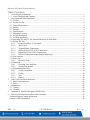
Table of Contents
1 General Safety Information........................................................................................................................3
1.1 List of Warnings and Cautions ..............................................................................................................3
2 Use Instructions and Limitations ...............................................................................................................3
2.1 Use For ...................................................................................................................................................3
2.2 Do Not Use For ......................................................................................................................................4
2.3 General Description ...............................................................................................................................4
2.4 Models....................................................................................................................................................4
2.5 Features ..................................................................................................................................................4
2.6 Specifications .........................................................................................................................................4
2.7 Mounting Location.................................................................................................................................6
2.8 In-Wall Installation ................................................................................................................................7
2.9 On-Wall Installation...............................................................................................................................8
2.10 Attaching The IAQ To The External Enclosure Or Wall Plate .............................................................9
2.11 Wiring The IAQ ...................................................................................................................................11
2.11.1 Connecting Wires To Terminals ..............................................................................................11
2.11.2 Wire Types ...............................................................................................................................13
2.11.3 Terminal Block Connections ...................................................................................................14
2.11.4 Analog (IAQ-CO2-2-A-W) Connections ................................................................................14
2.11.5 Digital (IAQ-CO2-2-D-2) Connections ...................................................................................15
2.11.6 RS-485 Termination Jumper (Digital IAQ Only) ....................................................................17
2.12 User Interface .......................................................................................................................................18
2.13 Power Up .............................................................................................................................................18
2.13.1 Power-Up Test .........................................................................................................................19
2.14 Operation..............................................................................................................................................19
2.14.1 Checking Time And Date ........................................................................................................20
2.14.2 Setting Time & Date ................................................................................................................20
2.15 Programming The IAQ ........................................................................................................................23
2.15.1 Config. Navigation ...................................................................................................................24
2.15.2 Config. .....................................................................................................................................26
2.15.3 Test ...........................................................................................................................................39
2.15.4 History......................................................................................................................................41
3 End Of Life And Error Indicators ............................................................................................................43
3.1 End-Of-Life Indicator ..........................................................................................................................43
3.2 Errors....................................................................................................................................................43
4 Maintenance .............................................................................................................................................45
4.1 Testing..................................................................................................................................................45
4.2 Cleaning ...............................................................................................................................................45
5 Appendix A –Detailed Navigation Of The IAQ ......................................................................................46
6 Macurco Gas Detection Product limited warranty...................................................................................59
Technical Support Contact Information .......................................................................................................59
General Contact Information ........................................................................................................................59

Macurco IAQ Carbon Dioxide Detector
REV – 1.0 [34-2900-0030-3] 3 | P a g e
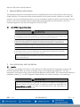
1 General Safety Information
The following instructions are intended to serve as a guideline for the use of the Macurco IAQ Indoor Air
Quality Detector. This manual will refer to these devices as IAQ unless content is specific to a model. This
manual is not to be considered all-inclusive, nor is it intended to replace the policy and procedures for your
facility. If you have any doubts about the applicability of the equipment to your situation, consult an
industrial hygienist or call Technical Support at 1-844-325-3050.
1.1 List of Warnings and Cautions
WARNING
Each person using this equipment must read and understand the information in this User
manual before use. Use of this equipment by untrained or unqualified persons or use that is not
in accordance with this user manual, may adversely affect product performance.
Use only for monitoring the gas which the sensor and monitor is designed to detect. Failure to
do so may result in exposures to gases not detectable and cause serious injury or death. For
proper use, see supervisor or user manual, or contact Technical Support at 1-844-325-3050.
IAQ may not function effectively below 32° F (0° C) or above 122° F (50° C). Using the equipment
outside of this temperature range may adversely affect product.
Immediately exit any environment that causes an alarm condition on the sensor.
Do not disassemble unit or attempt to repair or modify any component of this instrument. This
instrument contains no user serviceable parts, and substitution of components may adversely
affect product performance and void product warranty.
Only qualified technicians should open the detector case and service the internal circuits. Ensure
power is de-energized from the detector relays prior to servicing the unit. Failure to do so may
result in electrical shock.
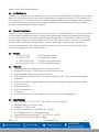
2 Use Instructions and Limitations
2.1 Use For
The IAQ is a low-voltage (12-24 VAC or VDC) detector of carbon dioxide (CO2) designed to monitor and
maintain adequate indoor air quality, aid energy savings, and mitigate stale, polluted air. The IAQ is
designed for connection to fans and to building management systems (BMS). This carbon dioxide detector is
designed to detect CO2. It is NOT designed to detect smoke, fire, carbon monoxide, or any other gas.
WARNING
Use only for monitoring the gas that the sensor and detector are designed to
monitor. Failure to do so may result in exposures to gases not detectable and
cause sickness or death. For proper use, see supervisor or User Instructions, or
call Macurco Technical Service.

Macurco IAQ Carbon Dioxide Detector
REV – 1.0 [34-2900-0030-3] 4 | P a g e
2.2 Do Not Use For
The IAQ is not intended for use in hazardous locations or industrial applications such as refineries, chemical
plants, etc. Do not mount the IAQ where the normal ambient temperature is below 32° F or exceeds 122° F
(0° C or above 50° C). The IAQ mounts on a type 2S (single-gang) electrical box supplied by the contractor or
it can be wall-mounted using an enclosure supplied by Macurco. Do not install the IAQ inside another
enclosure unless it has good air flow through it.
2.3 General Description
The Macurco IAQ product family ensures you “Know Your Air” in indoor applications. The IAQ is an essential
tool for maintaining adequate indoor air quality, aiding with energy savings and mitigating stale, polluted
air. The family of products accurately monitors Carbon Dioxide (CO2). The detector has options for either
analog or digital outputs to control ventilation as CO2 and VOC values increase. There are various model
options based on the need of the application. Common applications include but are not limited to
classrooms, gymnasiums, malls, theaters, airports, concert venues, convention halls, office buildings,
universities, shopping centers, and auditoriums.
2.4 Models
IAQ-CO2-A-W CO2 Analog Wall Mount
IAQ-CO2-D-W CO2 Digital Wall Mount
IAQ-CO2/VOC-A-W CO2/VOC Analog Wall Mount
IAQ-CO2/VOC-D-W CO2/VOC Digital Wall Mount
2.5 Features
Easy installation to a single-gang box or on-wall enclosure
Aesthetically pleasing — flush-mount or surface-mount options
User-selectable settings via two-button interface
0.5A configurable normally open or normally closed (N.O. or N.C.) dry-contact relay to engage
ventilation
Versions with analog or digital output to send values to building management systems (BMS)
Occupancy mode
Adjustable setpoints
End-of-life notification
LCD display
Last 30 days’ historical events: Highest value, lowest value, and average per day
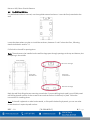
2.6 Specifications
Size: 3.125” (H) x 5.125” (L) x 1.75” (W), 80 mm x 127mm x 44.5mm
Shipping Weight: 1 pound (0.45 kg)
Voltage: 12-24 VAC or VDC
Current (normal/alarm): 15mA/35mA @ 12-24VDC
CO2 Range/Resolution: 0-2,000 ppm/10 ppm
Operating Temperature Range: 32°F to 122°F (0°C to 50°C)
Display: LCD 2x8 characters with backlight

Macurco IAQ Carbon Dioxide Detector
REV – 1.0 [34-2900-0030-3] 5 | P a g e
Analog Current Loop: 4-20mA
Mounting: flush to single-gang box or surface mount
Relay: 0.5A Control Relay with user-adjustable settings
Warranty: Two-Year Limited Warranty
Life Expectancy: 10 Years
Installation & Operation Instructions
The following instructions are intended to serve as a guideline for the use of the Macurco IAQ Carbon
Dioxide Detector. It is not to be considered all-inclusive, nor is it intended to replace the policies and
procedures for each facility.
WARNING
This detector helps monitor the presence and concentration level of certain
specified airborne gases. Misuse may produce an inaccurate reading, which
means that higher levels of the gas being monitored may be present and could
result in overexposure and cause sickness or death. For proper use, see supervisor
or User Instructions, or call Macurco Technical Service.
WARNING
This product is intended for use in ordinary indoor locations such as:
Homes
Schools and universities
Conference rooms
Theaters and concert venues
Airports
Museums
Convention halls
Office buildings
Malls
The IAQ is not designed to measure compliance with Occupational Safety and
Health Administration (OSHA) commercial or industrial standards.
Note: The IAQ performs automatic background calibration. Therefore, does not require field calibration.

Macurco IAQ Carbon Dioxide Detector
REV – 1.0 [34-2900-0030-3] 6 | P a g e
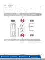
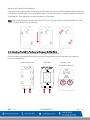
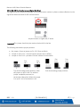
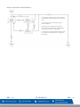
2.7 Mounting Location
Carbon dioxide (CO2) can accumulate inside buildings, especially those that are designed to reduce drafts
such as in cold climates, but also in homes, schools, offices, etc., where buildings are sealed to maintain air
conditioning in warm climates. Carbon dioxide at levels that are unusually high indoors may cause
occupants to grow drowsy, complain of eye irritation, to get headaches, or to function at lower activity
levels. The IAQ detects CO2 and can control exhaust fans to bring in fresh air.
For best operation, mount the IAQ 4´ to 6´ (1.2m to 1.8m) off the floor. In addition, do not mount the IAQ
within 10´ (3m) of an air outlet, and do not place the IAQ directly above or below an air outlet, regardless of
distance. Also: Do not mount the IAQ within 10’ (3m) of a door or window that can be opened. Drafts can
affect readings.
Do NOT mount the unit in a garage. Do NOT mount the IAQ where the normal ambient temperature is
below 32°F (0°C) or exceeds 122°F (50°C), or within 5 feet (1.5 meters) of a cooking or heating appliance.
4
’
to 6
’
(1.2m to 1.8m)
>10’ (3m) >10’ (3m)

Macurco IAQ Carbon Dioxide Detector
REV – 1.0 [34-2900-0030-3] 7 | P a g e
2.8 In-Wall Installation
The IAQ should be 4´ to 6´ (1.2m to 1.8m) off the floor. (Refer to section 2.7 for more details regarding
installation locations and clearances.) Preferably, an in-wall single-gang (2S) electrical box should be
installed vertically at each location so that the IAQ can be firmly mounted and the display easily readable.
(Alternatively, an external enclosure can be used for mounting on the wall’s surface. See instructions in
section 2.9.)
Important! Before starting, ensure all local ordinances and codes are followed.
Run power and communication cables to each electrical box before performing installation of the
IAQ detectors.
Solid-core wire is preferred over stranded wire for easier connection to the IAQ.
Make sure that about 6” to 8” (15cm to 20cm) of wire protrudes from the wall to make wiring the
IAQ easier.
Note: For easier installation, run the wires through the box before installing the mounting plate.
Align the mounting plate’s two screw holes over the threaded screw holes in the box.
Important! Make sure the arrow that indicates “UP” is at the top.
Insert the two screws and tighten them with a screwdriver. Do not overtighten.
Align mounting
plate’s two screw
holes with the
threaded screw
holes in the
electrical box.

Macurco IAQ Carbon Dioxide Detector
REV – 1.0 [34-2900-0030-3] 8 | P a g e
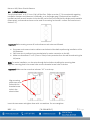
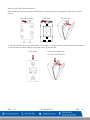
2.9 On-Wall Installation
If in-wall electrical box is not used, use the supplied external enclosure. It must be firmly attached to the
wall.
Locate the place where you plan to install the enclosure, between 4’ and 6’ above the floor, following
details described in section 3.1.
Drill a hole in the wall for passing wires.
Note: The enclosure to be installed on the wall has large pass-through openings at the top and bottom, but
no opening in the middle.
Mark the wall for drilling the two mounting screw holes. If you are drilling into drywall, you will likely need
self-drilling drywall anchors for the screws to ensure that the box is held firmly in place. Follow the
instructions for installing those.
Note: If the wall is plywood or other hard material, or if drywall is backed by plywood, you can use other
screws that don’t require drywall anchors.
2” (51mm)
2.25” (57mm)
Rear View
Of Enclosure
Wire Pass-Through
Wire Pass-Through
Front View
Of Enclosure

Macurco IAQ Carbon Dioxide Detector
REV – 1.0 [34-2900-0030-3] 9 | P a g e
Pass the wires through the back of the box and then attach the box to the wall by tightening the screws only
until the box is held loosely. Do not fully tighten them. Press the box down so that the screws are at the top
of the keyhole. Then tighten the screws until there is no free play.
Note: Screw shaft diameters should be less than 5/32” (4mm). Screw heads should be between 1/4” and
17/64” (6.35mm and 6.7mm) in diameter.
2.10 Attaching The IAQ To The External Enclosure Or Wall Plate
The IAQ attaches to the external enclosure or wall plate in the same way.
Insert the tabs at the bottom of the IAQ into the two mating points on the lower part of the external
enclosure or wall plate:
External Enclosure Wall Plate Bottom View
(External Enclosure)
VERTICAL
MOUNT
UP

Macurco IAQ Carbon Dioxide Detector
REV – 1.0 [34-2900-0030-3] 10 | P a g e
Next, tilt the IAQ so that the capture tab at the top is inserted into the mating point. Make sure it is held
secure.
External Enclosure Wall Plate Tilt Into Place
To release the IAQ from its mounted position, press down on the top center of either the external enclosure
or the wall plate and while holding your finger down, tilt out the IAQ.
Press Down
Continue Pressing Down
And Tilt Front Panel Out
VERTICAL
MOUNT
UP

Macurco IAQ Carbon Dioxide Detector
REV – 1.0 [34-2900-0030-3] 11 | P a g e
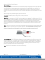
2.11 Wiring The IAQ
The IAQ is designed for simple wiring. All connections are at the terminal block, which is on the main PC
board.
The terminal block is located on the main PC board as shown:
Analog IAQ Main PCB Digital IAQ Main PCB
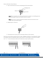
2.11.1 Connecting Wires To Terminals
1. Strip each wire back 1/4 in. (6.5 mm), exposing bare wire.
2. Press in on a release tab with the tip of a ballpoint pen (or similar tool).
Ballpoint Pen
Release Tabs

Macurco IAQ Carbon Dioxide Detector
REV – 1.0 [34-2900-0030-3] 12 | P a g e
3. Fully insert the bare wire into the corresponding slot of the terminal block.
Note: When inserting the wire, make sure that the wire’s insulation is not inhibiting the wire
from contacting the contact point inside the terminal connector.
Note: When the wire is properly stripped and inserted in the terminal connector, there
should not be any bare wire exposed.
4. Release the pen or other tool.
5. Check that the wire is secure and cannot be easily pulled out of the connector.
Not all slots are used when wiring the IAQ into a system. Regardless of whether it is an Analog IAQ or Digital
IAQ, however, both are provided with power via slots 9 and 10. The IAQ accepts 12-30 volts DC, and either
the “+” or “-” can be connected to either slot. The IAQ does not require specific polarity.
Wire Slots
Ballpoint Pen
Release Tabs
Wire

Macurco IAQ Carbon Dioxide Detector
REV – 1.0 [34-2900-0030-3] 13 | P a g e
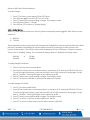
2.11.2 Wire Types
All wiring is done via the terminal block. The terminal block accepts wire gauges from 14 to 28 AWG. Solid
wires of moderate or heavier gauge can be pushed directly into the appropriate slots in the block. For
stranded wires, you must manually open the spring-loaded contact with the release tabs during wire
insertion or have ferrules on the ends of the wires. Manually opening the contact also applies to thin solid
wires.
When wiring the IAQ, the following wire types should be used:
Analog IAQ. 18 AWG for power, analog circuit, and relay connection.
Digital IAQ. For the power wire, 18 AWG 2-conductor signal wire is suggested. For Modbus wiring, 22 to 24
AWG is suggested. For best performance, use shielded 3-conductor wire with one twisted pair that provides
a pair for signal (A & B), common (COM) and shield ground. The shield should be connected on each
detector at the ground terminal along with the drain wire and connected to a ground terminal or chassis
only at one end of the bus. An RS485 Modbus must use a balanced pair (for A & B) and a third wire (for
Common).
Note: A drain wire is the bare, stranded wire interleaved with the wrapping foil inside shielded cables.
This wire plays an important part in the cable's operation. "The shield should be connected on each
detector at the ground terminal along with the drain wire and connected to a ground terminal"
For RS-485 Modbus. For RS-485 Modbus configuration, the wire’s gauge must be sufficient to permit the
maximum length (3,281’, or 1,000m). AWG 24 is always sufficient for carrying Modbus data. Category 5
cables may be employed for RS-485 Modbus, to a maximum length of 1968.5’ (600m). For the balanced
pairs used in an RS-485 system, wire with a characteristic impedance greater than 100 ohms may be
preferred, especially for baud rates of 19200 and higher.
Note: Relay functions and Modbus can be used simultaneously.
Signal Wires
Insulation
Drain Wire
Shield

Macurco IAQ Carbon Dioxide Detector
REV – 1.0 [34-2900-0030-3] 14 | P a g e
2.11.3 Terminal Block Connections
All connections are made at the terminal block, located on the main PC board. Follow the instructions in
Section 2.11 for proper installation.
Note: Before inserting a wire into a slot in the terminal block, strip insulation back 1/4" (6.5 mm).
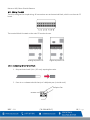
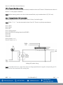
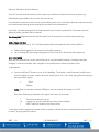
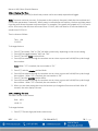
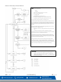
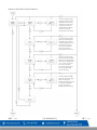
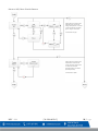
2.11.4 Analog (IAQ-CO2-A-W) Connections
The following shows the functions of each of the 10 slots, from left to right.
Note: Either “+” or “–” can be connected to slots 9 and 10. There is no polarity requirement.
Slot 1: Relay
Slot 2: Relay
Slot 3: NA
Slot 4: Analog Output
Slot 5: ISO GND (for analog channel and RS485)
Slot 6: NA
Slot 7: NA
Slot 8: NA
Slot 9: Power (+ or –)
Slot 10: Power (+ or –)
Analog IAQ system wiring.
Note: A variable drive fan is a type of fan that can change speed based on signals corresponding to CO2
levels and can be connected to the analog loop.
Fan

Macurco IAQ Carbon Dioxide Detector
REV – 1.0 [34-2900-0030-3] 15 | P a g e
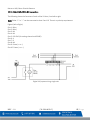
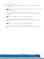
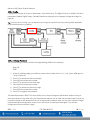
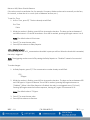
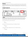
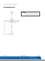
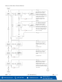
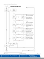
2.11.5 Digital (IAQ-CO2-D-W) Connections
The following shows the functions of each of the 10 slots, from left to right.
Note: Either “+” or “–” can be connected to slots 9 and 10. There is no polarity requirement.
Digital (Left to Right):
Slot 1: Relay
Slot 2: Relay
Slot 3: NA
Slot 4: NA
Slot 5: ISO GND (for analog channel and RS485)
Slot 6: A
Slot 7: B
Slot 8: NA
Slot 9: Power (+ or –)
Slot 10: Power (+ or –)
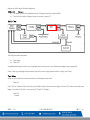
Digital IAQ system wiring, single unit.

Macurco IAQ Carbon Dioxide Detector
REV – 1.0 [34-2900-0030-3] 16 | P a g e
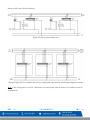
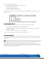
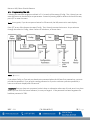
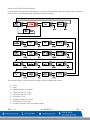
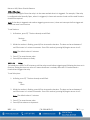
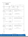
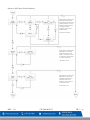
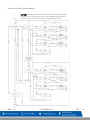
Digital IAQ wiring with multiple units.
Multiple Digital IAQs in a Modbus daisy-chain configuration connected to a building management system.
Note: In this configuration, up to 247 addresses can be employed. Refer to section 0 for details on how to
set addresses.

Macurco IAQ Carbon Dioxide Detector
REV – 1.0 [34-2900-0030-3] 17 | P a g e
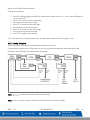
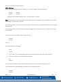
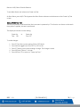
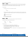
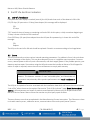
2.11.6 RS-485 Termination Jumper (Digital IAQ Only)
The Digital IAQ has a jumper for placing a 120-ohm termination resistor in place to reduce reflections in the
signal lines when used with RS-485 communication.
Jumper location on Digital IAQ PC board.
Important! This jumper should only be used on the last IAQ in the line.
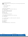
The following describe the jumper positions:
No jumper = Same as jumper on Pin 1 & 2 (has no effect)
Jumper on Pins 1 & 2 = Used to hold the jumper (has no effect)
Jumper on Pins 2 & 3 = provides 120-ohm resistor for termination
Top view showing jumper positions. With
the jumper on pins 1 and 2 or with the
jumper completely removed, no
termination takes place. When the jumper
is on pins 2 and 3, termination is set.
End view showing jumper positions.
Pins
1 & 2
Pins
2 & 3
Pins
1 & 2
Pins
2 & 3

Macurco IAQ Carbon Dioxide Detector
REV – 1.0 [34-2900-0030-3] 18 | P a g e
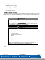
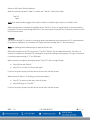
2.12 User Interface
The IAQ has two buttons and a two-line LCD. The buttons are labeled:
M/N = Menu/Next
E/T = Enter/Test
The display indicates settings and functions and has adjustable contrast, backlighting level, and backlighting
time. Refer to 0 for details on display settings.
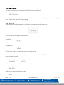
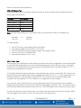
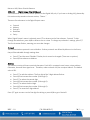
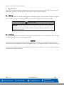
2.13 Power Up
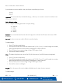
When the IAQ is initially powered up, the display illuminates and briefly shows this:
Then it shows this message for five seconds:
Analog IAQ:
IAQ_A
VX.XX.XX
Or Digital IAQ:
IAQ_D
VX.XX.XX
In both cases, X.XX.XX indicates the current firmware version.
If the date and time were set previously, they are shown in this format (AM/PM and
hours/minutes/seconds):
Time AM or Time PM
HH:MM:SS 11:02:22
Until the date is set, press M/N to view the date that has been set in the system:
Date MDY
MM-DD-YY
Until the date is set, press M/N and see:
Return

Macurco IAQ Carbon Dioxide Detector
REV – 1.0 [34-2900-0030-3] 19 | P a g e
Press E/T to enter Normal mode (or enter a warm-up countdown if within 60 seconds of power-up).
Alternatively, press M/N to return to the Time Set screen.
If no buttons are pressed in the first five minutes after power-up, the IAQ enters Normal mode and uses the
last time and date settings as the starting time and date for the new session.
If the time- and date-setting menu has been entered but no button is pressed for 30 seconds, the main
display is shown (normal mode is entered).
For Analog IAQ: Registration levels will be output from 15 seconds to 21 seconds after power-up.
2.13.1 Power-Up Test
If the power-up test is set to “On,” the following take place (the power-up test is set by default):
Relay will be engaged for 10 seconds shortly after power-up.
For an Analog IAQ, the analog output goes to 16mA from 40 to 60 seconds after power-up.
2.14 Operation
With the IAQ powered up, it starts monitoring the air using the default settings. If settings have been
changed, it uses those instead. Basic navigation is simple because it follows consistent rules.
To get started:
Press the M/N or E/T button to turn on the backlight. The display is now illuminated, and the main
(normal) display is shown. It tells you the air quality (Good, Fair, Poor, Bad), along with the reading in
parts per million (ppm):
L Good
790ppm
Note: If the concentration exceeds 2300ppm, then the display will change to “>2310”.
One of the following is displayed in the upper left corner of the screen:
T The time and date are not set
W Logging has not yet completed one day of data collection
L Data is ready for review in the History menu
To the right of that is a general condition of the air quality, and below that is a reading of the measured CO2
in the air, in ppm (parts per million).

Macurco IAQ Carbon Dioxide Detector
REV – 1.0 [34-2900-0030-3] 20 | P a g e
1. Press M/N to advance from the main screen to Config.
2. Press M/N to advance to Test.
3. Press M/N to advance to History.
4. Press M/N to return to the main display.
At any of the screens (Config., Test, History), if you do not press M/N again within 30 seconds, the main
display is shown.
2.14.1 Checking Time And Date
The time and date set in the IAQ’s internal clock can be accessed from the main display.
1. At the main display, press M/N or E/T to illuminate the display.
2. Press E/T from the main display to enter the Date/Time screen. Time and date are shown in the
formats set in the IAQ.
3. Press E/T to exit Time/Date and return to the main display.
If you do not press E/T again within 30 seconds, the main display is shown.
2.14.2 Setting Time & Date
Following the first power-up of the system with the IAQ, set the time and date. Also, to ensure maximum
accuracy if the power to the system is disrupted, check the time and date and correct their parameters if
necessary.
Note: When power is restored after a disruption, the time and date restart from the point where the power
was interrupted. For example, if the power is disrupted at 12:14:10 and is off for 10 minutes, then the time
will resume from 12:14:10, but it will then be 10 minutes behind the actual time of 12:24:10.
the time and date restart from the point where the power was interrupted. For example, if the power is
disrupted at 12:14:10 and is off for 10 minutes, then the time will resume from 12:14:10, but it will then be
10 minutes behind the actual time of 12:24:10.
Page is loading ...
Page is loading ...
Page is loading ...
Page is loading ...
Page is loading ...
Page is loading ...
Page is loading ...
Page is loading ...
Page is loading ...
Page is loading ...
Page is loading ...
Page is loading ...
Page is loading ...
Page is loading ...
Page is loading ...
Page is loading ...
Page is loading ...
Page is loading ...
Page is loading ...
Page is loading ...
Page is loading ...
Page is loading ...
Page is loading ...
Page is loading ...
Page is loading ...
Page is loading ...
Page is loading ...
Page is loading ...
Page is loading ...
Page is loading ...
Page is loading ...
Page is loading ...
Page is loading ...
Page is loading ...
Page is loading ...
Page is loading ...
Page is loading ...
Page is loading ...
Page is loading ...
-
 1
1
-
 2
2
-
 3
3
-
 4
4
-
 5
5
-
 6
6
-
 7
7
-
 8
8
-
 9
9
-
 10
10
-
 11
11
-
 12
12
-
 13
13
-
 14
14
-
 15
15
-
 16
16
-
 17
17
-
 18
18
-
 19
19
-
 20
20
-
 21
21
-
 22
22
-
 23
23
-
 24
24
-
 25
25
-
 26
26
-
 27
27
-
 28
28
-
 29
29
-
 30
30
-
 31
31
-
 32
32
-
 33
33
-
 34
34
-
 35
35
-
 36
36
-
 37
37
-
 38
38
-
 39
39
-
 40
40
-
 41
41
-
 42
42
-
 43
43
-
 44
44
-
 45
45
-
 46
46
-
 47
47
-
 48
48
-
 49
49
-
 50
50
-
 51
51
-
 52
52
-
 53
53
-
 54
54
-
 55
55
-
 56
56
-
 57
57
-
 58
58
-
 59
59


Ask a question and I''ll find the answer in the document
Finding information in a document is now easier with AI
Related papers


Other documents
-
Carrier 48TCA04---A12 User manual
-
3M Detection Solutions DL DPR Operating instructions
-
-
-
-
Bryant 558J User manual
-
-
-
-
 RenewAire LE10XIN Owner's manual
