
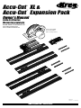
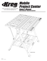
Accu-Cut
™
XL &
Accu-Cut
™
Expansion Pack
Owner’s Manual
Guide d’utilisation
Manual del propietario
NK9374
Version 1 - 10/2018
www.kregtool.com • 800.447.8638
Item# KMA3700/KMA2750
Article KMA3700/KMA2750
Artículo # KMA3700/KMA2750
Saw not included
Scie non incluse
No se incluye sierra

!
WARNING When using electric tools, always follow the safety precautions below to reduce the risk of re, electric shock,
and personal injury. Read all these instructions before attempting to operate this product. SAVE THESE INSTRUCTIONS.
General Safety Guidelines
1) Work area safety
a) Keep work area clean and well lit. Cluttered or dark areas
invite accidents.
b) Don’t use power tools in a dangerous environment. Don’t
use power tools in damp or wet locations, or expose them
to rain.
c) Do not operate power tools in explosive atmospheres,
such as in the presence of flammable liquids, gases or dust.
Power tools create sparks that can ignite the fumes or dust.
d) Keep children and bystanders away while operating a
power tool. Distractions can cause you to lose control.
e) Make your workshop child proof. Use padlocks, master
switches, or remove starter keys.
2) Electrical safety
a) Ground electric tools. If the tool is equipped with a three-
prong plug, it must be plugged into a grounded three-hole
electri cal outlet. If the proper outlet is not available, have one
installed by a qualified electrician. Never remove the third
prong or modify the provided plug in any way.
b) Do not expose power tools to rain or wet conditions. Water
entering a power tool increases the risk of electric shock.
c) Do not abuse the cord. Never use the cord for carrying,
pulling or unplugging the power tool. Keep cord away
from heat, oil, sharp edges or moving parts. Damaged or
entangled cords increase the risk of electric shock.
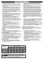
d) Use a proper extension cord and make sure it is in good
condition. When using an extension cord, be sure to use one
heavy enough to carry the current your power tool draws. An
undersized cord causes a drop in line voltage resulting in
loss of power and overheating. Table 1 shows the correct
cord gauge to use depending on cord length and tool
nameplate ampere rating. If in doubt, use the next heavier
gage. The smaller the gauge number, the heavier the cord.
e) When operating electric tools, avoid body contact with
grounded or earthed surfaces such as pipes, radiators,
kitchen ranges, and refrigerators. Contact with a grounded
surface increases the risk of electric shock.
3) Personal safety
a) Stay alert, watch what you are doing and use common
sense when operating a power tool. Do not use a power tool
while you are tired or under the influence of drugs, alcohol
or medication. A moment of inattention while operating
power tools can result in serious personal injury.
b) Always wear safety glasses. Everyday eyeglasses are
not safety glasses. Safety glasses have specially constructed
lenses, frames, and side shields.
c) Use safety equipment. Use a face or dust mask when the
cutting operation is dusty. Safety equipment such as a dust
mask, non-skid safety shoes, hard hat, or hearing protection
used for appropriate conditions reduces personal injuries.
d) Avoid accidental starting. Make sure the switch is in the
off-position before plugging in. Carrying power tools with
your finger on the switch or plugging in power tools that
have the switch on invites accidents.
e) Remove any adjusting key or wrench before turning the
power tool on. A wrench or a key left attached to a rotating
part of the power tool can result in personal injury.
f) Do not overreach. Keep proper footing and balance at
all times. This enables better control of the power tool in
unexpected situations.
g) Secure workpieces. Use clamps or a vise to hold work
when practical. This is safer than using your hand and it
frees both hands to operate the tool.
h) Never stand on the machine. Serious injury can occur if
the tool tips or if the cutting tool is unintentionally contacted.
i) Dress properly. Do not wear loose clothing or jewelry. Keep
your hair, clothing and gloves away from moving parts.
Loose clothes, jewelry or long hair can be caught in moving
parts. Roll up long sleeves to the elbow. Wear protective hair
covering to contain long hair.
j) If devices are provided for the connection of dust extraction
and collection equipment, ensure these are connected and
properly used. Use of these devices reduces dust-related
hazards.
4) Power tool use and care
a) Keep guards in place and in working order.
b) Do not force the power tool. Use the correct power tool for
your application. The correct power tool will do the job better
and safer at the rate for which it was designed.
c) Use the right tool. Don’t force a tool or attachment to do a
job for which it was not designed.
d) Do not use the power tool if the switch does not turn it
on and off. Any power tool that cannot be controlled with the
switch is dangerous and must be repaired.
e) Disconnect the plug from the power source and/
or the battery pack from the power tool before making any
adjustments, changing accessories, or storing power tools.
Such preventive safety measures reduce the risk of starting
the power tool accidentally.
f) Never leave a tool running unattended. Turn power off. Do
not leave the tool until it comes to a complete stop.
g) Store idle power tools out of the reach of children and do
not allow persons unfamiliar with the power tool and
these instructions to operate the power tool. Power tools are
dangerous in the hands of untrained users.
h) Maintain power tools. Check for misalignment or binding
of moving parts, broken parts, and any other condition that
can affect power tool operation. If damaged, have the power
tool repaired before use. Many accidents are caused by
poorly maintained power tools.
i) Keep cutting tools sharp and clean. Properly maintained
cutting tools with sharp cutting edges are less likely to bind
and are easier to control.
j) Use the recommended speed for the cutting tool or
accessory and workpiece material.
k) Only use parts and accessories recommended by the
manufacturer. Consult the owner’s manual for recommended
accessories. Using improper accessories can cause personal
injury.
l) Use the power tool, accessories, and tool bits in
accordance with these instructions and in the manner
intended for the particular type of power tool, taking into
account the working conditions and the work to be
performed. Use of the power tool for operations different
from those intended can result in a hazardous situation.
5) Service
a) Have your power tool serviced by a qualified repair person
using only identical replacement parts. This ensures that the
safety of the power tool is maintained.
6) SAFETY INSTRUCTIONS SPECIFIC TO USING THE ACCU-
CUT
™
XL AND EXPANSION PACK
a) Before using the Accu-Cut
™
XL and Accu-Cut XL
™
Expansion Pack, read, understand, and follow the safety
warnings and operation instructions included with this
product and provided by your saw manufacturer. Keep all
guards and safety devices in place.
b) Wear proper eye, ear, and respiratory protection when
operating your saw.
c) Use a sharp blade designed for the type of material you
are cutting.

General Safety Guidelines
TABLE 1
Nameplate
Amperes
@120 V
Extension Cord Length
25' 50' 75' 100' 150' 200'
Recommended Wire Gauge
0 -5 16 16 16 14 12 12
5.1 - 8 16 16 14 12 10 NR
8.1 -12 14 14 12 10 NR NR
12.1 - 16 12 12 NR NR NR NR
NR – Not Recommended
WARNING:
!
This product can expose you to chemicals including Acrylonitrile
and other chemicals, which are known to the State of California to cause cancer and
reproductive harm. For more information go to www.P65Warnings.ca.gov.
d) Always disconnect your saw from power before making
adjustments to the saw or Accu-Cut
™
XL.
e) Wipe the guide strips with a damp cloth and remove dust
and debris from the workpiece before positioning the track
on the workpiece.
f) Only use the number of track sections required to make a
cut, adding or removing track sections as necessary.
g) The Accu-Cut
™
XL is designed for use without clamps
only with two or more track sections joined together. Do
not attempt a cut using only one track section without first
clamping the track section to the work piece.
h) Ensure that the saw blade will not contact the aluminum
track during the cut.
i) Do not attempt a cut when any part of the Accu-Cut
™
XL
sled interferes with the operation of the saw blade guard.
j) Fully support both the workpiece and the cutoff piece to
prevent binding and kickback.
k) Adjust the depth of cut so the saw blade protrudes
1
⁄8”
[3mm] through the workpiece during the cut.
l) Keep your hands away from the saw blade during
operation. Do not reach under the workpiece while cutting.
m) Secure your workpiece to ensure it doesn’t move during
the cut.
n) Do not use excessive force when cutting. Maintain a
steady and controlled pace.
o) Allow the saw blade to come to a complete stop before
removing the saw/sled assembly from the track.
p) Do not leave unattended saw resting on the track or
starting block.
q) Maintain your tools and accessories. Check for
misalignment or binding of moving parts, loose fasteners,
broken parts, and any other condition that may affect safe
operation. If an unsafe condition is discovered, correct it
before use.
7) Kickback
Kickback is a sudden reaction to a pinched, bound, or
misaligned saw blade, causing an uncontrolled saw to lift up
and out of the workpiece toward the operator.
8) Causes of kickback
a) When the blade is pinched or bound tightly by the kerf
closing in, the blade stalls and the motor reaction drives the
unit rapidly back toward the operator.
b) If the blade becomes twisted or misaligned in the cut, the
teeth at the back edge of the blade can dig into the top
surface of the wood causing the blade to climb out of the
kerf and propel the saw back toward the operator.
Preventing kickback
Kickback is the result of tool misuse and/or incorrect
operating procedures or conditions and can be avoided by
taking proper precautions.
a) Maintain a firm grip with both hands on the saw and
position your body and arms to resist kickback forces.
Kickback forces can be controlled by the operator if proper
precautions are taken.
b) When blade starts to bind, or when interrupting a cut for
any reason, release the trigger and hold the saw motionless
in the material until the blade comes to a complete stop.
Never attempt to remove the saw from the work or pull the
saw backward while the blade is in motion. Investigate and
take corrective actions to eliminate the cause of blade binding.
c) When restarting a saw in the workpiece, center the saw
blade in the kerf and check that saw teeth are not engaged
in the material. If the saw blade is binding, the blade may
climb out of the workpiece and kickback as the saw is restarted.
d) Support large panels to minimize the risk of blade
pinching and kickback. Large panels tend to sag under their
own weight. Supports must be placed under the panel on
both sides of the cut: near the cutline and near the edge of
the panel.
e) Do not use a dull or damaged blade. A dull or improperly
sharpened blade produces a narrow kerf, causing excessive
friction, blade binding, and kickback.
f) Blade depth and bevel adjusting locks must be tight and
secure before making a cut. If blade adjustment shifts while
cutting, it may cause binding and kickback.
g) Use extra caution when making a plunge cut into existing
walls, floors, or other blind areas. The protruding blade may
contact unseen objects that can cause kickback.
Guidelines for extension cord use
Extension cords are only to be used for temporary purposes.
They do not replace the need for installation of outlets and
proper wiring where necessary.
In the shop and on construction sites:
1. Extension cords with an equipment grounding conductor
must be used at all times.
2. Extension cords must be protected from damage, and not
run through doorways or windows where the doors or
windows can close, causing damage to the cord.
3. Extension cords must be a minimum of 16 AWG and be
rated for the equipment in use.
4. Extension cords must be periodically inspected to ensure
that the insulation and conductivity of the wires are not
compromised.
5. Extension cords should not be run through water or
allowed to have connections that may be exposed to
accumulated water.

ENGLISH
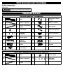
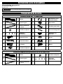
Accu-Cut
TM
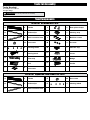
XL (KMA3700) Parts
A 4
Tracks
J 2
Base-plate clamps
B 8
Guide strips
K 1
Indexing stop
C 6
Steel connector bars
L 3
Machine screws
D 24
Set screws
M 3
Hex nuts
E 4
Indexing labels
N 1
Indicator clip
F 1
Starting block
O* 1
Cursor
G 1
Filler strip
P* 1
Wedge
H 1
Sled
Q* 1
Handle
I 2
Set screws
ATTENTION
!
Do not use power tools for assembly.
*Part functional only on Kreg Rip-Cut
™
.
Tools Needed:
#2 Phillips Screwdriver
Straight Edge
Saw Components
Accu-Cut
TM
Expansion Pack (KMA2750) Parts
A 2
Tracks
D 24
Set screws
B 8
Guide strips
E 4
Indexing labels
C 6
Steel connector bars
Tools for Assembly

ATTENTION
!
Do not overtighten the set screws. Overtightening
can cam-out the screw heads or damage the aluminum track.
ENGLISH
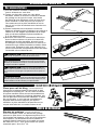
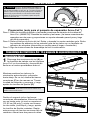
Assemble the Track
ATTENTION
!
The Accu-Cut
™
XL is designed for use with
portable circular saws that have a metal upper blade guard. When
paired with the Accu-Cut
™
XL, a saw with a plastic upper blade guard
may allow deection between the blade and the base plate resulting
in poor cut quality. Do not use a saw with a plastic upper blade guard
with the Accu-Cut
™
XL.
Before you begin
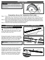
Preparation (Accu-Cut
™
Expansion Pack only)
Step 1: Remove the set screws and aluminum connector bars from your Accu-Cut
™
(KMA2700) tracks. Discard the screws and bars. (Replacement connector bars are
steel and provide proper support for the weight and length of the expansion track.)
Step 2: Remove the starting block from the track. Remove and discard all four guide strips.
Remove guide-strip adhesive residue from the tracks with a label-adhesive remover
(available at home centers and hardware stores).
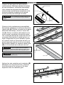
Step 3: Follow the Track Assembly instructions below.
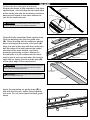
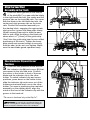
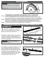
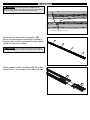
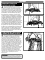
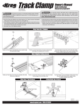
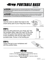
Keeping the tracks in the above orientation,
turn them upside down. Slide connector bars
(C) halfway into the T-slots in one track and
thread in and tighten the set screws (D).
Slide the second track onto the protruding
connector bars. Align the tracks with a
straight edge (48" level shown), tightly hold
together the two tracks, and thread in and
tighten the remaining set screws. Repeat
this process with the remaining two track
sections. You now have two track pairs.
Track Assembly (Accu-Cut
™
XL and Accu-Cut
™
Expansion Pack)
Logos
Arrows
Straight edge
A
C
A
C
D
D
Upper blade guard
1
Arrange two track sections (A) on your
work surface with the Accu-Cut
™
logos
at the ends and the arrow heads at center
pointing toward each other.

ATTENTION
!
Fully assembled track should contain six steel
connector bars with all 24 set screws installed and tightened.
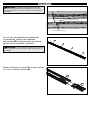
ATTENTION
!
Wipe the track surfaces that receive the guide strips
with a clean cloth before applying the strips as this will ensure proper
adhesion between the guide strip and track.
ATTENTION
!
Adhesive on the guide strip is off center and does
not cover the entire face of the strip.
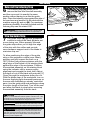
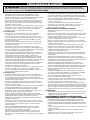
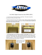
Assembly
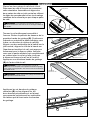
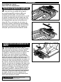
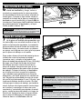
Position the two track pairs end to end.
Keeping the tracks in this orientation, turn them
upside down. Join and align the two track pairs
at the center joint with the remaining connector
bars and set screws in the same manner as
you did for each track pair.
Orient the fully assembled track upside down.
Peel the backing from the rst guide strip
(B). Orient the strip with the adhesive portion
down and toward the center of the track (A).
Align one end of the strip with the center joint,
butt the edge of the strip against the raised
shoulder of the track section, and rmly
press the guide strip in place. Make sure
the adhesive is in full contact with the track
section and is not exposed when the track is
right side up. Apply a second guide strip (B)
at the other edge of the track section.
Apply the remaining six guide strips (B) in
line with the rst two, tightly tting together
the ends. Do not leave gaps between guide
strips.
Center joint
Paired tracks
Paired tracks
Center joint
First guide strip
Raised shoulder
Second guide strip
This edge against track
section shoulder
Adhesive
Center joint
B
A
A
B
B
A
A
B
B
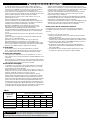
ENGLISH

ATTENTION
!
The tracks can be taken apart for storage.
Reassemble them in number order, as indicated by the labels.
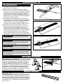
ATTENTION
!
The guide strips are slightly shorter than an
individual track section, overlap the outer track-section joints, and fall
short of the ends of the complete track assembly.
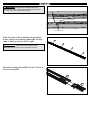
Assembly
With the track fully assembled and upside
down, apply the indexing labels (E) so they
read in sequence from left to right.
Slide the starting block (F) into the T-slots in
the end track (A).
Guide-strip overlap
Outer track-section joint
1
2
3
4
F
A
ENGLISH

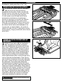
WARNING:
!
Disconnect the saw from power before mounting it on
the sled.
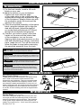
Assembly
Sled Assembly (Accu-Cut™ XL only)
H
K
I
J
H
G
I
J
G
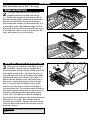
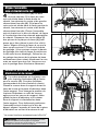
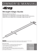
Orient the Filler Strip
Mount your Circular Saw on the Sled
2
The ller strip (G) on the sled (H) is
shipped with the angled ribs facing
up. These ribs support a saw base with an
angled leading edge, keeping the saw base
at on the sled when the set screws (I) in
the base-plate clamps (J) are tightened. For
a saw base with a at leading edge, lift the
ller strip from the sled recess with the tip of
a screwdriver, turn it over to expose the at
face, and press it into the recess.
3
Remove the indexing stop (K) from the
sled (H). Loosen the set screws (I) in
the base-plate clamps (J) and slide your saw
base plate under them. Position the saw on
the sled with the front of the saw base plate
against the step at the front of the sled. For
saws with the blade on the left-hand end of
the motor, center the blade in the left sled
slot. For saws with the blade on the right-
hand end of the motor, center the blade in
the right sled slot. To accommodate dierent
saw base-plate congurations, there are two
holes for attaching each base-plate clamp
to the sled. For the most secure clamping,
choose the holes that provide widest spacing
allowed by your saw. The clamps can be
oriented at an angle. Tighten the set screws
onto the saw base plate just enough to hold
the saw in place.
ENGLISH

ATTENTION
!
The sled assembly is equipped with features only
functional on the Kreg Rip-Cut
™
. Additional steps, found in the Rip-Cut
™
manual, are required to calibrate this sled for use on the Rip-Cut
™
.
Assembly
A
A
H
H
O*
N
Notch
Groove
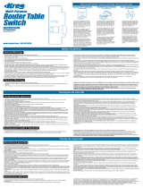
Align the Saw/Sled
Assembly on the Track
Check Indicator Clip and Cursor*
Positions
4
There are three grooves in the bottom
of the sled (H). For a saw with the blade
in the right-hand sled slot, the center and left
grooves ride on the track (A) rails. For a saw
with the blade in the left-hand sled slot, the
center and right grooves ride on the track
rails. Position the saw/sled assembly on
the starting block, engaging the appropriate
sled grooves. Loosen the base-plate clamp
(J) set screws (I) enough to slide the saw
side to side. Align the saw so the blade will
shave about
1
⁄32” [.8mm] o the guide strip.
(You’ll trim the guide strip later for zero-oset
positioning of the track.) Tighten the base-
plate clamp set screws enough to securely
hold the saw, but do not over tighten. Make
sure the saw blade guard operates freely.
5
There are two positions on the sled for
the indicator clip (N) and cursor (O) that
correspond to the two sled slots. Position
the cursor in the holder in front of the saw
blade and the indicator clip in the other
holder. To switch indicator clip and cursor
positions, press down on the holder locks,
slide the indicator clip and cursor out of the
holders and reinstall each one in the other
holder. For ease in positioning the saw/sled
assembly on the starting block, align the
notch at the front of the indicator clip with the
groove in the track rail.
*The cursor is functional only on the Rip-Cut
™
.
ENGLISH

ATTENTION
!
When mounting a different saw on the sled repeat
Steps 1-5. When installing a different blade in the saw, repeat Step 3.
WARNING:
!
The wedge lock is functional only on the Kreg
Rip-Cut
™
. To avoid interference with the operation of the Accu-Cut
™
, raise
the wedge (P) by pushing the handle (Q) forward and down. Make sure
the handle is in this position whenever using the Accu-Cut
™
.
ATTENTION
!
Always wipe the guide strips with a damp cloth and
remove dust and debris from the workpiece before positioning the track.
ATTENTION
!
Should the zero-offset guide strip become worn or
damaged, remove the starting block from the track and install it on the
other end. Perform the trimming operation on the second guide strip.
When the guide strips are no longer usable, contact Kreg Customer
Service to purchase replacements.
Assembly
K
L
M
B
Reinstall the Indexing Stop
Trim the Guide Strip
6
The indexing stop (K) allows you to
remove the saw from the sled assembly
and then re-mount it in exactly the same
position without having to re-trim the guide
strip. Place the indexing stop against the side of
the saw base and secure it to the sled with the
machine screw (L) and nut (M). For maximum
positioning exibility, the sled is slotted and the
indexing stop can be rotated 180°.
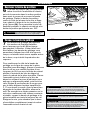
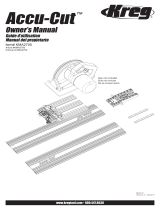
7
The guide strips (B) grip the workpiece
surface to ensure the track (A) does not
move during use. When properly trimmed,
the guide strips allow you to align the edge
of the strip with the cutline and provide
zero-clearance support next to the blade to
minimize chip-out.
To allow positioning the edge of the guide
strip on the workpiece cutline (zero oset),
position and fully support the track on a
100” [254cm]-long scrap workpiece with the
edge stop on the bottom of the starting block
against the edge of the workpiece. Position
the saw/sled assembly on the starting block
using the indicator clip to ensure proper
alignment and engage the track rails. Adjust
the depth of cut so the blade will protrude [⅛”]
[3mm] through the workpiece during the cut.
With the blade clear of the workpiece, turn on
the saw. Applying light downward pressure on
the saw and maintaining a steady, controlled
pace, trim the guide strip and workpiece along
the entire length of the track. Turn o the saw
and allow the blade to stop before removing
the saw/sled assembly from the track.
H
Cut Line
A
ENGLISH

WARNING:
!
Only use the number of track sections required to
make a cut, adding or removing track sections as necessary.
WARNING:
!
The Accu-Cut
™
is designed for use without clamps
only with two or more track sections joined together. Do not attempt a cut
using only one track section without rst clamping the track section to the
work piece.
WARNING:
!
Completely support the workpiece and cutoff with
2x4s or [2"] [50mm]-thick rigid foam insulation laid at on the oor.
WARNING:
!
When using one or two track sections and more than
12" of the end of the track opposite the starter block extends beyond
the workpiece, support the protruding end of the track with an auxiliary
surface that it is ush with the workpiece.
1) For the best results, install a 40-tooth
blade on your saw.
2) Mark the cutline on your workpiece.
Position the track with the edge
of the guide strip on the cutline and the
starting block edge stop against the edge
of the workpiece. Always make cuts with
the workpiece under the track and the
waste to the outside.
3) Place the saw/sled assembly on the starter
block, using the indicator clip to align the
sled with the track. Adjust the depth of
cut so the blade will protrude [⅛"] [3mm]
through the workpiece during the cut.
4) Connect your saw to power. With both
hands on the saw and the blade clear
of the workpiece, turn on the saw.
Applying light downward pressure on the
saw and maintaining a steady, controlled
pace, make the cut. Turn o the saw and
allow the blade to stop before removing
the saw/sled assembly from the track.
USING THE ACCU-CUT
TM
XL
Recommendations
OPTIONAL ACCESSORIES
Kreg Track Clamp (Sold separately)
These clamps slide into notches in the starter block
and T-slots in the track to allow the track to be
clamped to the workpiece. They are recommended
when cutting material with a slippery surface, such
as melamine-coated particleboard, or when any of
these conditions exist: the entire length of the track is
not fully supported by the workpiece, the workpiece
is not at, or when making cuts with a single section
of track.
REPLACEMENT PARTS
Guide Strips (Sold separately)
Over time, the guide strips can become worn and
no longer provide accurate alignment of the track
and zero-clearance chip prevention. This package
of two guide strips restores the accuracy and cut
quality of your Accu-Cut
™
. You’ll need four packs for
the Accu-Cut
™
XL.
ENGLISH
Page is loading ...
Page is loading ...
Page is loading ...
Page is loading ...
Page is loading ...
Page is loading ...
Page is loading ...
Page is loading ...
Page is loading ...
Page is loading ...
Page is loading ...
Page is loading ...
Page is loading ...
Page is loading ...
Page is loading ...
Page is loading ...
Page is loading ...
Page is loading ...
Page is loading ...
Page is loading ...

Have Questions? Need Help?
For assistance with any Kreg product, contact us through our Web site or call Customer Service.
www.kregtool.com • 800.447.8638
Tell Us About Your Experience. Your Opinion Counts.
We’re always working to improve Kreg
®
products and your satisfaction with them so that you have great
project-building experiences. You can help by sharing your feedback at www.kregtool.com/feedback. It only
takes a couple of minutes, and will help us to create products and support that serve your needs better.
Des questions? Besoin d’aide?
Si vous avez besoin d’aide concernant les produits Kreg, communiquez avec
nous sur notre site Web ou appelez notre service à la clientèle.
Parlez-nous de votre expérience. Votre opinion est importante pour nous.
Nous cherchons toujours à améliorer les produits Kreg® et à nous assurer que vous soyez satisfait
lorsque vous les utilisez pour eectuer vos projets de construction an de rendre votre expérience
agréable. Vous pouvez nous aider en nous faisant part de vos commentaires au www.kregtool.com/
feedback. Cela ne prend que quelques minutes, et vos commentaires nous aideront à créer des
produits et à fournir des services qui répondront mieux à vos besoins.
¿Tiene alguna pregunta? ¿Necesita ayuda?
Si requiere asistencia con cualquier producto Kreg, póngase en contacto con
nosotros a través del sitio web o llame al Servicio al Cliente.
Cuéntenos sobre su experiencia. Su opinión cuenta.
Siempre trabajamos para mejorar los productos Kreg
®
y su satisfacción con ellos para que
tenga excelentes experiencias de construcción de proyectos. Puede ayudar compartiendo
sus comentarios en www.kregtool.com/feedback. Solo toma un par de minutos y nos estará
ayudando a crear productos y brindar un soporte que sirva mejor a sus necesidades.
-
 1
1
-
 2
2
-
 3
3
-
 4
4
-
 5
5
-
 6
6
-
 7
7
-
 8
8
-
 9
9
-
 10
10
-
 11
11
-
 12
12
-
 13
13
-
 14
14
-
 15
15
-
 16
16
-
 17
17
-
 18
18
-
 19
19
-
 20
20
-
 21
21
-
 22
22
-
 23
23
-
 24
24
-
 25
25
-
 26
26
-
 27
27
-
 28
28
-
 29
29
-
 30
30
-
 31
31
-
 32
32


Kreg Accu-Cut Expansion Pack User manual
- Type
- User manual
- This manual is also suitable for
Ask a question and I''ll find the answer in the document
Finding information in a document is now easier with AI
in other languages
Related papers
-
 Kreg Accu-Cut User manual
-
Kreg Rip-Cut User manual
-
 Kreg Mobile Project Center User manual
-
 Kreg Track Clamp User manual
-
 Kreg Adaptive Cutting System Project Table Replacement Top User manual
-
 Kreg Straight Edge Guide Extension User manual
-
 Kreg Crosscut Station User manual
-
 Kreg Multi-Purpose Router Table Switch User manual
-
 Kreg Panel-Boring Pocket Hole-Machine User manual
-
 Kreg Portable Base User manual


Other documents
-
Gill POWERMAX SLED Operating instructions
-
 Otter Outdoors Universal Tow Hitch Adapter Assembly Instructions
-
Craftsman TS3650 User manual
-
Grizzly H8145 User manual
-
Grizzly G0771 Owner's manual
-
-
 Grizzly Industrial G0771Z User manual
-
-
-
Woodstock W1824 User manual

