Page is loading ...

WARRANTY
Hobbico
®
, Inc. guarantees this kit to be free from defects in both material and workmanship at the date of
purchase. This warranty does not cover any component parts damaged by use or modification. In no case shall
Hobbico’s liability exceed the original cost of the purchased model. Further, Hobbico reserves the right to change
or modify this warranty without notice. In that Hobbico has no control over the final assembly, no liability shall
be assumed nor accepted for any damage resulting from the use by the user of the final user-assembled product.
By the act of using the user-assembled product, the user accepts all resulting liability. If the buyers are not
prepared to accept the liability associated with the use of this product, they are advised to return this kit
immediately in new and unused condition to the place of purchase.
To make a warranty claim send the defective part or item to Hobby Services at the address below:
Include a letter stating your name, return shipping address, as much contact
information as possible (daytime telephone number, fax number, e-mail address),
a detailed description of the problem and a photocopy of the purchase receipt.
Upon receipt of the package the problem will be evaluated as quickly as possible.
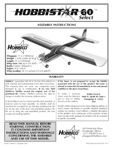
Wingspan: 68 in [1725mm]
Wing Area: 462 sq in [29.8 dm
2
]
Weight: 42–46 oz [1190–1305 g]
Wing Loading: 13.1–14.3 oz/sq ft [40–44 g/dm
2
]
Length: 45 in [1130mm]
Radio: 3-channel with 2 standard servos
Entire Contents © Copyright 2006
HCAZ2210 for HCAA2210 V1.0
™
Hobby Services
3002 N. Apollo Dr. Suite 1
Champaign IL 61822
USA
READ THROUGH THIS MANUAL BEFORE STARTING
CONSTRUCTION. IT CONTAINS IMPORTANT
INSTRUCTIONS AND WARNINGS CONCERNING
THE ASSEMBLY AND USE OF THIS MODEL.
Champaign, Illinois
(217) 398-8970 ext. 5

INTRODUCTION......................................................2
AMA..........................................................................2
SAFETY PRECAUTIONS.............................................3
ADDITIONAL ITEMS REQUIRED..............................3
Radio Equipment...................................................3
Adhesives and Building Supplies...........................4
Optional Supplies and Tools..................................4
IMPORTANT BUILDING NOTES ..............................4
KIT INSPECTION ......................................................5
KIT CONTENTS.........................................................5
ORDERING REPLACEMENT PARTS...........................6
ASSEMBLE THE WING ..............................................7
Make the Joiners ...................................................7
Attach the Reinforcement Plate .............................7
Join the Wing ........................................................8
ASSEMBLE THE FUSELAGE........................................8
Install the Tail Section ...........................................8
Install the Servos ...................................................9
Connect the Control Linkages .............................10
INSTALL THE MOTOR AND RADIO SYSTEM .........12
Install the Motor..................................................12
Assemble the Propeller........................................12
Install the Electronics ..........................................12
Install the Canopy ...............................................13
GET THE MODEL READY TO FLY............................14
Check the Control Directions..............................14
Set the Control Throws ........................................14
Balance the Model (C.G.)....................................14
Balance the Model Laterally................................15
PREFLIGHT .............................................................15
Identify Your Model .............................................15
Charge the Batteries ............................................15
Range Check.......................................................15
MOTOR SAFETY PRECAUTIONS ............................16
AMA SAFETY CODE................................................16
CHECK LIST ............................................................16
FLYING....................................................................17
Mount the Wing..................................................17
Trim Flights .........................................................17
First Flights..........................................................18
Thermal Flying ....................................................19
Facts about Thermals ...........................................19
Thermal Flying ....................................................19
Pointers for Contest Soaring ................................20
The Upstar ARF is a very predictable and stable aircraft,
allowing pilots of different skill levels to enjoy it. It is
easy to build, flies great, and is a great selection as your
first R/C aircraft.
For the latest technical updates or manual corrections to
the Upstar ARF visit the Hobbico web site at
www.hobbico.com. Open the “Airplanes” link, then
select the Upstar ARF. If there is new technical
information or changes to this model a “tech notice”
box will appear in the upper left corner of the page.
We urge you to join the AMA (Academy of Model
Aeronautics) and a local R/C club. The AMA is the
governing body of model aviation and membership is
required to fly at AMA clubs. Though joining the AMA
provides many benefits, one of the primary reasons to
join is liability protection. Coverage is not limited to
flying at contests or on the club field. It even applies to
flying at public demonstrations and air shows. Failure to
comply with the Safety Code (excerpts printed in the
back of the manual) may endanger insurance coverage.
Additionally, training programs and instructors are
available at AMA club sites to help you get started the
right way. There are over 2,500 AMA chartered clubs
across the country. Contact the AMA at the address or
toll-free phone number below:
Academy of Model Aeronautics
5151 East Memorial Drive
Muncie, IN 47302-9252
Tele. (800) 435-9262
Fax (765) 741-0057
Or via the Internet at: http://www.modelaircraft.org
IMPORTANT!!!
Two of the most important things you can do to preserve
the radio controlled aircraft hobby are to avoid flying
near full-scale aircraft and avoid flying near or over
groups of people.
AMA
INTRODUCTIONTABLE OF CONTENTS
2

1. Your Upstar ARF should not be considered a toy, but
rather a sophisticated, working model that functions
very much like a full-size airplane. Because of its
performance capabilities, the Upstar ARF, if not
assembled and operated correctly, could possibly cause
injury to yourself or spectators and damage to property.
2. You must assemble the model according to the
instructions. Do not alter or modify the model, as
doing so may result in an unsafe or unflyable model.
In a few cases the instructions may differ slightly from
the photos. In those instances the written instructions
should be considered as correct.
3. You must take time to build straight, true and strong.
4. You must use an R/C radio system that is in
first-class condition.
5. You must correctly install all R/C and other
components so that the model operates correctly on
the ground and in the air.
6. You must check the operation of the model before every
flight to insure that all equipment is operating and that
the model has remained structurally sound. Be sure to
check clevises or other connectors often and replace
them if they show any signs of wear or fatigue.
7. If you are not an experienced pilot or have not flown this
type of model before, we recommend that you get the
assistance of an experienced pilot in your R/C club for
your first flights. If you’re not a member of a club, your
local hobby shop has information about clubs in your
area whose membership includes experienced pilots.
8. While this kit has been flight tested to exceed normal use,
if the plane will be used for extremely high stress flying,
such as racing, the modeler is responsible for taking steps
to reinforce the high stress points and/or substituting
hardware more suitable for the increased stress.
Remember: Take your time and follow the instructions to
end up with a well-built model that is straight and true.
A 3-Channel radio system with a standard receiver and two
standard servos are the minimum requirements for the
Upstar ARF. The radio components can be purchased as
separate items or can be purchased as a package system. If
you already have a Futaba or Futaba compatible transmitter
you plan to use with this model, part numbers for the servos
and receiver are provided below:
(2) Futaba S3003 Standard Servo (FUTM0031)
Futaba R127DF 7-channel FM receiver w/o crystal
(low band – FUTL0702, high band – FUTL0703)
Futaba FM dual conversion receiver crystal for R127DF
(low band – FUTL57**, high band – FUTL58**)
If you plan to purchase a complete radio system, the
Futaba 4YF system is packaged with the Futaba R127DF
and four S3004 servos. The S3004 servo differs from the
S3003 servo mentioned above in that it is equipped
with ball bearings. Since only two servos are needed for
the glider, the other two that come in the package can
be saved for a future project. The order number is
provided below:
Futaba 4YF 4-Channel FM/4 S3004 Servos (FUTJ40**)
The asterisks in the part numbers refer to the channel
number of the radio system. When placing an order,
simply replace the asterisks with the channel number of
your choice.
RADIO EQUIPMENT
ADDITIONAL ITEMS REQUIRED
We, as the kit manufacturer, provide you with a top
quality, thoroughly tested kit and instructions, but
ultimately the quality and flyability of your finished
model depends on how you build it; therefore, we
cannot in any way guarantee the performance of your
completed model, and no representations are
expressed or implied as to the performance or safety
of your completed model.
PROTECT YOUR MODEL, YOURSELF
AND OTHERS. FOLLOW THESE
IMPORTANT SAFETY PRECAUTIONS
3

The included battery is a 9.6V 1800mAh NiMH pack. A
NiMH compatible charger is required. An economical choice
is the Great Planes ElectriFly 400 DC charger. (GPMM3001)
For a more advanced computerized charger, we
recommend the Great Planes Triton charger
(GPMM3150). Charge leads are not included with this
model charger, so order numbers for the correct
connector type, wire leads, and banana plugs are listed
below (soldering is required):
DuraTrax Battery Connector & Wire (DTXC2280)
Hobbico Banana Plugs (6) (HCAP0310)
This is the list of hardware and accessories required to
finish the Upstar ARF. Order numbers are provided
in parentheses.
❏ Pro 30-minute epoxy (GPMR6047)
❏ 1/2 oz. [15g] Thin Pro CA (GPMR6001)
❏ 1/2 oz. [15g] Medium Pro CA+ (GPMR6007)
❏ Drill bits: 1/16" [1.6mm], 5/64" [2mm], 1/8" [3.2mm]
❏ Hobby knife with #11 blade
❏ Philips Screwdriver
❏ Ruler
❏ Threadlocker (GPMR6060)
Here is a list of optional tools mentioned in the manual
that will help you build the Upstar ARF.
❏ Stick-on segmented lead weights (GPMQ4485)
❏ 2 oz. [57g] spray CA activator (GPMR6035)
❏ CA applicator tips (HCAR3780)
❏ CA debonder (GPMR6039)
❏ Curved-tip canopy scissors (HCAR0667)
❏ Robart Super Stand II (ROBP1402)
❏ Denatured alcohol (for epoxy clean up)
❏ Small clamps
❏ Felt tip pen
• There are two types of screws used in this kit:
Sheet metal screws are designated by a number and
a length.
For example #6 x 3/4" [19mm]
This is a number six screw that is 3/4" [19mm] long.
Machine screws are designated by a number, threads
per inch, and a length.
For example 4-40 x 3/4" [19mm]
This is a number four screw that is 3/4" [19mm] long
with forty threads per inch.
• When you see the term test fit in the instructions, it
means that you should first position the part on the
assembly without using any glue, then slightly modify
or custom fit the part as necessary for the best fit.
• Whenever the term glue is written you should rely
upon your experience to decide what type of glue to
use. When a specific type of adhesive works best for
that step, the instructions will make a recommendation.
• Whenever just epoxy is specified you may use either
30-minute (or 45-minute) epoxy or 6-minute epoxy.
When 30-minute epoxy is specified it is highly
recommended that you use only 30-minute (or 45-
minute) epoxy, because you will need the working time
and/or the additional strength.
• Photos and sketches are placed before the step they
refer to. Frequently you can study photos in following
steps to get another view of the same parts.
• The stabilizer and wing incidences and engine thrust
angles have been factory-built into this model.
However, some technically-minded modelers may wish
to check these measurements anyway. To view this
information visit the web site at www.hobbico.com and
click on “Technical Data.” Due to manufacturing
tolerances which will have little or no effect on the way
your model will fly, please expect slight deviations
between your model and the published values.
IMPORTANT BUILDING NOTES
OPTIONAL SUPPLIES & TOOLS
ADHESIVES & BUILDING SUPPLIES
CHARGER
4

5
Before starting to build, take an inventory of this kit to make sure it is complete, and inspect the parts to make
sure they are of acceptable quality. If any parts are missing or are not of acceptable quality, or if you need
assistance with assembly, contact Product Support. When reporting defective or missing parts, use the part names
exactly as they are written in the Kit Contents list.
Hobbico Product Support:
3002 N Apollo Drive, Suite 1
Champaign, IL 61822
Telephone: (217) 398-8970, ext. 5
Fax: (217) 398-7721
E-mail: [email protected]
KIT INSPECTION
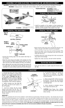
1 Fuselage
2 Pushrods
3 Center wing section
4 Left wing section
5 ESC
6 Motor
7 Spinner
8 Folding prop
9 Vertical fin
10 Horizontal stabilizer
11 Right wing section
12 Canopy
13 Battery pack 9.6V
14 Radio tray
15 Wood dowels
16 Rubber band
reinforcement plate
17 Plywood wing joiners
Kit Contents (Photographed)
(4) 2mm Nuts
(2) 2mm Flat washers
(4) 2 x 12mm Machine screws
(2) Control horns with backplates
(2) Hook and loop material
(8) 2.6 x 6mm Screws
(2) Nylon clevises
(2) Silicone clevis retainers
(2) Nylon fasLinks
(2) 3 x 8mm Machine screws
(2) 3mm Flat washers
(2) 2 x 10mm Prop pins
(4) #2 x ½" Screws
(1) 3 x 3mm Set screw
Kit Contents (Not Photographed)
KIT CONTENTS
1
2
3
4
5
6
7
8
9
10
11
12
13
14
15
16
17

Replacement parts for the Hobbico Upstar are available using the order numbers in the Replacement Parts List that
follows. The fastest, most economical service can be provided by your hobby dealer or mail-order company.
To locate a hobby dealer, visit the Hobbico web site at www.hobbico.com. Choose “Where to Buy” at the bottom
of the menu on the left side of the page. Follow the instructions provided on the page to locate a U.S., Canadian
or International dealer. If a hobby shop is not available, replacement parts may also be ordered from Tower
Hobbies
®
at www.towerhobbies.com, or by calling toll free (800) 637-6050.
Parts may also be ordered directly from Hobby Services by calling (217) 398-0007, or via facsimile at (217) 398-
7721, but full retail prices and shipping and handling charges will apply. Illinois and Nevada residents will also be
charged sales tax. If ordering via fax, include a Visa
®
or MasterCard
®
number and expiration date for payment.
Mail parts orders and payments by personal check to:
Hobby Services
3002 N Apollo Drive, Suite 1
Champaign IL 61822
Be certain to specify the order number exactly as listed in the Replacement Parts List. Payment by credit card or
personal check only; no C.O.D.
If additional assistance is required for any reason contact Product Support by e-mail at [email protected], or
by telephone at (217) 398-8970.
6
REPLACEMENT PARTS LIST
ORDER NUMBER DESCRIPTION HOW TO PURCHASE
HCAA3760...........................WING SET UPSTAR EP GLIDER ......................Hobby Supplier
HCAA3761 .......................FUSELAGE SET UPSTAR EP GLIDER ...................Hobby Supplier
HCAA3762 ............................TAIL SET UPSTAR EP GLIDER........................Hobby Supplier
HCAA3763............................CANOPY UPSTAR EP GLIDER .......................Hobby Supplier
HCAA3764 ......................FOLDING PROP UPSTAR EP GLIDER..................Hobby Supplier
HCAA3765.............................MOTOR UPSTAR EP GLIDER ........................Hobby Supplier
HCAA3766 ................................ESC UPSTAR EP GLIDER............................Hobby Supplier
HCAA3767 .......................BATTERY PACK UPSTAR EP GLIDER...................Hobby Supplier
Missing pieces........................Contact Product Support
Instruction manual ....................Contact Product Support
Full-size plans.................................Not available
ORDERING REPLACEMENT PARTS

❏ 1. Locate the two thick and four thin plywood wing
joiner pieces. Make two wing joiners by laminating one
thick piece between two thin pieces with 30-minute
epoxy. Clamp the pieces together while the epoxy cures
and use denatured alcohol to wipe away any excess
squeeze out. Make sure the edges of the three joiner
pieces are flush.
❏ 2. While waiting for the wing joiner epoxy to cure,
find the exact center of the center wing section and
make a mark with a felt tip pen on the trailing edge.
❏ 3. Do the same on the rubber band reinforcement plate.
❏ 4. Place the reinforcement plate on the top of the
center wing section and line up the trailing edges and
the two marks that you made. Trace around the
reinforcement plate.
❏ 5. With a new blade in your hobby knife, carefully
cut the covering just inside your line being sure not to
cut into the wood beneath. Pull the covering away and
use alcohol to wipe away the line you drew. Leave the
two marks you made on the trailing edges until after you
have glued the part.
❏ 6. Realign the plate on the center wing section and
glue it in place.
ATTACH THE REINFORCEMENT PLATE
MAKE THE JOINERS
ASSEMBLE THE WING
7

❏ 1. Test fit the wing together using the wing joiners. Be
sure that the joiners fit into each joiner pocket properly. Trim
or sand the joiners lightly as necessary so that the joiners
can slide halfway into their mating pockets.
❏ 2. When satisfied with their fit, use 30-minute epoxy
to glue the three wing pieces together. Coat one half of
each wing joiner on all sides and insert them into the
wing center section. Cover the mating wing ribs with
epoxy and the other ends of the wing joiners. Slide the
wing pieces together snugly. Wipe away any excess
epoxy with alcohol and use masking tape to secure
them together while the epoxy cures. If necessary, use
small clamps to align the trailing edges. We suggest
gluing only one wing section at a time.
❏ 1. Use a hobby knife or drill to open the upper right
and lower left pushrod exit holes on the fuselage to
approximately 1/8" [3.2mm].
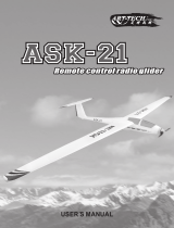
❏ 2. Slide the pre-installed vertical fin bolts through the
holes in the horizontal stabilizer.
❏ 3. Attach the tail to the fuselage by pushing the bolts
through the pre-drilled holes. Secure each bolt with a 2mm
flat washer and two 2mm nuts. Tighten the second nut on
each bolt firmly against the first, to lock it in place.
VERTICAL
FIN
VERTICAL FIN
BOLTS
HORIZONTAL
STABILIZER
2mm NUTS
(
2
)
2mm WASHER
INSTALL THE TAIL SECTION
ASSEMBLE THE FUSELAGE
JOIN THE WING
8

❏ 4. Position the rudder control horn on the right side
of the rudder so that it is 3/8" [9.5mm] from the bottom
of the vertical fin and at a slight angle downward. Mark
the mounting holes and drill them out with a 5/64"
[2mm] drill bit. Attach the control horn using (2) 2-56 x
1/2" [13mm] screws and a control horn backing plate.
❏ 5. Attach the elevator control horn on the left underside
of the elevator 3/8" [9.5mm] from the fuselage.
❏ 1. Cut the servo tray and servo tray supports from the
1/8" [3mm] plywood sheet.
❏ 2. Fit the servo tray supports to the servo tray and glue
them on using medium CA glue.
❏ 3. Place your rudder and elevator servos into the
cutout on the servo tray. Mark and drill 1/16" [1.6mm]
holes for the servo mounting screws. Reinforce the
holes with a couple drops of thin CA glue. Install the
servos with the output splines facing forward using the
hardware provided with the servos.
INSTALL THE SERVOS
Correct Incorrect
9

❏ 4. Overlap two sets of hook and loop material by
approximately 3" [76mm].
❏ 5. Wrap the hook and loop material around the
notches in the radio tray.
❏ 6. Maneuver the radio tray assembly into the
fuselage. Squeezing or skewing the fuselage slightly
while sliding the tray back will allow it to fit into place.
❏ 7. Position the tray so that the front tips of the tray are
3/8" [9.5mm] forward of the front mounting holes.
Using a 1/16" [1.6mm] bit, drill out the six mounting
holes and secure the radio tray with (6) #2 x 1/4" [6mm]
screws. There are two indented mounting screw holes
on each side of the fuselage and two toward the front of
the radio tray.
❏ 1. Thread two nylon clevises along with two silicone
clevis retainers onto the two 24" [610mm] pushrods. Be
sure that each clevis is threaded on approximately 14
complete rotations.
CONNECT THE CONTROL LINKAGES
10

❏ 2. Center the servos by temporarily turning on your radio
system. Cut off unused arms leaving only one arm on each
horn. Cut off the two outer-most holes from each remaining
servo arm. Enlarge the holes in the horns that are 7/16" [11
mm] from the center to accommodate the diameter of the
pushrod wires. Attach servo horns opposite each other to
the rudder and elevator servos.
❏ 3. Slide the pushrods into the fuselage through the
pushrod exit slots and temporarily connect the rudder
clevis to the middle hole in the rudder control horn and
the elevator clevis to the fourth outer hole in the
elevator control horn.
❏ 4. Adjust the rudder and elevator so they are in the
neutral position. Mark the location on each pushrod
where they cross the enlarged holes in the servo horns.
❏ 5. Remove the pushrods from the fuselage and make
a 90 degree bend at each mark. Cut off the excess wire
leaving only ¼" [6mm] remaining after the bend.
❏ 6. Reinstall the pushrods into the fuselage and
connect them to the servo horns using the included
Faslinks. Hook up the clevises to the control horns and
secure them with the silicone clevis retainers.
11

❏ 1. Using two 3 x 8mm machine screws and two #4
flat washers, secure the motor to the fuselage with the
plywood reinforcement plate by sliding the motor into
the opening in the front of the fuselage. Align the screw
holes in the motor with the hole in the firewall and
reinforcement plate. Use a drop of thread-locker on
each screw.
❏ 1. Attach the folding propeller blades to the hub by
pressing the two 2 x 10 mm pins through the holes.
❏ 2. The spinner is held to the hub with two #2 x 1/2"
[13 mm] screws. Use the 3 x 3mm set screw to attach the
propeller assembly to the motor shaft. Be sure that the set
screw is tightened against the flat cutout on the motor shaft.
❏ 1. Loosen the hook and loop straps you installed
earlier and slide the battery pack into position. Small
pieces of the included self-adhesive hook and loop
material attached to the underside of the pack will
prevent it from sliding back and forth during flight and
allow you to alter its position for balancing the model.
With the self-adhesive hook and loop material attached
to the front end of the battery pack, you will be able to
remove and replace it without taking off the wing.
❏ 2. Install the receiver with hook and loop material in
the open area in front of the battery pack. Run the
antenna down the inside and out the back of the
fuselage. In the example shown above, we drilled a
small hole at the aft end of the fuse and used some
flexible wire to fish the antenna through the hole. A
strain relief made from a leftover servo arm was then
installed to prevent the antenna from pulling back into
the fuselage.
INSTALL THE ELECTRONICS
ASSEMBLE THE PROPELLER
INSTALL THE MOTOR
INSTALL THE MOTOR & RADIO SYSTEM
12

❏ 1. Connect the included electronic speed controller
to the motor leads and to the receiver. Using a piece of
self-adhesive hook and loop material, secure the ESC to
the fuselage. You can also affix the ESC switch in a
convenient location. Hook the servos up to the
appropriate channels on the receiver.
❏ 2. Trim the canopy along the molded-in cut lines. Test
fit the canopy on the fuselage and sand as necessary
until it fits well.
❏ 3. When satisfied with the fit, position it onto the
fuselage and drill two 1/16" [1.6mm] holes at the front
and back and secure it to the fuselage using (2) #2 x 1/4"
[6mm] screws.
❏ 4. Slide the two wooden dowels into the dowel holes
in the fuselage. The longer dowel installs in front. Center
the wing onto the fuse and secure it with the included
rubber bands.
INSTALL THE CANOPY
13

1. Turn on the transmitter and receiver and center the
trims. If necessary, remove the servo arms from the
servos and reposition them so they are centered.
Reinstall the screws that hold on the servo arms.
2. With the transmitter and receiver still on, check all
the control surfaces to see if they are centered. If
necessary, adjust the clevises on the pushrods to center
the control surfaces.
3. Make certain that the control surfaces and the motor
respond in the correct direction as shown in the
diagram. If any of the controls respond in the wrong
direction, use the servo reversing in the transmitter to
reverse the servos connected to those controls. Be
certain the control surfaces have remained centered.
Adjust if necessary.
Use a ruler to accurately measure and set the control
throw of each control surface as indicated in the chart
that follows. If your radio does not have dual rates, we
recommend setting the throws at the low rate setting.
This can be accomplished by moving the clevises
further outward on the control horns.
NOTE: The throws are measured at the widest part of
the elevator and rudder.
At this stage the model should be in ready-to-fly
condition with all of the systems in place including the
battery pack and the radio system.
❏ 1. Use a felt-tip pen or 1/8" [3mm]-wide tape to
accurately mark the C.G. on the bottom of the wing on
both sides of the fuselage. The C.G. is located 2-1/2"
[64 mm] back from the leading edge of the wing.
This is where your model should balance for the first
flights. Later, you may wish to experiment by shifting
the C.G. up to 3/8" [10mm] forward or 3/8" [ 10mm]
back to change the flying characteristics. Moving the
C.G. forward may improve the smoothness and
stability, but the model may then require more speed
for takeoff and make it more difficult to slow for
landing. Moving the C.G. aft makes the model more
maneuverable, but could also cause it to become too
difficult to control. In any case, start at the
recommended balance point and do not at any time
balance the model outside the specified range.
More than any other factor, the C.G. (balance point) can
have the greatest effect on how a model flies, and may
determine whether or not your first flight will be
successful. If you value this model and wish to enjoy it for
many flights, DO NOT OVERLOOK THIS IMPORTANT
PROCEDURE. A model that is not properly balanced will
be unstable and possibly unflyable.
BALANCE THE MODEL (C.G.)
IMPORTANT: The Upstar ARF has been extensively
flown and tested to arrive at the throws at which it flies
best. Flying your model at these throws will provide you
with the greatest chance for successful first flights. If, after
you have become accustomed to the way the Upstar
ARF flies, you would like to change the throws to suit
your taste, that is fine. However, too much control throw
could make the model difficult to control, so remember,
“more is not always better.”
These are the recommended control surface throws:
High Rate Low Rate
ELEVATOR 3/8" [10mm] up 1/4" [6mm] up
3/8" [10mm] down 1/4" [6mm] down
RUDDER 7/8" [22mm] right 9/16" [14mm] right
7/8" [22mm] left 9/16" [14mm] left
SET THE CONTROL THROWS
3-CHANNEL
TRANSMITTER
TRANSMITTER
3-CHANNEL
TRANSMITTER
3-CHANNEL
CHECK THE CONTROL DIRECTIONS
GET THE MODEL READY TO FLY
14

❏ 2. With the wing attached to the fuselage, all parts of
the model installed (ready to fly), place the model on a
Great Planes CG Machine, or lift it at the balance point
you marked.
❏ 3. If the tail drops, the model is “tail heavy” and the
battery pack and/or receiver must be shifted forward or
weight must be added to the nose to balance. If the nose
drops, the model is “nose heavy” and the battery pack
and/or receiver must be shifted aft or weight must be
added to the tail to balance. If possible, relocate the
battery pack and receiver to minimize or eliminate any
additional ballast required. If additional weight is
required, it may be easily added by using Great Planes
(GPMQ4485) “stick-on” lead. Begin by placing
incrementally increasing amounts of weight on the
bottom of the fuse until the model balances. Once you
have determined the amount of weight required, it can
be permanently attached.
❏ 4. IMPORTANT: If you found it necessary to add any
weight, recheck the C.G. after the weight has been installed.
❏ 1. With the wing level, have an assistant help you lift
the model by the engine propeller shaft and the bottom
of the fuse under the TE of the fin. Do this several times.
❏ 2. If one wing always drops when you lift the model,
it means that side is heavy. Balance the airplane by
adding weight to the other wing tip. An airplane that
has been laterally balanced will track better in loops
and other maneuvers.
No matter if you fly at an AMA sanctioned R/C club site
or if you fly somewhere on your own, you should
always have your name, address, telephone number
and AMA number on or inside your model. It is
required at all AMA R/C club flying sites and AMA
sanctioned flying events.
Follow the battery charging instructions that came with
your radio control system to charge the batteries. You
should always charge your transmitter the night before
you go flying, and at other times as recommended by
the radio manufacturer.
The included 1800mAh NiMH battery pack should be
charged by a NiMH-compatible charger at no more
than 1.5A. Compatible chargers available are listed on
page 4 of this manual. At the 1.5A charge rate, the
battery pack should take a little more than one hour to
charge when fully depleted. Rates less than 1.5A will
take longer to completely charge the pack. The fully
charged battery pack voltage should not exceed 12V.
Always monitor the battery pack during a charge. The
pack may get warm during charging but should not get
hotter than 125°F. If the pack gets too hot, disconnect it
from the charger and allow it to cool.
Ground check the operational range of your radio before
the first flight of the day. With the transmitter antenna
collapsed and the receiver and transmitter on, you should
be able to walk at least 100 feet away from the model and
still have control. Have an assistant stand by your model
and, while you work the controls, tell you what the control
surfaces are doing. Repeat this test with the engine running
at various speeds with an assistant holding the model, using
RANGE CHECK
CAUTION: Unless the instructions that came with your
radio system state differently, the initial charge on new
transmitter and receiver batteries should be done for 15
hours using the slow-charger that came with the radio
system. This will “condition” the batteries so that the next
charge may be done using the fast-charger of your
choice. If the initial charge is done with a fast-charger the
batteries may not reach their full capacity and you may
be flying with batteries that are only partially charged.
CHARGE THE BATTERIES
IDENTIFY YOUR MODEL
PREFLIGHT
BALANCE THE MODEL LATERALLY
15

hand signals to show you what is happening. If the control
surfaces do not respond correctly, do not fly! Find and
correct the problem first. Look for loose servo connections
or broken wires, corroded wires on old servo connectors,
poor solder joints in your battery pack or a defective cell, or
a damaged receiver crystal from a previous crash.
Do not run the engine in an area of loose gravel or sand; the
propeller may throw such material in your face or eyes.
Keep your face and body as well as all spectators away
from the plane of rotation of the propeller as you start
and run the engine.
Keep these items away from the prop: loose clothing,
shirt sleeves, ties, scarfs, long hair or loose objects such
as pencils or screwdrivers that may fall out of shirt or
jacket pockets into the prop.
Read and abide by the following excerpts from the
Academy of Model Aeronautics Safety Code. For the
complete Safety Code refer to Model Aviation
magazine, the AMA web site or the Code that came
with your AMA license.
General
1) I will not fly my model aircraft in sanctioned events,
air shows, or model flying demonstrations until it has
been proven to be airworthy by having been previously,
successfully flight tested.
2) I will not fly my model aircraft higher than
approximately 400 feet within 3 miles of an airport
without notifying the airport operator. I will give right-
of-way and avoid flying in the proximity of full-scale
aircraft. Where necessary, an observer shall be utilized
to supervise flying to avoid having models fly in the
proximity of full-scale aircraft.
3) Where established, I will abide by the safety rules for
the flying site I use, and I will not willfully and
deliberately fly my models in a careless, reckless and/or
dangerous manner.
5) I will not fly my model unless it is identified with my name
and address or AMA number, on or in the model. Note: This
does not apply to models while being flown indoors.
7) I will not operate models with pyrotechnics (any
device that explodes, burns, or propels a projectile of
any kind).
Radio Control
1) I will have completed a successful radio equipment ground
check before the first flight of a new or repaired model.
2) I will not fly my model aircraft in the presence of
spectators until I become a qualified flier, unless
assisted by an experienced helper.
3) At all flying sites a straight or curved line(s) must be
established in front of which all flying takes place with the
other side for spectators. Only personnel involved with
flying the aircraft are allowed at or in the front of the flight
line. Intentional flying behind the flight line is prohibited.
4) I will operate my model using only radio control
frequencies currently allowed by the Federal
Communications Commission.
5) I will not knowingly operate my model within three
miles of any pre-existing flying site except in
accordance with the frequency sharing agreement
listed [in the complete AMA Safety Code].
9) Under no circumstances may a pilot or other person
touch a powered model in flight; nor should any part of
the model other than the landing gear, intentionally
touch the ground, except while landing.
❏ 1. Check the C.G. according to the measurements
provided in the manual.
❏ 2. Be certain the battery and receiver are securely
mounted in the fuse. Simply stuffing them into
place with foam rubber is not sufficient.
❏ 3. Extend your receiver antenna and make sure it has
a strain relief inside the fuselage to keep tension
off the solder joint inside the receiver.
❏ 4. Balance the model laterally as explained in
the instructions.
During the last few moments of preparation your mind
may be elsewhere anticipating the excitement of the first
flight. Because of this, you may be more likely to
overlook certain checks and procedures that should be
performed before the model is flown. To help avoid this,
a check list is provided to make sure these important
areas are not overlooked. Many are covered in the
instruction manual, so where appropriate, refer to the
manual for complete instructions. Be sure to check the
items off as they are completed.
CHECK LIST
AMA SAFETY CODE (excerpts)
Failure to follow these safety precautions may result
in severe injury to yourself and others.
MOTOR SAFETY PRECAUTIONS
16

❏ 5. Reinforce holes for wood screws with thin CA
where appropriate (servo mounting screws, etc.).
❏ 6. Confirm that all controls operate in the correct
direction and the throws are set up according to
the manual.
❏ 7. Make sure there are silicone retainers on all the
clevises and that all servo arms are secured to the
servos with the screws included with your radio.
❏ 8. Place your name, address, AMA number and
telephone number on or inside your model.
❏ 9. If you wish to photograph your model, do so
before your first flight.
❏ 10. Range check your radio when you get to the
flying field.
Mount the wing to the fuselage with 6 of the included
rubber bands or #64 Great Planes, Hobbico or similar
rubber bands. Install them from front to back,
crisscrossing the last two. Never use torn, cracked or
oily rubber bands. After removing the rubber bands
from your model, store them in a container with talcum
powder or clay-type kitty litter to absorb oil and keep
them fresh for the next flying session.
If the rubber bands you will be using are different from
those recommended, consult an experienced modeler
to make certain they are strong enough, and that you
have used enough of them. If uncertain, force the front
of the wing off of the wing saddle. There should be
considerable resistance! If the wing can be forced from
the fuselage without having to strain your hands, then
there are probably not enough rubber bands.
The Upstar ARF is a great-flying model that flies
smoothly and predictably. The Upstar ARF does not,
however, possess the self-recovery characteristics of a
primary R/C trainer and should be flown only by
experienced R/C pilots.
It is a good idea to do a couple of trim flights, without the
motor running, before each flying session to make sure the
plane is still in trim and the radio is working properly. The
model will survive a hard landing from 5 feet much better
than it will one from several hundred feet. The first few trim
flights should be done over a grass field. The longer the grass
the better (more cushion).
Turn on the transmitter first and then the receiver. Hold the
Upstar ARF under the wing with the nose pointed slightly
down and directly into the wind. Do not run the motor for
these test flights. It is very important that you launch the
model with the wings level and the nose pointing at a spot
on the ground about 50 feet in front of you. Have a friend
stand off to the side of you and tell you whether the nose is
pointing up or down. Show your friend the picture above so
TRIM FLIGHTS
CAUTION (THIS APPLIES TO ALL R/C AIRPLANES): If,
while flying, you notice an alarming or unusual sound
such as a low-pitched “buzz,” this may indicate control
surface flutter. Flutter occurs when a control surface
(such as an aileron or elevator) or a flying surface (such
as a wing or stab) rapidly vibrates up and down (thus
causing the noise). In extreme cases, if not detected
immediately, flutter can actually cause the control
surface to detach or the flying surface to fail, thus
causing loss of control followed by an impending crash.
The best thing to do when flutter is detected is to slow
the model immediately by reducing power, then land as
soon as safely possible. Identify which surface fluttered
(so the problem may be resolved) by checking all the
servo grommets for deterioration or signs of vibration.
Make certain all pushrod linkages are secure and free of
play. If it fluttered once, under similar circumstances it
will probably flutter again unless the problem is fixed.
Some things which can cause flutter are; Excessive
hinge gap; Not mounting control horns solidly; Poor fit
of clevis pin in horn; Side-play of wire pushrods caused
by large bends; Excessive free play in servo gears;
Insecure servo mounting; and one of the most prevalent
causes of flutter; Flying an over-powered model at
excessive speeds.
IMPORTANT!!!
Flying a model with too few rubber bands can be
dangerous. If the wing momentarily lifts from the
fuselage and acts as though a large amount of “up”
elevator has suddenly been applied because there
are not enough rubber bands or they are too weak,
internal structural damage may result. Even worse,
the wing could actually detach from the fuselage
resulting in a crash. If the model exhibits any
tendencies that indicate there are not enough rubber
bands, immediately reduce power, land and closely
inspect the model for damage. If no damage is found,
add more rubber bands.
MOUNT THE WING
FLYING
17

he will know what to look for. If the Upstar ARF is launched
with the nose up or launched too hard it will climb a few
feet, stall and fall nose first straight down. With the nose
pointed down slightly the sailplane will accelerate down
until it picks up enough flying speed then level off and glide
forward. The plane should be launched with a gentle push
forward. With a little practice you will be able to launch it
at just the right speed so it soars straight ahead in a long and
impressive glide path. Adjust the trims on your transmitter to
get the plane to fly straight ahead in a smooth glide path.
Once you get the hang of launching it you can try
turning the plane during the trim flights by gently
applying a “touch” of right or left rudder. You can also
try “flaring” the landings by slowly applying a touch of
up elevator (pull the stick back) as the plane nears the
ground. The Upstar ARF will continue to fly just a few
inches off the ground for a surprisingly long distance. It
is important you don’t “over-control” the model. Make
any control inputs slowly and smoothly rather than
moving the transmitter sticks abruptly.
Find a BIG, OPEN field for your first flights. The bigger the
better as you won’t have to worry about where you need to
land. Ground based objects (trees, poles, buildings, etc.)
seem to attract model airplanes like a magnet. Again, we
would like to recommend that you find an experienced
pilot to help you with these first flights. Note: You need
to remember that your radio control responds as if you
were sitting in the cockpit. When you push the
transmitter stick to the right, the rudder moves to the
plane’s right! This means that when the plane is flying
towards you it may seem like the rudder controls are
reversed (when you give “right” rudder the plane turns
to your left–which is the plane’s “right”). It is sometimes
easier to learn to fly the plane if you always face your
body in the direction the plane is flying and look over
your shoulder to watch the model.
Turn on your transmitter and then your receiver and hold
the model as you did for the hand launched test flights.
Hold it firmly and move the throttle stick up to test the
motor operation. When satisfied that everything is
responding as it should, launch the model straight into the
wind just as you did without the motor running. It is
important that you do not throw the airplane up or it may
stall an hit the ground. If you launch it level or slightly down
the airplane will accelerate and start climbing on its own.
Don’t worry about accomplishing very much on your first
flights. Use these flights to get the “feel” of the controls and
the Upstar ARF’s flying characteristics. For the first few
seconds of the flight allow the airplane to gently climb
straight ahead. Try to keep the plane upwind and just
perform some gentle “S-turns” (always turning into the
wind) until it is time to set up for landing. Have a helper
adjust the trims on your transmitter (a little at a time) until
it has reached a comfortable soaring altitude (200’ - 300’).
Turn the motor off and allow the Upstar ARF to soar
around, keeping the airplane upwind of yourself. When
you feel its getting too low, turn the motor back on and
climb back to altitude. It can be very hard for a beginner to
fly a plane straight towards him as he would have to do if
the plane were downwind. While the Upstar ARF is gliding
have a helper to adjust the trims on your transmitter (a little
at a time) until the plane will fly straight and level with the
transmitter sticks in their neutral position.
When you can hear the motor starting to die off and/or
the plane does not want to climb anymore it is time to
shut off the motor for the last time (especially if you
have BEC.) It is important to remember that you no
longer have enough power to climb out again, so you
only get one chance at landing. When it is time to land,
just continue performing the gentle “S-turns” upwind
and let the plane glide onto the ground. Don’t worry
about where the plane lands–just miss any trees, etc. If
you need to “stretch” a landing you can switch the
motor back on but do not expect it to be able to carry
you very far. When NiCd Batteries start going dead, they
really go dead in a hurry. An alternative to allowing the
battery to become weak before shutting the motor off
for good is to time the motor runs so you can leave
enough “juice” in the battery for a couple of “go
arounds” if needed.
Note: BEC is a system offered by most modern speed
controls that allow you to get rid of the radio battery
and use the motor battery as the means for supplying
power to the radio. The BEC will cut power to the
motor when the motor battery is low on charge but it
will still give the modeler enough power to use the
radio normally for a short time until landing. Keep in
mind that while there is still enough charge to use the
radio the motor battery is low, so you should land
within 10 to 15 minutes of motor cut out time.
FIRST FLIGHTS
18

Practice flying directly into the wind (upwind of
yourself) without letting the plane get off course, and
then turn and come downwind until the plane is even
with you and try it again. When you are comfortable
with flying directly into the wind, start letting the plane
go behind you (downwind) a little before you start back
upwind. Continue this until you can fly directly towards
you from downwind without getting disoriented. At this
point you can start to establish a “landing pattern” and
bring the sailplane in for a landing from downwind.
Always land into the wind. This enables the plane to be
flown as slowly (ground speed) as possible for accurate
and damage free landings.
It is probably not a good idea to try and fly around at a
low altitude with the motor on during your first flights.
This will cause the airplane’s speed to increase and
make the controls more responsive which is just what a
beginner does not need.
The Upstar ARF will climb to altitude several times on a
single charge allowing you to have flights well over ten
minutes without finding any “lift”. You should be able to
get two full climbs above 500’ on a single charge
although there are many factors that figure into this.
Thermal soaring is one of the most intriguing of all
aspects of flying and the Upstar ARF was designed to
excel at thermal soaring even in the hands of a novice.
It can be hard for the average person to understand how
a plane can fly for a long time and gain altitude without
a motor!
Thermals are a natural phenomenon that happen
outside, by the millions, every single day of the year.
Thermals are responsible for many things including
forming several types of clouds, creating breezes, and
distributing plant seeds and pollen. If you have ever
seen a dust devil (which is nothing more than a thermal
that has picked up some dust), you have seen a thermal
in action. Their swirling action is very similar to that of
a tornado but of course much gentler. Most thermals
have updrafts rising in the 200 – 700 feet per minute
range but they have been known to produce updrafts of
over 5,000 feet per minute (that’s over 50 miles/hour
straight up!) These strong thermals can rip a plane apart
or carry the plane out of sight before the pilot can get
out of the updraft.
Thermals are formed by the uneven heating of the earth and
buildings, etc. by the sun. The darker colored surfaces
absorb heat faster than the lighter colors which reflect a
great deal of the sun’s energy back into space. These darker
areas (plowed fields, asphalt parking lots, tar roofs, etc.) get
warmer than the lighter areas (lakes, grassy fields, forests,
etc.). This causes the air above the darker areas to be
warmer than the air over the lighter areas and the more
buoyant warm air rises as the cooler, denser air forces its
way underneath the warmer air. As this warm air is forced
upward it contacts the cooler air of the higher altitudes and
this larger temperature difference makes the thermal rise
quicker. The thermal is gradually cooled by the surrounding
cooler air and its strength diminishes. Eventually the
thermal stops rising and any moisture contained in the once
warm air condenses and forms a puffy cumulus cloud.
These clouds, which mark the tops of thermals, are usually
between 2000 and 5000 feet high.
It takes a lot of concentration to thermal soar effectively. An
electric sailplane can fly along the edge of a thermal and
unless the pilot is carefully watching the model he may not
realize the opportunity to gain some altitude. Because most
thermals are relatively small (a couple hundred feet in
diameter or less at 400’ altitude) compared to the rest of the
sky, the sailplanes will rarely fly directly into the thermal
and start rising. Generally, the electric sailplane will fly into
the edge or near a thermal and the effects the thermal has
on the plane may be almost unnoticeable. As the electric
sailplane approaches a thermal, the wing tip that reaches
the rising air first will be lifted before the opposite wing tip.
This causes the plane to “bank” and turn away from where
we would like the plane to go.
When you are thermal soaring, try to fly as smoothly and
straight as possible. Trim the plane to fly in a straight line and
only touch the controls when you have to. Watch the electric
sailplane carefully and it will tell you what it is encountering.
When the electric sailplane flies directly into a thermal it will
either start rising or stop sinking. Either case is reason enough
to start circling (especially in a contest where every second
counts). Fly straight ahead until you feel like you are in the
strongest lift, fly a couple of seconds farther (so your circle
will be centered in the strongest lift) and then start circling in
a fairly tight but smooth turn. When the electric sailplane is
low the turns have to be tighter to stay in the strongest lift. As
the plane gains altitude, the turns can be larger and flatter.
The flatter the turn, the more efficient the plane is flying, but
don’t be afraid to really “crank” it into a steep bank when
THERMAL SOARING
FACTS ABOUT THERMALS
THERMAL FLYING
19

you are low. If you see the plane falling off on one side of the
turn, move your circle over into the stronger lift. Thermals
move along with the wind so as you circle you will be swept
along with it. Be careful when thermaling, that you don’t get
so far downwind you can’t make it back to the field to land.
If the electric sailplane is flying along straight and all of a
sudden turns, let the plane continue to bank (you may have
to give it some rudder to keep it banking) until it has turned
270-degrees (3/4 of a full circle). Straighten out the bank
and fly into whatever turned the plane. If you encounter lift,
and you won’t every time, start circling just as you did when
flying directly into a thermal.
Thermals are generated all day long, but the strongest
thermals are produced when the sun is directly overhead.
10:00 am – 2:00 pm seems to be the best time to get those
“killer” thermals. Some of these thermals can be very large
and you may find it hard to get out of them. If you find
yourself getting too high, don’t dive the plane to get out of
the lift. Sailplanes are very efficient aircraft and they will
build up a lot of speed and could “blow up” in the rough air
of a thermal. The easiest way to lose altitude is to apply full
rudder and full up elevator. This will put the plane into a tight
spin that will not over stress the airframe but it will enable it
to lose altitude very quickly. This is especially helpful if the
sailplane gets sucked into a cloud or it gets too high to see.
The twirling action will give the sun a better chance of
flashing off of the wing and catching your attention. When
you are high enough and want to leave the thermal, add a
little down trim to pick up some speed and fly 90 degrees to
the direction of the wind. If you are not real high and want
to find another thermal, you may want to look upwind of the
last thermal. The same source that generated this thermal is
probably producing another. Just watch out for “sink” which
is often found behind and between thermals.
As you might expect, with all this air rising, there is also air
sinking. This air is the electric sailplane pilot’s nightmare that
can really make soaring challenging. “Sink” is usually not as
strong as the thermals in the same area, but it can be very
strong. Down drafts of many hundreds of feet per minute
are common on a good soaring day. These down drafts can
make a sailplane look like it is falling out of the air. Because
of this, it is important that you do not let the sailplane get
too far downwind.
When encountering sink, immediately turn and fly 90
degrees to the direction of the wind (towards you if
possible). Apply a little “down elevator” and pick up some
speed to get out of the sink as fast as possible. Every second
you stay in the sink is precious altitude lost.
Pay Attention! – Pay close attention to the electric sailplanes
flying before you, watch them and try to establish where
and when the thermals are being formed. Thermals are
often formed in cycles and can be fairly regular, so if you
keep track of the time intervals you will have a pretty good
idea of when and where a thermal may be generated.
Watch The Birds! – Thermals suck up small insects that
many birds love to eat. A bunch of swallows flying around
in one area may indicate a thermal. Soaring birds (hawks,
vultures, eagles etc.) are the best thermal indicators. They
not only show you where the thermal is but they also show
you where the center is. These “Masters of the Sky” will
often fly right along with electric sailplanes.
Practice Those Landings! – Most thermal contests are won
or lost during the landing. Establish a particular landing
pattern and try to stick to it for all landings. Learn to shift
your pattern to account for the wind and the particular
flying field characteristics.
Concentrate – Keep your eye on your electric sailplane
during your contest flights. Have a helper or your counter
watch the other planes in the air. Sometimes your electric
sailplane will wiggle so quickly or gently that you may miss
it if you are not paying close attention. If you find a
productive thermal, don’t leave it because your helper tells
you that someone else has found a different one.
Know Your Electric Sailplane! – Learn what your electric
sailplane will and won’t do and fly within this envelope.
This will allow you to ride thermals downwind while
knowing when you have to head back to make your landing
safely.
Learn From The Wind! – Keep track of which way the wind
is blowing. If the wind suddenly shifts, there is some thermal
action fairly close to you. The air is probably being either
sucked up into a thermal or falling out of some sink. In
either case it is often a good idea to fly in the direction the
wind is blowing if your sailplane is in the general area. This
will take you towards a thermal if there is one or away from
the sink, both of which are desirable.
Have a ball! Remember to always stay in control and
fly in a safe manner.
POINTERS FOR CONTEST SOARING
20
/