Page is loading ...

ASSEMBLE ONLY WITH ADULT SUPERVISION
Please read through this instruction booklet to THOROUGHLY familiarize yourself with the assembly and flight
characteristics of this airplane before beginning to assemble this model.
Please inspect all parts carefully before starting assembly! If any parts are missing, broken or defective, or if you have any
questions about the assembly or flying of this airplane, please call us at (217) 398-8970 and we’ll be glad to help.
WARRANTY
Hobbico
®
, Inc. guarantees this kit to be free from defects in both material and workmanship at the date of purchase. This
warranty does not cover any component parts damaged by use or modification. In no case shall Hobbico’s liability exceed the
original cost of the purchased model. Further, Hobbico reserves the right to change or modify this warranty without notice.
In that Hobbico has no control over the final assembly, no liability shall be assumed nor accepted for any damage resulting
from the use by the user of the final user-assembled product. By the act of using the user-assembled product, the user accepts all
resulting liability.
If the buyers are not prepared to accept the liability associated with the use of this product, they are advised to return this
kit immediately in new and unused condition to the place of purchase.
To make a warranty claim send the defective part or item to Hobby Services at the address below:
Hobby Services
3002 N. Apollo Dr,. Suite 1
Champaign IL 61822
USA
Include a letter stating your name, return shipping address, as much contact information as possible (daytime telephone
number, fax number, e-mail address), a detailed description of the problem and a photocopy of the purchase receipt. Upon receipt
of the package the problem will be evaluated as quickly as possible.
C
C
OMPLETE R
OMPLETE R
TF/ARF
TF/ARF
AIRPLANE
AIRPLANE
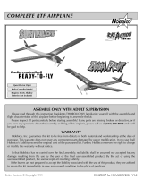
Requires 8 “AA” Alkaline
Batteries (not included)
Quiet Electric Flight
Radio-Controlled Model
Entire Contents © Copyright 2005 HCAZ3036 for HCAA1999, HCAA2010 V1.0
™
™
Instruction Manual

1. Your Hobbico Ventura
™
is not a toy, but rather a
sophisticated, working model that functions very much
like an actual airplane. Because of its realistic
performance, the Ventura, if not assembled and
operated correctly, could possibly cause injury to
yourself and spectators or damage property.
2. Assemble the plane according to the instructions. Do
not alter or modify the model. If you make any
modifications, you will void your warranty.
3. Testing has proven that the Ventura may be flown by
experienced pilots in winds of up to 15mph, but
beginners should fly the Ventura only when wind speeds
are 5mph or less. The Ventura should be flown only in
large, open areas free from trees, people, buildings,
telephone or electric lines or any other obstacles.
4. The Ventura RTF is offered on six different channels (1
through 6) that are on a “shared” frequency band of 27
MHz (mega Hertz). This means that both the Ventura
and ground-based models (cars and boats) may use
these channels. If two or more models are being
operated in the same area on the same channel, radio
interference may occur resulting in a crash of one or
both models. There is also a chance that someone at a
nearby R/C airplane flying site could be flying on the
same frequency as you. If this happens a crash may
result-with the person flying the more expensive
airplane suffering the greater loss (and having greater
potential for property damage or injury). To avoid
frequency conflicts look for other R/C activity at the
flying site you have chosen. If there is another R/C
model in the vicinity kindly ask the pilot/driver what is
his frequency. If you are on different frequencies you
may both confidently operate your models without fear
of a crash from radio interference. If you happen to be
on the same frequency you will have to take turns.
The best way to avoid radio interference (and to get
flight instruction) is to join an R/C club where frequency
control measures will be in effect. If you insist on flying
elsewhere, always be aware of your proximity to R/C
flying sites and other modelers who could be using the
same frequency as you.
If you’re an inexperienced modeler, we recommend
that you get assistance from an experienced,
knowledgeable modeler to help you with assembly and
your first flights. You’ll learn faster and avoid risking
your model before you’re truly ready to solo. Your local
hobby shop has information about flying clubs in your
area whose membership includes qualified instructors.
You can also contact the national Academy of Model
Aeronautics (AMA), which has more than 2,500
chartered clubs across the country. Through any one of
them, instructor training programs and insured
newcomer training are available. Contact the AMA at
the address or toll-free phone number below.
Academy of Model Aeronautics
5151 East Memorial Drive
Muncie, IN 47302
(800) 435-9262
Fax: (765) 741-0057
or via the internet at: http://www.modelaircraft.org
Attention: The Ventura is powered by a rechargeable
battery. At the end of the battery’s useful life, under
various state and local laws, it may be illegal to dispose
of the battery into the municipal waste system. Check
with your local solid waste officials for details in your
area for recycling options or proper disposal.
This product contains a chemical known to the state of
California to cause cancer and birth defects or other
reproductive harm.
PROTECT YOUR MODEL, YOURSELF
AND OTHERS.
FOLLOW THIS IMPORTANT SAFETY
PRECAUTION
2

Vertical Stabilizer (Fin): Vertical tail wing that stabilizes
the model in the “right/left” direction by keeping the tail
behind the nose.
Rudder: Movable surface connected to the fin. Controls
the turning direction of the model.
Horizontal Stabilizer (Stab): Horizontal tail wing that
stabilizes the model in the “up/down” direction.
Elevator: Movable surface connected to the stabilizer.
Controls the main wing angle to make the model climb
or descend.
Transmitter (Tx): Hand-held control box operated by
the pilot that sends signals to the receiver to control the
model for flying.
Receiver (Rx): Electronic unit in the airplane that
receives signals from the transmitter and relays them to
the servos to operate the controls.
Servo: An electronic unit inside the model with a small
motor, gears and an external arm that moves the
pushrod connected to the control surface (elevator and
rudder for the Ventura).
Electronic Speed Control (ESC) with Auto Cut-off: Electronic
unit in the airplane that controls the speed of the motor.
When the battery voltage drops to a certain point the
ESC will automatically cut off the motor, reserving
enough battery power to operate the radio while you
glide and land the airplane.
Trim Tabs: The sliding tabs on the transmitter that allow
fine adjustments of the control surfaces.
Volt (V): A Volt is a measure of a battery’s “muscle.” The
battery pack for your Ventura is made up of seven
individual 1.2V batteries. Connected together the total
voltage is 8.4 Volts (1.2 x 7).
Ampere (A): An Ampere, or “Amp,” is a measure of the
flow of electricity, or “current.” A milliamp (mA) is one
one-hundredth of an Amp.
Milliamp-Hours (mAh): Indicates the “size,” or capacity
of a battery pack (how much energy it can store). The
capacity of the Ventura’s battery is a 900 mAh (.9Ah), so
if the battery was connected to an electric motor that
required .9A to run, the battery could run the motor for
about one hour. However, at full power the Ventura’s
motor uses about 11 Amps, so it will run for about five
minutes on the 900 mAh battery (.9Ah battery/11A =
.082 hours (4.9 minutes).
Nickel-Metal Hydride (NiMH) Battery: There are a few
different types of rechargeable batteries. The Ventura
battery pack is a rechargeable NiMH battery. NiMH
batteries are lighter and smaller than most other types of
rechargeable batteries.
GLOSSARY
3

4
KIT INSPECTION
1
3
2
4
7
8
11
10
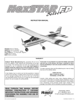
Kit Contents (RTF Version)
1. Fuselage (w/Preinstalled ESC)
2. Flag
3. 8.4V 900mAh NiMH Battery Pack
4. Transmitter
5. Spare Propeller, Spinner and Spinner Screw
6. Spare Fin Mounting Nuts
7. Charger
8. Wing
9. Fin with Fin Mounting Nuts
10. Stabilizer
11. Rubber Bands
Kit Contents (ARF Version)
1. Fuselage (w/Preinstalled ESC)
3. 8.4V 900mAh NiMH Battery Pack
5. Spare Propeller, Spinner and Spinner Screw
6. Spare Fin Mounting Nuts
7. Charger
8. Wing
9. Fin with Fin Mounting Nuts
10. Stabilizer
11. Rubber Bands
Note: Numbers not in numerical sequence to match
the RTF version photo above.
Before starting assembly, take an inventory of this kit to make sure it is complete, and inspect the parts to make
sure they are of acceptable quality. If any parts are missing or are not of acceptable quality, or if you need
assistance with assembly, contact Product Support. When reporting defective or missing parts, use the part names
exactly as they are written in the “Kit Contents” list on this page.
Hobbico Product Support:
3002 N Apollo Drive, Suite 1
Champaign, IL 61822
Telephone: (217) 398-8970 ext. 3
Fax: (217) 398-7721
E-mail: airsuppor
5
6
9

IMPORTANT: The Ventura manual has been written to
cover the ARF (Almost Ready to Fly) and the RTF (Ready
to Fly) versions of the aircraft. Certain steps and
instructions may not apply to your model. Please read
the manual completely prior to assembly.
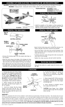
❏ 1. Unscrew the fin mounting nuts from the fin
mounting rods.
❏ 2. Join the fin to the top of the stab by inserting the
fin mounting rods all the way down into the holes while
holding the elevator in the full “up” position. (The
bottom of the stab is the side that doesn’t have the
stickers and has the control horn on the elevator.)
❏ 3. Insert the fin mounting rods all the way down
through the fuselage. Push down on the fin until there is
ASSEMBLY
FLYZONE 3-CHANNEL FM
TRANSMITTER (TX)
5

no gap between the fin and the stab and between the
stab and the fuselage. Install the fin mounting nuts until
they contact the fuselage. Then, tighten them three more
full turns. This will securely tighten the fin and stab
without overtightening.
❏ 1. Install two micro, or mini servos in the servo trays
as shown using the hardware provided by your radio
manufacturer.
❏ 2. Temporarily connect the servos to your receiver.
Center all trims on your transmitter and turn it on. Plug
the ESC into the throttle channel on your receiver and
then connect the battery to the ESC. This should center
the servos. Disconnect the battery from the ESC and turn
off your transmitter.
❏ 3. Attach servo arms to each servo, trimming as
necessary to allow both arms to travel freely. Insert the
elevator and rudder pushrods into the 2nd hole from
center as shown.
❏ 4. Ensure all servos are connected to the receiver and
mount the receiver as shown using hook and loop tape or
thick double sided tape. Route the antenna through the fuse
and out of the small hole in the tail of the Ventura.
❏ 5. Continue to “Radio Setup (RTF Version)” and
follow the instructions.
❏ 1. Install eight “AA” alkaline batteries in the back of
the transmitter and then replace the battery cover. Note:
Alkaline batteries are preferred over rechargeable
batteries because alkalines have a higher voltage.
RADIO SETUP (RTF VERSION)
RADIO SETUP (ARF VERSION)
FLIGHT PREPARATION
6

❏ 2. Center the elevator and rudder trim levers on
the transmitter. Move the elevator and rudder servo
reverse switches to the down position.
❏ 3. Move the throttle lever on the transmitter all the
way to the left (when viewing the transmitter from the
front), to the off position.
❏ 4. Switch on the transmitter. Check the battery
condition. Both the red and green lights should glow.
When the green light becomes dark the batteries are too
low and the model should not be flown. If the green
light becomes dark while flying, land the plane
immediately or loss of control may result.
❏ 5. Install the battery. Connect the battery to the plug
in the fuselage. Tuck in the wires so the hatch can close.
❏❏
6. See if the battery has any power by moving the
control stick on the transmitter and seeing if the servos
move. If the servos do not move, or if they stop
working while setting up the radio in the following
steps, disconnect the battery and refer to the “Battery
Charging” and “Battery Charging Safety Precautions”
sections on page 10.
❏ 7. Adjust the clevis on the end of the elevator
pushrod so that when connected to the outer hole in the
elevator control horn, the elevator will be centered.
Connect the clevis to the elevator horn and pinch it
together until the pin in the clevis snaps in.
IMPORTANT!!! ALWAYS reduce the throttle lever
and turn on the transmitter before plugging in the
battery. Similarly, NEVER plug in the battery before
reducing the throttle lever and turning on the
transmitter.
7

❏8. Adjust the clevis on the end of the rudder pushrod
so that when connected to the outer hole in the rudder
control horn, the rudder will be centered. Connect the
clevis to the rudder horn and pinch it together until the
pin in the clevis snaps in.
❏ 9. Move the elevator using the control stick on the
transmitter. Make certain that the elevator responds in
the correct direction: Moving the stick downward
(pulling it back) should make the elevator move up. In
flight, this will lower the tail to raise the angle of the
wing, making the model climb. Pushing the elevator
stick forward will have the opposite effect. If the
elevator does not respond in the correct direction,
check the elevator servo reverse switch on the front of
the transmitter.
❏ 10. Move the rudder using the control stick and
make certain the rudder responds in the correct
direction: Moving the stick to the right should make the
rudder move right. In flight, this will make the model
turn right. Moving the stick to the left will make the
model turn left. If the rudder does not respond in the
correct direction, check the rudder servo reverse switch
on the front of the transmitter.
Note: Beginners should connect the clevises to the
outer holes in the control horns as shown in steps 7
and 8. When the clevises and pushrods are
connected to the outer holes the elevator and rudder
will have less movement, or “throw.” This will allow
the Ventura to fly smoother and more docile so
beginners will be less likely to over control the model
when learning to fly.
8

Now it’s time to check the motor operation. Use caution
and always beware of the spinning propeller. Even
though the Ventura is a small, electric-powered model
airplane, the propeller turns at a high RPM and could
cause bodily harm.
❏ 11. Securely hold the model. Make sure the throttle
lever on the back of the transmitter is in the off position
all the way to the left. Press the red motor start button.
Carefully advance the throttle lever and observe that the
propeller will turn. The more you advance the throttle
lever, the faster the motor will turn until it reaches full
power. Return the throttle lever to the off position.
Now the controls are set. Disconnect the battery and
turn off the transmitter. Note: There is no on/off switch
on the airplane, so whenever the battery is connected
the airplane is “on.” Therefore, the battery should
always be disconnected when the model is not in flight.
❏ Use a fine-point felt-tip pen to write your name,
telephone number and address directly on the model, or
write it on a piece of masking tape and apply it to
the model.
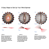
❏ 1. Use a fine-point felt-tip pen to mark the balance
range on both sides of the bottom of the wing according
to the measurements shown in the photo. Note that the
measurements are from the front, or leading edge of
the wing.
❏2. Install the battery (it is not necessary to hook it up).
❏ 3. Mount the wing to the fuselage with two
rubber bands.
BALANCE YOUR MODEL
IDENTIFY YOUR MODEL
PREFLIGHT
9

❏ 4. Lift the model with your fingertips between the
lines under the wing. Position your fingertips where
necessary to get the model to sit level, or “balance.” If
your fingertips are between the lines, the Ventura
balances and is ready to fly.
❏ If the model balances with your fingertips ahead of
the lines, weight will have to be added to the tail to get
it to balance. Tail weight may be stuck to the side of the
fuselage or to the bottom of the stabilizer.
❏If the model balances with your fingertips behind the
lines, weight will have to be added to the nose to get the
model to balance. Stick-on lead weight may be
purchased from the hobby shop. Nose-weight may be
stuck to the inside of the hatch.
❏ 5. Stick on as much weight as required to get the
model to balance when lifted by your fingers between
the lines. If you added any weight, recheck the balance.
❏ 1. The battery should always be discharged before
charging. If the battery is not discharged, a 30-minute
charge will overcharge the battery. If it has been a while
since you last flew your Ventura, or if for any other
reason you do not remember how much “charge” is left
in the battery, it should first be discharged before
charging. To discharge the battery, install and connect it
to the model. Turn on the transmitter and run the motor
until it stops and the battery has been discharged. Now
the battery is ready to be charged.
❏ 2. Never charge the battery while the car engine is
running. This will increase the output of the charger and
overcharge your battery.
❏ 3. Always place the batteries and charger outside
the car while charging.
❏4. Frequently touch or handle the battery to monitor
its temperature while charging. Use caution while
touching the battery as it could become hot if
overcharged. It is okay and normal for the battery to be
warm to the touch, but never allow it to become hot. If
the battery has become hot it is overcharged and should
be disconnected from the charger immediately.
❏ 5. Never leave a charging battery unattended.
Warning: DO NOT overcharge the battery! Unless
you have just completed a flight and run the battery
all the way down, there is no way to know how much
charge is left. Overcharging the battery may result in
melting the plastic cover, damaging the vehicle, or
causing the battery to explode.
BATTERY CHARGING SAFETY
PRECAUTIONS
WARNING: Before charging the battery you must
read and follow ALL of the Battery Charging Safety
Precautions and the Battery Charging Instructions.
BATTERY CHARGING
10

❏ 6. If you ever use a different battery charger, charge
this battery pack only at a maximum charge rate of 750
mA. A higher charge rate will charge the battery pack
too quickly and heat up the wires.
❏ 7. A properly cared for battery pack will last a long
time. If the battery pack is continually overcharged or
charged at too high of a rate, the life of the battery pack
will be shortened.
❏ 8. After each flight, remove the battery pack from the
airplane and allow it to cool completely before recharging.
❏ 1. Discharge the battery by installing it in the model
and running the motor until it stops.
❏ 2. Set the Voltage switch on the charger to the 8.4V
setting all the way over to the left.
❏3. Connect the battery charger to a 12-volt accessory
socket (cigarette lighter) in a vehicle. The vehicle’s
engine must not be running. Place the charger outside
the vehicle. Do not let the battery or charger hang by
the wires. If necessary, place the charger and battery on
a stand.
❏4. Connect the battery pack to the charger. Note: The
connectors will plug in only one way.
❏ 5. Rotate the timer dial to 30 minutes. The red light
on the charger will illuminate when the battery is
charging. If the red light does not illuminate, check the
connection between the charger and the 12-volt
accessory socket (cigarette lighter) output and between
the charger and the battery.
WARNING! NEVER LEAVE A CHARGING BATTERY
UNATTENDED.
❏6. During charging, periodically feel the battery to see if
it is becoming warm. A warm (but not hot) battery pack is a
sign that it is fully charged. Once the pack is warm,
disconnect it from the charger. Depending on how much
charge was already in the pack, you may have to disconnect
the battery before the 30 minutes are up.
❏ 7. When the timer dial has returned to “0”
disconnect the battery from the charger and disconnect
the charger from the vehicle.
Though the Ventura is a “Park Flyer,” the best place to fly any
model is at an AMA chartered club field. The AMA address
and telephone number are on page 2.
If not flying at a model airplane flying site, find an area
clear of trees, power lines and other structures. Do not
fly within 6 miles of existing R/C flying fields or around
groups of people–especially children.
Review these flying procedures so you will have an idea
of what to expect when you meet your instructor.
Place the wing on the fuselage. Center the wing from
side-to-side, aligning the arrows with the seam on the
MOUNT THE WING
FLYING
IMPORTANT!!! When flying at a radio control model
airplane club flying site, never turn on the transmitter
until you have the matching frequency pin in your
possession indicating that there is no one else flying
on your frequency.
FIND A SUITABLE FLYING SITE
BATTERY CHARGING INSTRUCTIONS
11

top of the fuselage. First secure the wing with two
rubber bands–one on each side, then with two more
rubber bands in a crisscross fashion.
Tie the red ribbon to the tip of the transmitter antenna. This
will serve as a wind flag to indicate the wind direction.
Don’t forget to scan the area for other modelers who
may be operating R/C models that may be on the same
frequency as you.
Fully extend the transmitter antenna. Make sure the
throttle lever is in the off position and then turn on the
transmitter. Install the battery; then plug it in. Be careful
not to inadvertently bump the motor start button.
Check the controls before every flight by moving the
control stick in all directions, observing how the
controls react, and making sure they respond in the
correct direction. Most malfunctions can be discovered
by performing this simple, last-second procedure,
saving your model from a crash.
Perform a range check before each flying session of the
day. Do not push the motor start button during the first
range check. With the antenna collapsed, walk 50 feet
[15m] from the airplane. Move the rudder and elevator
control stick, making sure the controls respond. Have an
assistant hold the airplane and press the motor start button
to start the motor. Perform the range test with the motor
running. The controls should respond as expected. If there
are any “glitches” or unexpected control movements, the
plane is not safe to fly. Make sure the transmitter batteries
are in good condition and make sure the motor battery in
the plane is adequately charged.
Extend the transmitter antenna. Do not press the motor
start button until you are actually ready to launch the
airplane. Scan the area one last time to make certain
there are no spectators, or that any spectators present
are standing behind you.
Hold the transmitter in your left hand and hold the
airplane in your right hand (or better, have your assistant
launch the model). When ready to launch, raise the
model over your head and point the nose directly into
the wind. Press the motor start switch, fully advance the
throttle, then toss the model into the air at a level, or
slightly nose up attitude. Make sure you launch with the
wings level. Note: A good launch is important–it would
be better to gently toss the model rather than throw it
into the air at a bad angle that will make recovery
difficult. Be careful on your first launch and make sure
you get it going straight ahead and into the wind.
Immediately transfer your right hand to the transmitter
so you can operate the control stick. Use the control
stick to steer the Ventura straight ahead while
establishing a gradual climb.
When you get to a comfortable altitude make your first
turn AWAY from yourself and any spectators that may
be present. Generally (but not always), slight “back
pressure,” or “up” elevator will be required to maintain
altitude during turns.
Caution: It is likely that the Ventura will not fly
straight ahead on the first launch. It may suddenly
dive or climb or turn to the right or the left. This is
impossible to predict because the model has not yet
been adjusted, or “trimmed” for straight-and-level
flight. Even though the controls were centered
visually at home, minor trim adjustments will
probably still be required to get the model to fly
straight. This means you will have to be ready on the
control stick to give corrections immediately after
launching. Instructions are provided for how to trim
the model after it has reached a comfortable altitude,
but until then continual control stick input may be
required. After the model has been trimmed it should
fly straight-and-level on its own–this will make the
next hand launch easier. Just remember to be ready to
give immediate control stick inputs after launching.
TAKEOFF
CHECK THE CONTROLS
OPTIONAL: INSTALL THE WIND FLAG
12

Here are a few things to keep in mind while flying
your Ventura:
1. Don’t let it fly too far away. The farther away, the
harder it will be to see what the Ventura is doing and
give the correct control inputs to fly it back.
2. When learning, it is best to keep the plane high
enough so that if you make a mistake, you have enough
altitude to make corrections.
Your first objectives will be to gain altitude (so you will
have time to think and react) and make the first turn (so
the model does not get too far away). When the plane is
flying away from you, the Ventura will respond the way
you would expect; moving the rudder stick to the right
will make the plane turn to your right. When the Ventura
is flying toward you it appears to respond in the
opposite direction, but in actuality it is responding the
same way; moving the rudder stick to the right will still
make the plane turn to its right, but when it is facing you
it will turn to your left. Beginning modelers can avoid
this initial disorientation by turning their body away
from the model and holding the transmitter so they are
facing the same direction that it is flying. In this case
you will have to look over your shoulder until the model
passes by.
The next objective is to trim the plane for straight-and-
level flight. With the Ventura flying directly into the
wind, see what it does when you let go of the control
stick. It should fly straight-and-level. If the Ventura
climbs, it will need some down trim. Push the elevator
trim tab forward (giving it down trim) until the Ventura
flies level. Do the opposite if the Ventura dives when the
control stick is released. If the plane turns to the left
when the control stick is released, move the rudder trim
tab to the right until it flies straight, and vice versa.
Continue to adjust the trims so the Ventura will fly
straight when going into the wind.
The last exercise for your first flight will be to turn off the
motor and see how the Ventura reacts so you will know
what to expect when it’s actually time to land. Again,
flying into the wind, reduce the throttle and observe
how your Ventura reacts. It should just glide straight
ahead and establish a gentle nose-down attitude. Allow
the model to glide as long and far as you like–you can
even execute turns. When ready, apply full power and
regain altitude. Do this a few times to get used to power-
off flight.
Remember, the Ventura is a “motor glider,” so you can
turn off the motor at any time. In fact, flying with the
motor off is the best way to extend flight time. Use full
power to climb to a high altitude, then shut the motor
off and glide. When you’ve lost too much altitude apply
power and climb back into the sky. In conditions where
there is no rising air, flight times of 8 to 11 minutes
should be possible. When there is rising air, or “lift,”
indefinite flight times are possible.
Attempt a few practice landing approaches before the
battery discharges so you can see what it will be like to
land–without actually doing so. This is done by cutting
the power, allowing the Ventura to lose altitude and
gliding it by in front of you five or so feet [1.5m] above
the ground. After it gets too low add full power, climb
out and go around again. This will give you an
indication of what to expect, how to line it up with your
landing spot and how much room it will take to land.
When you are ready to do a practice landing cut the
power when the model is flying down wind (with the
wind) in front of you. Make a turn into the wind
allowing the Ventura to lose altitude. Be ready to apply
power if you get too far away or too close to the ground.
You can always apply power, then cut power as needed
to bring it closer in. Allow the Ventura to glide by about
ten feet [3m] in front of you. When it gets too low or
after it goes by add power and do it again. When you
are ready to actually land do the same thing, only this
time simply don’t add power. As the Ventura gets closer
to the ground apply more and more “up” elevator until
it slows to a stop–right on the ground. The propeller will
fold back preventing damage.
Retrieve the model and make a post-flight inspection by
looking at the propeller, wings and tail for any damage.
If any elevator trim was required, take a look at the
elevator and make a mental note of its position. With
the transmitter on and the battery plugged in, remove
the elevator clevis from the control horn, return the
elevator trim tab to center, then turn the clevis in or out
until the elevator will be in the same position it was
before you disconnected the clevis. Connect the clevis.
AFTER FLIGHT
LANDING
FLIGHT
13

Perform the same operation for the rudder. The objective
is to have the model fly straight-and-level with the
trims centered.
Unplug the battery and then turn the transmitter off.
Remove the battery and allow it to cool before recharging.
Allow the motor to cool before the next flight.
Caution: If the propeller is ever stuck and cannot rotate
when power is applied, the battery and speed controller
will overheat. Immediately cut the throttle lever to stop
the motor. If you fail to do this, the motor, speed control
and/or battery will be damaged.
In the hands of intermediate or advanced pilots the
Ventura is capable of aerobatics. Among many thrilling
maneuvers, stall turns and loops are fairly easy and fun.
When ready to attempt aerobatics, you may move the
clevis inward on the control horns. The closer in on the
control horns that the clevises are, the more control
throw the control surfaces will have and the more
aerobatic the Ventura will be. The middle holes are for
intermediate pilots. Advanced pilots may fly the Ventura
with the clevises in the innermost holes.
Beginners should not attempt aerobatics until…they are
no longer beginners and are able to react quickly and
get the model out of adverse situations or avoid adverse
situations altogether!
Stall Turn: First attempts at stall turns should be initiated
with plenty of altitude and with the wind, so that the
maneuver finishes into the wind. Stall turns are best done
off to the left or right of the pilot. Fly the model straight-
and-level under full power. Pull elevator until the model is
vertical. Allow the model to climb vertically while
reducing power to half-throttle. Just before the model
stops its vertical ascent, apply full left rudder until the
model pivots around the wing and is now pointing
downward. Continue the vertical dive until the Ventura
has gained enough speed to level out and re-enter straight-
and-level flight as you apply full power.
Loop: Loops should always be done into the wind. A
proper loop should be done on-center, in front of the
pilot. Fly straight-and-level under full power. Gradually
pull up elevator, allowing the model to perform the
loop. After the model passes through the top of the loop
reduce power. As the model completes the loop apply
full power and relax the elevator to return the model to
straight-and-level flight.
AEROBATICS
14

Minor damage to the wing and tail parts can be repaired
with epoxy. Use tape to hold the parts together while
the epoxy hardens.
Do not attempt to repair a damaged propeller. Minor
chips or scratches to the tips of the propeller are
acceptable, but performance may be reduced. If the
propeller ever suffers major damage such as cracks near
the base of the blade, the propeller must be replaced. To
replace the propeller use a small Phillips screwdriver to
remove the spinner, then loosen the screws in the hub.
Replace the propeller and hub, tighten the screws, then
replace the spinner. Be certain the spinner and propeller
hub can spin freely and are not contacting the fuselage.
Replacement parts for the Hobbico Ventura are available
using the order numbers in the “Replacement Parts List”
shown at the right. The fastest, most economical service
can be provided by your hobby dealer or mail-order
company. Parts may also be ordered directly from Hobby
Services, but full retail prices and shipping and handling
charges will apply. Illinois and Nevada residents will also
be charged sales tax.
To locate a hobby dealer, visit the Hobbico web site at
www
.hobbico.com. Choose “Where to Buy” at the
bottom of the menu on the left side of the page. Follow
the instructions provided on the page to locate a U.S.,
Canadian or International dealer. If a hobby shop is not
available, replacement parts may also be ordered from
Tower Hobbies at www
.to
werhobbies.com, or by
calling toll free (800) 637-6050.
Parts may also be ordered directly from Hobby Services
by calling (217) 398-0007, or via facsimile at (217)
398-7721, but full retail prices and shipping and
handling charges will apply. Illinois and Nevada
residents will also be charged sales tax. If ordering via
fax, include a Visa
®
or MasterCard
®
number and
expiration date for payment.
Mail parts orders and payments by personal check to:
Hobby Services
3002 N Apollo Drive, Suite 1
Champaign IL 61822
Be certain to specify the order number exactly as listed
in the Replacement Parts List. Payment by credit card or
personal check only; no C.O.D. If additional assistance
is required for any reason contact Product Support by
, or by
telephone at (217) 398-8970.
How to Purchase:
Missing Pieces Contact Product Support
Instruction Manual Contact Product Support
Order Number Description
HCAA3268 Wing
HCAA3267 Stab, fin and fin mounting nuts
HCAA3496 Canopy
HCAQ3482 Propeller and spinner
HCAM7034 Electronic speed control
HCAA3497 Fuselage
HCAA3457 Decal set
HCAG3478 Motor
HCAP9915 Battery charger
HCAM7112 8.4V 900mAh NiMH battery
HCAA3266 Clevis/Control Horns (2 sets)
REPLACEMENT PARTS LIST
ORDERING REPLACEMENT PARTS
REPAIRS
15

BUILDING NOTES
Kit Purchased Date: _____________________
Where Purchased: ______________________
Date Assembly Started: __________________
Date Assembly Finished: ________________
Finished Weight: ______________________
Date of First Flight: ____________________
FLIGHT LOG
/