CTC Union ET100A User manual
- Category
- Network switches
- Type
- User manual
This manual is also suitable for

ET100/G64
Synchronous WAN Ethernet Bridge
10/100Base-TX Ethernet
over G.703 64K Co-directional


CTC Union Technologies Co., Ltd.
Neihu Technology Park
8F, No. 60 Zhouzi Street.
Neihu District, Taipei, 114
Taiwan
ET100/G64 Ethernet WAN Bridge, User Manual
Version 1.0 Nov. 4, 2008 Release
Version 1.1 Jul. 21, 2009 Update
This manual supports the following models:
ET100/G64 Ethernet WAN Bridge
All specifications subject to change without notice.

LEGAL
The information in this publication has been carefully checked and is believed to be entirely accurate at
the time of publication. CTC Union Technologies assumes no responsibility, however, for possible errors
or omissions, or for any consequences resulting from the use of the information contained herein. CTC
Union Technologies reserves the right to make changes in its products or product specifications with the
intent to improve function or design at any time and without notice and is not required to update this
documentation to reflect such changes.
CTC Union Technologies makes no warranty, representation, or guarantee regarding the suitability of its
products for any particular purpose, nor does CTC Union assume any liability arising out of the
application or use of any product and specifically disclaims any and all liability, including without
limitation any consequential or incidental damages.
CTC Union products are not designed, intended, or authorized for use in systems or applications intended
to support or sustain life, or for any other application in which the failure of the product could create a
situation where personal injury or death may occur. Should the Buyer purchase or use a CTC Union
product for any such unintended or unauthorized application, the Buyer shall indemnify and hold CTC
Union Technologies and its officers, employees, subsidiaries, affiliates, and distributors harmless against
all claims, costs, damages, expenses, and reasonable attorney fees arising out of, either directly or
indirectly, any claim of personal injury or death that may be associated with such unintended or
unauthorized use, even if such claim alleges that CTC Union Technologies was negligent regarding the
design or manufacture of said product.
TRADEMARKS
Microsoft is a registered trademark of Microsoft Corp.
HyperTerminal™ is a registered trademark of Hilgraeve Inc.
User Manual
Version 1.0 November 2008 Release
This manual supports the following:
ET100/G64 -AC
ET100/G64 -DC
This document is the first official release manual. Please check CTC Union's website for any updated
manual or contact us by E-mail at [email protected]. Please address any comments for improving this
manual or to point out omissions or errors to [email protected]. Thank you.
CTC Union maintains a support web site (support.ctcu.com) where you may obtain the latest manual,
quick installation guide, and operational firmware. Membership to this web site is free, however, you must
be a registered member in order to access any software updates.
CTC Union Technologies Co., Ltd.
2008-2009 Copyright, All rights reserved.

Table of Contents
i
1.0 Overview................................................................................................................................................. 7
1.1 Features................................................................................................................................................... 7
1.2 Specifications.......................................................................................................................................... 7
1.3 Functional Block Diagram...................................................................................................................... 9
1.4 Unit Detail............................................................................................................................................. 10
1.5 Theory of Operation.............................................................................................................................. 12
1.6 DIP Switch Setting Tables: ................................................................................................................... 13
1.6.1 Data Rate Settings:......................................................................................................................... 13
1.6.2 Interface Settings: .......................................................................................................................... 13
1.6.3 LAN Bridge Settings:..................................................................................................................... 13
1.7 Clocking Examples............................................................................................................................... 14

Table of Contents
ii
This page left blank intentionally.

ET100/G64 LAN-WAN Bridge
7
1.0 Overview
The ET100/G64 Network Bridge is a high performance, remote, self-learning Ethernet bridge. Its
solid design makes it ideal for cost-sensitive bridging applications, or as a LAN extender or segmenter
over G.703 64K Co-directional bit stream type infrastructures.
1.1 Features
10BASE-T/100BASE-TX, Auto, Full Duplex or Half Duplex
HP Auto-MDI/MDIX detects and corrects crossed cable
IEEE 802.3x flow control enable/disable
Real-time filtering with 256 MAC address table
Automatic address learning, aging and deletion after 5 minutes
Up to 340 packet-buffering capacity
Forwarding and filtering rate at wire speed with throughput latency of 1 frame.
Auto padding of undersized packets to meet the minimum Ethernet packet size requirement
Buffering modes can be selected according to the setting of WAN and LAN line speeds
Built-in 64K timing clock generator for WAN link
1.2 Specifications
LAN
Standard Fully compliant with IEEE 802.3/802.3u
Connector Shielded RJ-45
Speeds 10BASE-T/100BASE-TX, Auto, Full or Half Duplex
Frames Supports 64 to 1536 byte packet lengths (supports 802.1Q pass through)
WAN
Interface Fixed type ITU-T G.703 64K co-directional interface
Data Rate 64Kbps
Clock Source Tx/Rx internal, Tx/Rx external or recovery from co-directional data
Line 4 wires, 0.5 -0.7mm twisted pair cable
Range Up to 800m over 24AWG cable or better
Impedance 120 Ohms
"Pulse" amplitude 1.0V Nominal ± 0.1V
"Zero" amplitude 0V Nominal ± 0.1V
Single pulse width 3.9us
Double pulse width 7.8us
Clock frequency 64Kbps ± 100ppm.
Interface connector RJ-48C.
Complies with ITU-T G.703 and G.823.
Frame format Unframed only.
Line code 64Kbps co-directional line code.
Ethernet Bridge
Protocol Synchronous HDLC (ISO 13239)
Bridge Address learning, aging and deletion after 5 minutes
MAC Table 256 addresses
Buffer 340 packet buffer
General
Power AC model: Built-in AC Switching Power, 90~250VAC, 47~63Hz
DC model: Built-in DC to DC, 18~72VDC
Consumption less than 5 watts
Environment Temperature: 0~50
o
C (32~125F)
Humidity: <90% non-condensing
Dimensions 235(L) x 195(W) x 45(H) mm (10.25" L x 7.675" W x 1.75" H)
Weight 825g (1.8 lb.) net

ET100/G64 LAN-WAN Bridge
LED Indicators
PWR Green ON Power ON
OFF Power OFF
TD Green ON Codirectional transmit data is mark “1”
OFF Codirectional transmit data is space “0”
Flash Codirectional transmit data is changed
RD Green ON Codirectional receive data is mark “1”
OFF Codirectional receive data is space “0”
Flash Codirectional receive data is changed
LINK Green ON Ethernet link
OFF Ethernet no link
Receive Green OFF No LAN receive event
ON LAN receive event
Transmit Green OFF No LAN transmit event
ON LAN transmit event
100M Green OFF 10Base-T
ON 100Base-TX
Full Green OFF Half duplex
ON Full duplex
Error Red OFF No LAN error event
ON LAN error event
Test Red OFF No loop back
ON Loop back enable
Loop back
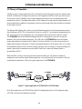
When the Loop back push-button switch is depressed, Received timing and data are looped back out the Transmit
timing and data interfaces.
Co-directional
TX-
RX-
TX+
RX+
Figure 1. ET100/G64 Loop back paths
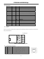
Co-directional Pin Assignment
Pin Designation Description
1 RxRing Receive signal with negative polarity
2 RxTip Receive signal with positive polarity
4 TxRing Transmit signal with negative polarity
5 TxTip Transmit signal with positive polarity
7 FG Connects to frame ground
8 FG Connects to frame ground
8

ET100/G64 LAN-WAN Bridge
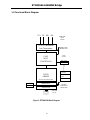
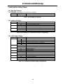
1.3 Functional Block Diagram
9
Clock
Generator
SYNC
SPEED
N64K
G.703 Co-directional
Line Transceivers
Figure 2: ET100/G64 Block Diagram
SYNC
HDLC
CONTROLLER
Full Du
p
lex
Half Du
p
lex
Ext. clock
Int. clock
FILTER
ENGINE
plus 256 MAC Address Table
WAN SIDE
RJ-45
Female
LAN SIDE
RJ-45
Clock
Source
IEEE802.3u I/F
Link LED
LAN Tx LED
LAN Rx LED
WAN Tx LED
WAN Rx LED
Auto-MDIX Phy
TX+ TX- RX+ RX-

ET100/G64 LAN-WAN Bridge
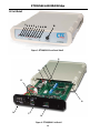
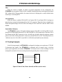
1.4 Unit Detail
1 1
2 2
3 3
4
10
15
19
16
11
17
18
12
13
14
5
6
7
8
9
10
4
11 11
5
6
7
8
9
10
Figure 3: ET100/G64 Front Panel Detail
Figure 4. ET100/G64 Unit Detail

ET100/G64 LAN-WAN Bridge
11
(1) PWR LED
Green on, when external power adapter is plugged in and AC power is supplied to it.
(2) G.703 TD LED:
Green, on or flashing indicates receiving data on the G.703 co-directional interface.
(3) G.703 RD LED:
Green, on or flashing indicates transmitting data on the G.703 co-directional interface.
(4) Ethernet Link LED:
Green, indicates the Ethernet has a link to an external device.
(5) Ethernet Receive LED:
Green, flashes to indicate reception from the LAN.
(6) Ethernet Transmit LED:
Green, flashes to indicate transmission to the LAN.
(7) Ethernet 100M (Speed) LED
Green, on indicates the Ethernet is connected at 100M speed (Off is 10M speed)
(8) Ethernet Full (Duplex) LED
Green, on indicates the Ethernet is connected in Full Duplex (Off is Half Duplex)
(9) Ethernet Error LED
Red, when on, indicates an error condition on the Ethernet interface
(10) Test LED
Red, when on, indicated that the Loop back test is active
(11) Loop back
This pushbutton switch is used to initiate co-directional loopback towards the remotely connected device.
(12) SW2, configuration DIP switch (refer to setting tables)
(13) SW3, configuration DIP switch (refer to setting tables)
(14) SW4, configuration DIP switch (refer to setting tables)
(15) Power Switch, This toggle switch makes or breaks the power connection to the internal electronics
(16) Power Input:
This connector depends on the model, AC or DC. AC model uses IEC connector, while DC has a 3
pin terminal block for power connections.
(17) RJ-45 Ethernet LAN Port:
This is an auto-MDI/MDIX port for connection to the LAN.
(18) G.703 64K CO (RJ-48C)
(19) Card alignment slot molded into the housing

ET100/G64 LAN-WAN Bridge
1.5 Theory of Operation
A bridge is used to connect networks locally or remotely such that they appear to the user to be the same
network. An Ethernet LAN bridge will connect two LAN segments at the Data Link Layer (ISO Layer 2).
At this layer, the MAC (Media Access Control) addresses are used for low level addressing to send
information to devices. The bridge builds tables of MAC addresses for each network segment based on the
source and destination addresses of the packets it receives and forwards, then filters the traffic not destined
for the remote network.
The Ethernet-WAN bridge will connect two remote Ethernet networks over bit stream interfaces such as
that of modems or DSU/CSUs. One method to do this is to use HDLC, an international standard set by the
ISO, a set of protocols for carrying data over a link with error detection/correction and flow control.
The ET100/G64 utilizes both Ethernet Bridging and HDLC encapsulation to provide a connection
between LANs over bit stream architectures. The LAN side of the ET100/G64 receives an Ethernet
packet and examines its destination MAC address. If it knows the MAC is on the local network then it
simply drops the packet. Otherwise, if it knows the packet destination is on the remote side, or if it cannot
be determined because its MAC cannot be found in the table, then it forwards it. During forwarding, the
packet is processed for transmission across the WAN link. Here is where the Ethernet packet is
encapsulated in HDLC.
When the HDLC packet is received on the remote side unit's data port, the packet is checked for
transmission errors, and the original Ethernet packet(s) is recovered and sent out the remote's LAN port
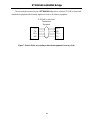
completing the transmission. Here is the typical application of the ET100/G64.
Figure 5. Typical application of ET100/G64 LAN-WAN Bridge.
In the above application, the ET100/G64 provides LAN bridging between two LAN segments using a
G.703 64K co-directional transmission network.
12

ET100/G64 LAN-WAN Bridge
13
1.6 DIP Switch Setting Tables:
1.6.1 Data Rate Settings:
The ET100/G64 is designed for a fixed data rate of 64Kbps.
SW2 SW STATE Function
1-8 Reserved
Table 1: DIP settings for Data Rate.
1.6.2 Interface Settings:
SW3 SW STATE Function
OFF Timing recovered from received data on codirectional interface
1
ON Timing from Internal 64KHz oscillator
OFF AIS is disabled (default)
2
ON Transmit AIS [all 1's] when receive signal is lost
OFF Transmit Octal code violation (default)
3
ON Transmit without code violation
4-8 Reserved
Table 2: DIP settings for Co-directional Interface Configuration.
1.6.3 LAN Bridge Settings:
SW4 SW STATE Function
-1 -2 Memory Buffer configuration
OFF OFF LAN to WAN 308 packets, WAN to LAN 32 packets (default)
OFF ON LAN to WAN 170 packets, WAN to LAN 170 packets
ON OFF LAN to WAN 32 packets, WAN to LAN 308 packets
-1,-2
ON ON Reserved
OFF MDI [1:1 to HUB]
-3
ON Auto MDIX (default)
OFF Ethernet Speed 100Base-TX
-4
ON Ethernet Speed 10Base-T
OFF Ethernet Full Duplex
-5
ON Ethernet Half Duplex
OFF Nway Enable [ignore 4&5] (default)
-6
ON Nway Disable [follow 4&5, MDI-X is disabled]
OFF 802.3X Flow control disable (default)
-7
ON 802.3X Flow control enable
OFF Filter Disable [Transparent forwarding] (default)
-8
ON Filter Enable [Bridge mode]
Table 3: DIP settings for Ethernet Bridge Configuration.

ET100/G64 LAN-WAN Bridge
Filter:
When this feature is disabled, all frames are passed transparently. In this configuration, the
ET100/G64 acts as a repeater. When the filter is enabled, frame destinations are tested against the internal
MAC address table. Filtering enabled is the normal selection for Bridging but is usually disabled when
connecting to a switching HUB.
Auto-negotiation:
When this feature is enabled (SW4-6=OFF), the Duplex (SW4-5) and Speed (SW4-4) settings are
ignored and are automatically determined from the LAN connection. When this feature is disabled, the
Duplex and Speed settings of the LAN follow the settings of SW4-4 and SW4-5 and auto MDIX will be
disabled.
Packet Buffer Utilization:
The ET100/G64 contains a 340 packet buffering capacity. When SW4-1 is OFF and SW4-2 is ON,
this buffer is divided equally between LAN to WAN and WAN to LAN packet traffic. When the LAN is
Fast Ethernet and the WAN connection is slow, the buffer may be better utilized by applying a greater
portion to the LAN to WAN packet traffic. In this case, set both SW4-1&2 to OFF. This will provide a 9 to
1 buffer division for LAN to WAN versus WAN to LAN buffer and should increase utilization.
1.7 Clocking Examples
In the following example, the ET100/G64 is configured for bridging over synchronous G.703 64K
Co-directional data signals. One ET100/G64 is configured with an internal clock to facilitate
point-to-point application with another ET100/G64. The internal clock is fixed at 64Kbps. The unit
configured for external clock receives timing from the unit providing the co-directional clock.
TD+
TD-
RD+
RD-
RD+
RD-
TD+
TD-
Internal CO Receive
Figure 6: Point to Point, Master (internal) and Slave (receive clock)
14

ET100/G64 LAN-WAN Bridge
The next example connects the pair of ET100/G64 bridge units to existing G.703 64K co-directional
transmission equipment which already supplies the clock to the tributary equipment.
G.703 64K co-directional
Transmission
Equipment
TD+
TD-
RD+
RD-
RD+
RD-
TD+
TD-
64K Receive 64K Receive
Figure 7: Point to Point, over existing co-directional equipment (recovery clock)
15

ET100/G64 LAN-WAN Bridge
16

CTC Union Technologies Inc
Fax:(886)2 27991355
Tel:(886)2 26591021
Attn : Technical Support Department
E-mail:[email protected]
From Company:
Name:
Tel: ( )
Fax:( )
MODEL: ET100/G64
ACTIVITY: As attached in DIP switch setting table
SYS CONFIGURATION:
Question

Technical Inquiry Form
MODEL No.: ET100/G64
Please fill in the DIP switches configuration with '9' marks into the following table. Send it to us by fax, and we will reply to you
immediately.
Your Setting CTC Suggestion
SW NO.
DIP
FUNCTION
ON OFF ON OFF
SW1 na Loop Back X
SW2 1-8 reserved
SW3 1 Tx Timing Setting X
SW3 2 AIS X
SW3 3 Octal Code Violation X
SW3 4-8 Reserved
SW4 1 Bridge Buffer Conf. X
SW4 2 Bridge Buffer Conf. X
SW4 3 MDIX Setting X
SW4 4 10 / 100Base manual X
SW4 5 Full / Half Duplex manual X
SW4 6 auto negotiation / manual X
SW4 7 802.3x Flow Control l X
SW4 8 Bridge Filter X
Additional comments/questions:


-
 1
1
-
 2
2
-
 3
3
-
 4
4
-
 5
5
-
 6
6
-
 7
7
-
 8
8
-
 9
9
-
 10
10
-
 11
11
-
 12
12
-
 13
13
-
 14
14
-
 15
15
-
 16
16
-
 17
17
-
 18
18
-
 19
19
-
 20
20


CTC Union ET100A User manual
- Category
- Network switches
- Type
- User manual
- This manual is also suitable for
Ask a question and I''ll find the answer in the document
Finding information in a document is now easier with AI
Related papers
-
CTC Union ETU011U User manual
-
-
-
-
-
-
-
-
-
Other documents
-
Nokia 100Base-T User manual
-
 3One data 7212 User manual
-
Jones Stephens G60300 Installation guide
-
Intellisystem IT-7210-PC Owner's manual
-
Trendnet TU2ET100 User manual
-
Trendnet TU2-ET100 User guide
-
Patton electronic 2701/I User manual
-
 LDARC ET125 V2 User manual
-
-

