Page is loading ...

instruction manual
To u c h Pa n e l s a n d A c c e s s o r i e s
8.5" Color Passive
LCD Touch Panels
(Firmware version G3 or higher)

AMX Limited Warranty and Disclaimer
AMX Corporation warrants its products to be free of defects in material and workmanship under normal use for
three (3) years from the date of purchase from AMX Corporation, with the following exceptions:
• Electroluminescent and LCD Control Panels are warranted for three (3) years, except for the display and touch
overlay components that are warranted for a period of one (1) year.
• Disk drive mechanisms, pan/tilt heads, power supplies, MX Series products, and KC Series products are
warranted for a period of one (1) year.
• Unless otherwise specified, OEM and custom products are warranted for a period of one (1) year.
• Software is warranted for a period of ninety (90) days.
• Batteries and incandescent lamps are not covered under the warranty.
This warranty extends only to products purchased directly from AMX Corporation or an Authorized AMX Dealer.
AMX Corporation is not liable for any damages caused by its products or for the failure of its products to perform.
This includes any lost profits, lost savings, incidental damages, or consequential damages. AMX Corporation is not
liable for any claim made by a third party or by an AMX Dealer for a third party.
This limitation of liability applies whether damages are sought, or a claim is made, under this warranty or as a tort
claim (including negligence and strict product liability), a contract claim, or any other claim. This limitation of
liability cannot be waived or amended by any person. This limitation of liability will be effective even if AMX
Corporation or an authorized representative of AMX Corporation has been advised of the possibility of any such
damages. This limitation of liability, however, will not apply to claims for personal injury.
Some states do not allow a limitation of how long an implied warranty last. Some states do not allow the limitation or
exclusion of incidental or consequential damages for consumer products. In such states, the limitation or exclusion of
the Limited Warranty may not apply. This Limited Warranty gives the owner specific legal rights. The owner may
also have other rights that vary from state to state. The owner is advised to consult applicable state laws for full
determination of rights.
EXCEPT AS EXPRESSLY SET FORTH IN THIS WARRANTY, AMX CORPORATION MAKES NO
OTHER WARRANTIES, EXPRESSED OR IMPLIED, INCLUDING ANY IMPLIED WARRANTIES OF
MERCHANTABILITY OR FITNESS FOR A PARTICULAR PURPOSE. AMX CORPORATION
EXPRESSLY DISCLAIMS ALL WARRANTIES NOT STATED IN THIS LIMITED WARRANTY. ANY
IMPLIED WARRANTIES THAT MAY BE IMPOSED BY LAW ARE LIMITED TO THE TERMS OF THIS
LIMITED WARRANTY.

Table of Contents
i
Color Passive-Matrix LCD Touch Panels
Table of Contents
Product Information .................................................................................................1
Specifications .................................................................................................................... 1
Cleaning the Touch Overlay.............................................................................................. 2
Installation .................................................................................................................3
Mounting the Touch Panel ................................................................................................ 3
Decor style panels with low-profile Back Boxes....................................................................... 3
Installing touch panels and a BB-TP2 Back Box (solid surface) .............................................. 4
Installing touch panels and a BB-TP2 Back Box (plasterboard) .............................................. 6
Rack-mount panel (AXM-CP/PB)............................................................................................. 8
Wiring the Touch Panel ..................................................................................................... 8
Preparing captive wires............................................................................................................ 8
Wiring guidelines...................................................................................................................... 9
Using AXlink for data and power.............................................................................................. 9
Using the AXlink for data with a 12 VDC power supply ........................................................... 9
Using the (DB-9) RS-232 connector for mouse control or data ............................................. 10
Designing Touch Panel Pages ..............................................................................11
Buttons ............................................................................................................................ 11
Activating Edit Mode........................................................................................................ 12
Setting the Device Base .................................................................................................. 14
Setting the Device Used.................................................................................................. 14
Adding a Page................................................................................................................. 14
Setting the page color ............................................................................................................ 14
Adding a Button............................................................................................................... 15
Resizing a button ................................................................................................................... 15
Defining On-Screen and External Button Properties....................................................... 15
Setting the channel code........................................................................................................ 15
Setting the variable text code................................................................................................. 16
Setting the page flip ............................................................................................................... 16
Setting the button colors for channel-off conditions ............................................................... 17
Adding text, icons, and bitmaps to a button ........................................................................... 17
Using TPDesign3 to Download Bitmaps, Icons, and Fonts............................................. 17
Creating a Bargraph and Joystick ................................................................................... 18
Adding a bargraph or joystick button\..................................................................................... 18
Setting Bargraph and Joystick Properties ....................................................................... 18
Setting the level code............................................................................................................. 18
Programming ..........................................................................................................21

ii
Color Passive-Matrix LCD Touch Panels
Table of Contents
System Send_Commands .............................................................................................. 21
Programming Numbers ................................................................................................... 26
Shorthand Send_Commands.......................................................................................... 27
Color Send_Commands.................................................................................................. 31
Variable Text Send_Commands ..................................................................................... 33
Shorthand Variable Text Commands .............................................................................. 36
Button String Commands................................................................................................ 39
Upgrading the Firmware ........................................................................................41
AXT-CP EPROM Replacement....................................................................................... 41
AXM-CP (/PB) and AXD-CP (/PB) EPROM Replacement.............................................. 42
Replacing the Batteries .........................................................................................45
AXT-CP Batteries............................................................................................................ 45
AXD-CP (/PB), and AXM-CP/PB Batteries ..................................................................... 46

Product Information
1
Color Passive-Matrix LCD Touch Panels
Product Information
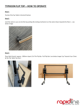
The Color Passive-Matrix touch panels contain an 8.5" (215.90 mm) 256-color passive-matrix
liquid crystal display (LCD). The self-contained enclosures use a microprocessor to control a wide
range of multimedia equipment. Using the TPDesign3 Touch Panel design program, you create
custom pages with buttons, icons, sliders, bargraphs, time displays, logos, and drawings.
8.5" Color Passive-Matrix touch panels include:
! AXD-CP (Decor-style) and AXD-CP/PB (Decor-style pushbutton)
! AXT-CP (TiltScreen) and AXT-CP/PB (TiltScreen pushbutton)
! AXM-CP (Rack-mount) and AXM-CP/PB (Rack-mount pushbutton)
Specifications
The table below lists the specifications for the AXD-CP (/PB), AXT-CP, and AXM-CP (/PB).
Specifications
Dimensions (HWD):
AXD-CP • 7.50" x 11.25" x 1.77" [low-profile Back Box] (17.48 cm x 28.58 cm x 4.5 cm)
• 7.50" x 11.25" x 2.44" [BB-TP2 Back Box] (17.48 cm x 28.58 cm x 6.2 cm)
AXT-CP • TiltScreen panel dimensions (HW): 7.10" x 9.11" (18.03 cm x 23.14 cm)
• LCD screen dimensions (HW): 4.80" x 6.40" (12.19 cm x 16.26 cm)
• Base dimensions (WD): 11.46" x 9.46" (29.11 cm x 24.03 cm)
• Adjustable display heights: 3.40" (8.64 cm) fully lowered; 8.50" (21.59 cm) fully
raised.
• Screen Dimensions (HW): 8.5" diagonal view - 4.80" x 6.40" (12.19 cm x 16.26
cm)
AXM-CP • 6.97" x 19.0" x 1.62" (low-profile Back Box) (17.70 cm x 48.26 cm x 4.11 cm)
• 6.97" x 19.0" x 2.64" (BB-TP2 Back Box) (17.70 cm x 48.26 cm x 6.71 cm)
Weight:
AXD-CP 4.5 lbs. (2.1 kg)
AXT-CP 3.6 lbs. (1.6 kg)
AXM-CP 4.4 lbs. (2.0 kg)
Power 650 mA @ 12 VDC
Display Type Color passive-matrix 256 color LCD
Screen Res. (HV) 640 x 480 pixels
Memory 1 MB
Rear Panel Connectors:
RS-232
AXlink
PWR
• DB-9 (male) connector for PC data transmission or Microsoft mouse control
• 4-pin male bus connector
• 2-pin male 12 VDC power connector

Product Information
2
Color Passive-Matrix LCD Touch Panels
Cleaning the Touch Overlay
You should clean the touch screen overlay after each day’s use. Always use clean cotton cloths, and
a spray bottle of cleaning solution consisting of 50% isopropyl alcohol and 50% water.
Specifications (Cont.)
Enclosure:
AXD-CP Metal sub-plate and bezel with black or white matte finish
AXT-CP TiltScreen tabletop console; black plastic with matte finish
AXM-CP 19" (48.3 cm) Unimount; metal with black matte finish (4 rack units high)
Accessories Included • 12 VDC power supply, 1.9 A (110 VAC installations only)
• Low-profile Back Box (AXD-CP and AXM-CP only)
• 4-pin female AXlink bus connector (AXM-CP only)
• 4-pin AXlink data/power connector (AXT-CP only)
Optional Accessories • Up to 8 pushbuttons per side for the AXD-CP and AXM-CP.
• 9-pin female DB-9 connector (AXD-CP and AXT-CP only.
• PSN2.8 Power Supply
• BB-TP2 Back Box (AXD-CP)
Software • TPDesign - Windows-based (16-bit) design program (optional for the AXT-CP)
• TPDesign3 - Windows-based (32-bit) design program (optional for the AXT-CP)
AXT-CP Wireless
Options:
TiltScreen • WAV-PK WavePack
• SMT-PK SmartPack
Options:
Decor-style Panels • External pushbuttons (AXD-CP (/PB))
• UniMount Back Box (BB-TP2) and sub-plate, bezel security plates

Installation
3
Color Passive-Matrix LCD Touch Panels
Installation
Mounting the Touch Panel
The following paragraphs describe mounting the Decor and rack-mount touch panels. TiltScreen
touch panels can be placed on any flat surface.
Decor style panels with low-profile Back Boxes
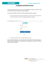
1. Cut out the surface using the dimensions shown in FIG. 1.
2. Carefully insert a flat-blade screwdriver into the release slot on the touch panel's faceplate and
remove the engraved overlay.
3. Place the touch panel into the cutout and mark the screw insert positions as shown in FIG. 1.
4. Remove the touch panel and drill four #6-32 insert holes. Then, place a threaded insert into
each hole.
5. Disconnect the AXlink connector from the Central Controller. Then, disconnect the optional
RS-232 wiring from the external RS-232 device connected to the touch panel.
FIG. 1 Decor style and low-profile Back Box output dimensions

Installation
4
Color Passive-Matrix LCD Touch Panels
6. Fasten the low-profile Back Box to the surface using the #6-32 machine screws supplied with
the enclosure.
7. Attach the data and power wiring to the touch panel.
8. Test the connection by reconnecting the AXlink connector to the Central Controller and
optional RS-232 wiring to the source equipment. Before continuing, disconnect all connections
until panel installation is complete. Once attached to the Decor style faceplate, the security
screws can’t be replaced without removing the overlay.
9. Fasten the touch panel and low-profile Back Box using the #6-32 machine screws supplied
with the enclosure panel.
10. Place the faceplate onto the bezel. You can also secure the faceplate to the bezel using the four
Phillips flat-head security screws.
11. Insert the engraved overlay back into the bezel.
12. Remove the backing from the adhesive tape strips located on the front of the touch panel; press
the engraved overlay onto the faceplate.
13. Reconnect the AXlink wiring to the Central Controller and RS-232 wiring (optional) to the
external RS-232 device. The touch panel beeps when you apply power.
Installing touch panels and a BB-TP2 Back Box (solid surface)
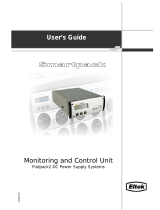
FIG. 2 shows a sample AXD-CP/PB and BB-TP2 Back Box for solid surfaces.
The BB-TP2 can also be mounted to wood or metal studs using the pre-drilled stud mounting holes.
1. Cut out the surface using the dimensions shown in FIG. 3.
FIG. 2 AXD-CP/PB and BB-TP2 Back Box (solid surfaces)
BB-TP2 Unimount
Backbox enclosure
Knockout
Solid surface mounting flanges
Stud mounting
holes
Engraved overlay
AXD-CP/PB
faceplate

Installation
5
Color Passive-Matrix LCD Touch Panels
2. Carefully insert a flat-blade screwdriver into the release slot on the touch panel’s bezel and
remove the engraved overlay.
3. Lay the touch panel facedown onto a soft cloth and remove the four screws from the low-
profile Back Box. Remove the Back Box and discard.
4. Place the BB-TP2 into the cutout and mark the threaded insert positions as shown in FIG. 3.
5. Remove the BB-TP2 and drill holes (A and B) for the panel (FIG. 3). Then, place #6-32
threaded inserts into the four holes marked 'B' in the cutout dimensions illustration.
6. Disconnect the AXlink connector from the Central Controller. Then, disconnect the optional
RS-232 wiring from the external RS-232 device connected to the touch panel.
7. Remove one or more knockouts to accommodate the wiring as required.
8. Thread the incoming AXlink and RS-232 wiring through the knockouts. Refer to theWiring the
Touch Panel section on page 8 for additional wiring information.
9. Fasten the BB-TP2 to the solid surface using the supplied mounting screws.
10. Connect the AXlink and RS-232 wiring to the touch panel.
FIG. 3 Decor style (AXD) and BB-TP2 cutout dimensions
The touch panel must always be installed with the release slot located at the bottom.

Installation
6
Color Passive-Matrix LCD Touch Panels
11. Test the connection by reconnecting the AXlink connector to the Central Controller and the
optional RS-232 wiring to the source equipment. The panel beeps upon power-up. Before
continuing, disconnect all connections until panel installation is complete.
12. Fasten the touch panel to the BB-TP2 using the #6-32 screws supplied with the panel.
13. Place the Decor-style faceplate onto the bezel. You can also secure the faceplate to the bezel
using the four Phillips flat-head security screws.
14. Remove the backing from the adhesive tape strips on the touch panel; press the engraved
overlay onto the faceplate. Once attached to the faceplate, the security screws cannot be
replaced without removing the battery.
15. Reconnect the AXlink wiring to the Central Controller and RS-232 wiring (optional) to the
external RS-232 device. The touch panel will beep when you apply power.
Installing touch panels and a BB-TP2 Back Box (plasterboard)
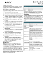
FIG. 4 shows the AXD-CP/PB and BB-TP2 Back Box for plasterboard.
1. Cut out the surface using the dimensions shown in FIG. 5.
2. Carefully insert a flat-blade screwdriver into the release slot on the touch panel's faceplate and
remove the engraved overlay.
3. Lay the touch panel facedown onto a soft cloth and remove the screws from the low-profile
Back Box. Remove the Back Box and discard.
4. Place the BB-TP2 into the cutout and mark the threaded insert positions (FIG. 4).
5. Remove the BB-TP2 and drill four #6-32 insert holes. Then, place a threaded insert (or screw
anchor) into each hole.
6. Disconnect the AXlink connector from the Central Controller that supplies power and data to
the touch panel. Then, disconnect the optional RS-232 wiring from the external RS-232 device
connected to the touch panel.
7. Remove one or more knockouts to accommodate the wiring as required.
FIG. 4 AXD-CP/PB and BB-TP2 Back Box (plasterboard)
BB-TP2 Unimount
Backbox enclosure
Knockout
Plasterboard surface mounting flange
s
Engraved overlay
AXD-CP/P
B
faceplate
Expansion clips

Installation
7
Color Passive-Matrix LCD Touch Panels
8. Thread the incoming AXlink and RS-232 wiring through the BB-TP2 knockouts. Refer
toWiring the Touch Panel section on page 8 for more information.
9. Fasten the BB-TP2 to the plasterboard using the expansion screws supplied with the enclosure.
10. Connect the AXlink and RS-232 wiring to the touch panel.
11. Test the connection by reconnecting the AXlink connector to the Central Controller and the
optional RS-232 wiring to the source equipment. The panel beeps on power-up. Before
continuing, disconnect all connections until panel installation is complete.
12. Fasten the touch panel to the BB-TP2 with the #6-32 screws supplied with the en-closure.
13. Place the Decor-style faceplate onto the bezel. You can also secure the faceplate to the bezel
using the four Phillips flat-head security screws.
14. Remove the backing from the adhesive tape strips. Once attached to the faceplate, the security
screws cannot be replaced without removing the overlay.
15. Press the engraved overlay onto the faceplate.
16. Reconnect the AXlink wiring to the Central Controller and RS-232 wiring (optional) to the
external RS-232 device. The touch panel beeps on power-up.
FIG. 5 Decor style (AXD) and BB-TP2 cutout dimensions for plasterboard

Installation
8
Color Passive-Matrix LCD Touch Panels
Rack-mount panel (AXM-CP/PB)
1. Thread the incoming AXlink and optional RS-232 wiring through the opening in the
equipment rack.
2. Disconnect the AXlink connector from the Central Controller and disconnect the optional RS-
232 connector from the external RS-232 device connected to the touch panel.
3. Insert the touch panel into the equipment rack. Line up the top-left and bottom-right screw
holes and start tightening the #6-32 screws. Then, tighten the bottom-left and top-right screws.
4. Connect the AXlink and RS-232 wiring (optional) to the touch panel. Refer to (DB-9) RS-232
Connector Pinouts table on page 10 for pinout descriptions. The touch panel beeps on
power-up.
Wiring the Touch Panel
The RS-232, AXlink, and PWR (power supply) connectors are located at the rear of the AXT-CP as
shown FIG. 6. The connectors are located on the top-left corner of the rack-mount touch panels as
shown in FIG. 7.
Preparing captive wires
You will need a wire stripper, soldering iron, and flat-blade screwdriver to prepare and connect the
captive wires.
1. Strip 0.25 inch of wire insulation off all wires and apply a light coat of solder to the ends using
a soldering iron.
2. Insert each wire into the appropriate opening on the connector according to the wiring
diagrams and connector types described in this subsection.
3. Turn the flat-blade screws clockwise to secure the wire in the connector. Do not over-torque
the screws; doing so can bend the seating pin and damage the connector.
FIG. 6 AXT-CP (rear view)
FIG. 7 AXD-CP (/PB) and AXM-CP (/PB) (top view)
DB-9 connector
Four-pin AXlink connector
Two-pin power connector
Four-pin AXlink connector
Two-pin power
connector
Do not connect power to the touch panel until the wiring is complete. If you are using
a 12 VDC power supply, apply power to the touch panel only after installation is
complete.

Installation
9
Color Passive-Matrix LCD Touch Panels
Wiring guidelines
The touch panels require 12 VDC power to operate properly. The Central Controller supplies power
via the AXlink cable or external 12 VDC power supply. The maximum wiring distance between the
Central Controller and touch panel is determined by power consumption, supplied voltage, and the
wire gauge used for the cable. The table below lists wire sizes and the maximum lengths allowable
between the touch panel and Central Controller. The maximum wiring lengths for using AXlink
power are based on a minimum of 13.5 volts available at the Central Controller's power supply.
Refer to theSpecifications section on page 1 for more information on power requirements.
If you install the touch panel farther away from the control system than recommended in the Wiring
Guidelines table, connect an external 12 VDC power supply to the 2-pin PWR connector on the
touch panel.
Using AXlink for data and power
Connect the Central Controller's AXlink connector to the AXlink connector on the touch panel for
data and 12 VDC power as shown in FIG. 8.
Using the AXlink for data with a 12 VDC power supply
Connect the Central Controller's AXlink connector to the AXlink connector on the touch panel and
external 12 VDC power supply as shown in FIG. 9.
Use an auxiliary 12 VDC power supply when the distance between the Central Controller and touch
panel exceeds the limits described in Wiring Guidelines table on page 9.
Connect only the GND wire on the AXlink connector when using a 12 VDC power supply. Do not
connect the PWR wire to the AXlink connector's PWR (+) terminal.
Wiring Guidelines
Wire Size Maximum Wiring Length
18 AWG 180.57 feet (55.04 m)
20 AWG 114.24 feet (34.82 m)
22 AWG 71.23 feet (21.71 m)
24 AWG 44.90 feet (13.69 m)
FIG. 8 AXlink wiring diagram
PWR (+)
AXP
AXM
GND (-)
PWR (+)
AXP
AXM
GND (-)
AXlink connector on the touch panel
Central Controller
If you are using power from AXlink, disconnect the wiring from the Central Controller
before wiring the touch panel.

Installation
10
Color Passive-Matrix LCD Touch Panels
Using the (DB-9) RS-232 connector for mouse control or data
The dual-function (DB-9) RS-232 connector supports most standard serial mouse control devices
and RS-232 communication protocols for PC data transmission. Refer to the TPDesign or
TPDesign3 Touch Panel Program instruction manual for data transmission information.
The table below lists (DB-9) RS-232 connector pinouts and FIG. 10 shows the (DB-9) RS-232
connector and power supply wiring diagram.
Use connector pins 2, 3, and 5 for data and ground. For some applications, you may need to strap
pins 7 (request to send) and 8 (clear to send) together depending on the PC.
FIG. 9 AXlink and external 12 VDC power supply wiring diagram
(DB-9) RS-232 Connector Pinouts
Pin Signal Function
1 N/A Not used
2 RXD Receive data
3 TXD Transmit data
4 DTR Data terminal ready (not used)
5 GND Signal ground
6 DSR Data set ready (not used)
7 RTS Request to send (not used)
8 CTS Clear to send (not used)
9 N/A Not used
FIG. 10 DB-9 RS-232 connector and power supply wiring diagram
PWR (+)
AXP
AXM
GND (-)
PWR (+)
AXP
AXM
GND (-)
AXlink connector on the touch panel
Central Controller
PWR (+)
GND (-)
12 VDC power supply
9
8
7
6
5
4
3
2
1
9
8
7
6
Female
Male
DB-9 (male)
DB-9 (female)
Power connector
Mouse or PC, DB-9 connector
Female
Male
Touch panel
DB-9 connector
Optional 7 to 8-pin
connector
2 (RXD)
3 (TXD)
5 (GND)
2 (RXD)
3 (TXD)
5 (GND)
+ (PWR)
- (GND)
12 VDC power supply

Designing Touch Panel Pages
11
Color Passive-Matrix LCD Touch Panels
Designing Touch Panel Pages
There are two ways to approach creating touch panel pages:
! TPDesign3 - Refer to the TPDesign3 Touch Panel Program (Version 3. 16 or higher)
Instruction Manual for more information.
! On-board editor
This document describes basic use of the on-board editor to create pages and buttons. Refer to the
G3 Firmware Design and Reference instruction manual for more detailed firmware information.
Buttons
Standard button types include rectangles and other geometric shapes you can create with the touch
panel editor. Buttons are set with attributes, meaning there is a response from the Central Controller
when you touch the button.
General buttons are part of the default touch panel program and cannot be changed. You use general
buttons to create or revise pages and specify panel communication parameters. Button examples
include selection buttons, information buttons, adjustment buttons, and operation bars. The general
button categories are described in the table below.
General Button Categories
Selection buttons Selection buttons appear on touch panel pages and set communica-
tion parameters.
Information buttons Information buttons contain serial numbers and firmware version
information. The properties of these buttons cannot be changed.
These buttons have a black fill and yellow text.
Adjustment buttons You can use the UP and DN buttons to set adjustment buttons. The
adjustment button example sets the baud rate for the connection
from the touch panel to the computer.
Keypad buttons The keypad button opens a keypad so you can enter a password or
value assignment. All keypad buttons are interactive except for the
entry display.
Decision buttons Decision buttons appear when an operation has two options and
requires verification before an action is performed.

Designing Touch Panel Pages
12
Color Passive-Matrix LCD Touch Panels
Activating Edit Mode
Before designing touch panel pages and buttons, you must activate EDIT mode. Once activated, use
the EDIT button to enter Edit mode. This mode has options to add and configure touch panels and
buttons. When powering up the touch panel, the first page is the Main page (see FIG. 11). Note that
the Edit button is not available initially.
General Button Categories (Cont.)
Status buttons Status buttons always have a black fill with white letters and have no
functionality except to display information.
Operation bars Operation bars appear in the place of the Editor bar, after selecting a
button or page edit operation. The operation bar indicates which edit
function is currently active. When an edit operation is selected, it
remains active until you press EXIT.
Touch to Continue buttons "Touch to Continue" buttons appear when an operation requires user
acknowledgement.
Joystick buttons Joysticks are vertical and horizontal direction controllers for use with
pan and tilt camera controllers.
Bargraph buttons Bargraph buttons display a dynamic bargraph (vertical or horizontal).
An example is the Batter level indicator button.
FIG. 11 Main Page
If you have a pre-programmed panel, you may not see the Main Page.

Designing Touch Panel Pages
13
Color Passive-Matrix LCD Touch Panels
To activate edit mode:
1. Press SETUP in the Main page to open the Setup page (FIG. 12).
2. Press PROTECTED SETUP to open the keypad.
3. Enter 1988 (default password) in the keypad and press ENTER to open Protected Setup page.
If you press ENTER after typing an incorrect password, you are immediately returned to the
previous page.
4. Press EDITOR to enable Edit mode. The EDITOR button is highlighted in the Protected Setup
page when enabled, as shown in FIG. 13.
5. Press EXIT to close the Protected Setup page and return to the Setup page (now in the Edit
mode).
6. Press EXIT again to return to the Main page. The EDIT button appears at the top of the page
indicating that Edit mode is active.
7. Press EDIT to open the Edit bar. The BUTTON and PAGE options, in the Edit bar, (FIG. 14)
are used to design and modify button and page settings.
FIG. 12 Setup page
FIG. 13 Protected Setup page with the active EDITOR button

Designing Touch Panel Pages
14
Color Passive-Matrix LCD Touch Panels
Setting the Device Base
Press the DEVICE BASE option, in the Protected Setup page (FIG. 13), to assign a base (starting)
device address to the touch panel.
1. Enter the base address for the touch panel. The base address range is from 1 - 255. Standard
device addresses begin at 128.
2. Press Enter to save.
Setting the Device Used
Use the DEVICE USED option in the Protected Setup page (FIG. 13) to assign a value for the
number of devices being controlled by the touch panel.
1. Press DEVICE USED to open the keypad and enter the panel’s device number from 1 - 4. Each
device number supports up to 255 programmable channel codes. The multiple device settings
allow you to create up to four unique touch panel buttons and/or pages. This value is used to
determine the current device being used by the panel.
2. Enter the number of devices being used by the touch panel.
3. Press Enter to save the value.
Adding a Page
1. Press PAGE on the Edit bar to open the PAGE menu.
2. Press ADD to open the keyboard and enter a name for the new page. Page names can be up to
20 characters.
3. Press EXIT CHANGE to save, close the keyboard, and go to the new page.
Setting the page color
1. Press EDIT to open the Edit bar on the newly created page.
2. Press PAGE on the Edit bar to open the PAGE menu.
3. Press PAGE COLOR to open the black and white color palette.
4. Select a color from the palette; the page automatically changes to the new color.
FIG. 14 Main page with Edit bar
Edi
t
b
ar

Designing Touch Panel Pages
15
Color Passive-Matrix LCD Touch Panels
Adding a Button
To add a button to the current page:
1. Press BUTTON on the Edit bar to open the BUTTON menu.
2. Press ADD to open the ADD BUTTON operation bar. On the LCD screen, touch and drag to
create a button. The first touch point is the upper-left corner of the button.
Resizing a button
1. Press BUTTON on the Edit bar to open the BUTTON menu.
2. Press RESIZE. Then, touch any edge of the button and drag. Removing your finger from the
panel saves the button dimensions.
Defining On-Screen and External Button Properties
External pushbuttons are configured with features similar to on-screen buttons. Their functionality
can be set just as any other button on the touch panel.
Use the PROPERTIES option of the BUTTON menu in the Edit bar to set button borders, page
flips, button colors for channel on/off conditions, channel/variable text codes, and string/macro
assignments.
External button properties include only the button type, page flips, channel codes, and string/macro
assignments. Although the Border and Color sections of this page appear, they are of no use to
external pushbuttons since they do not appear on-screen.
Use the following steps to set button properties:
1. Press BUTTON on the Edit bar to open the BUTTON menu options.
2. Press PROPERTIES to open the PROPERTIES operation bar.
3. Press the new button to open the Button Properties page. This page lists the properties for the
active button.
4. Press BUTTON TYPE; this opens the BUTTON TYPE menu.
5. Choose a button type for the selected button to open the associated Button Properties page.
Each button type has its own Button Properties page with settings specific to the button type.
6. Press BORDER to open the BUTTON BORDER pages.
7. Select a border to set for the button and return to the Button Properties page. The BORDER
button changes to show the selected border type.
Setting the channel code
The channel button sets the device and button channel codes.
1. In the Button Properties page, press DEV to open the keypad and set the touch panel’s device
number.
Channel codes and variable text codes work the same for all button types, including
joysticks, and bargraphs.

Designing Touch Panel Pages
16
Color Passive-Matrix LCD Touch Panels
2. Enter 1, 2, 3, or 4 in the keypad. The programming software uses device codes 1 - 4 to identify
the touch panel. Refer to the G3 Firmware Design and Reference instruction manual for more
information.
3. Press ENTER to save the device number, close the keypad, and return to the Button Properties
page.
4. Press CHAN to open the keypad and enter a channel value of 1 - 255. The source code uses the
channel code number to identify the button and its programmed operations. The channel code
for non-active buttons is 0.
5. Press ENTER to save the channel number, close the keypad, and return to the Button Properties
page.
Setting the variable text code
The variable text buttons set the device and button channel codes for the buttons.
1. Press DEV to open the keypad and set the device number.
2. Enter 1, 2, 3, or 4 in the keypad. The source code uses device codes 1 - 4 to identify the touch
panel.
3. Press ENTER to save, close the keypad, and return to the Button Properties page.
4. Press CHAN to open a keypad and set the channel number.
5. Enter a channel value of 1 - 255 in the keypad. The source code uses the channel code number
to identify the button and its operations.
6. Press ENTER to save the channel number, close the keypad, and return to the Button Properties
page.
Setting the page flip
1. Press the PAGE FLIP Type button (FIG. 15) in the Button Properties page to open the Page
Flip Type menu.
2. Select a Page Flip type. If you select FLIP PREVIOUS in the Page FLIP Type menu, the FLIP
to Page button appears.
3. Press the FLIP to Page button (FIG. 15) to open a list of all the saved touch panel pages. If the
desired page is not present in the menu, check to verify the page has been saved.
4. Select the target page for the page flip.
If DEVICE USED is set to 4 and Base Device Number is 128, the Controller recognizes
bus devices 128 - 131.
The panel will not allow you to enter a device number greater than the DEVICE USED
without first displaying a decision box asking if you accept the new selection or not.
FIG. 15 Page FLIP Type button
Flip to Page button
Page FLIP type
button
/