Page is loading ...

255373
Rev. C1 0223
Printed in U.S.A.
© Copyright 2008-2023 Federal Signal Corporation
SE2000+ Series C
Serial to Ethernet Converter with VoIP
Description, Specications,
and Setup Manual

Limited Warranty
This product is subject to and covered by a limited warranty,
a copy of which can be found at www.fedsig.com/SSG-Warranty.
A copy of this limited warranty can also be obtained by written
request to Federal Signal Corporation, 2645 Federal Signal Drive,
University Park, IL 60484, email to [email protected] or
call +1 708-534-3400.
This limited warranty is in lieu of all other warranties, express or
implied, contractual or statutory, including, but not limited to the
warranty of merchantability, warranty of tness for a particular
purpose and any warranty against failure of its essential purpose.
2645 Federal Signal Drive
University Park, Illinois 60484
www.fedsig.com
Customer Support 800-548-7229 • +1 708 534-3400
Technical Support 800-524-3021 • +1 708 534-3400
All product names or trademarks are properties of their respective owners.

3
Description, Specications, and Setup Manual
Federal Signal www.fedsig.com
Contents
Safety Messages......................................................................................................................................................4
General Description ................................................................................................................................................7
Introduction .........................................................................................................................................................7
Features .............................................................................................................................................................. 7
Specications ..........................................................................................................................................................8
Testing and Alignment .......................................................................................................................................... 11
Apply Power and Check Voltages ..................................................................................................................... 11
Testing Serial Port Com #1 and Programming the Unit .................................................................................... 11
Conrm Micro-Controller ................................................................................................................................... 11
600-Ohm Audio Output (JP2) ............................................................................................................................ 11
Input and Output Connections ..........................................................................................................................12
Conguring the SE2000+ Series C Using the Web Interface ............................................................................13
Logging on to the Web Browser ........................................................................................................................13
Changing the Network Settings ........................................................................................................................15
Conguring the RTU Settings ...........................................................................................................................16
Conguring the User Setup ...............................................................................................................................18
Uploading Firmware .......................................................................................................................................... 21
Rebooting Device and Loading Conguration Settings ....................................................................................22
Restoring Conguration to Factory Defaults .....................................................................................................22
Logging Out of the Web Interface .....................................................................................................................24
Getting Service ......................................................................................................................................................24
Tables
Table 1 Specications .............................................................................................................................................8
Table 2 Connectors .................................................................................................................................................8
Table 3 Relay Output ...............................................................................................................................................9
Table 4 Indicators ..................................................................................................................................................10
Table 5 Controls .....................................................................................................................................................10
Table 6 Network Information ................................................................................................................................10

4
Safety Messages
SE2000+ Series C
Federal Signal www.fedsig.com
Safety Messages
It is important to follow all instructions shipped with this product. This device is to be
installed by trained personnel who are thoroughly familiar with the country’s electric
codes and will follow these guidelines as well as local codes and ordinances, including
any state or local noise-control ordinances. Listed below are important safety instructions
and precautions you should follow.
Important Notice
Federal Signal reserves the right to make changes to devices and specifications detailed
in the manual at any time to improve reliability, function, or design. The information in
this manual has been carefully checked and is believed to be accurate; however, no
responsibility is assumed for any inaccuracies.
Publications
Federal Signal recommends the following publications from the Federal Emergency
Management Agency for assistance with planning an outdoor warning system:
• The “Outdoor Warning Guide” (CPG 1-17)
• “Civil Preparedness, Principles of Warning” (CPG 1-14)
• FEMA-REP-1, Appendix 3 (Nuclear Plant Guideline)
• FEMA-REP-10 (Nuclear Plant Guideline).
Planning
• If suitable warning equipment is not selected, the installation site for the siren is
not selected properly, or the siren is not installed properly, it may not produce the
intended optimum audible warning. Follow Federal Emergency Management Agency
(FEMA) recommendations.
• If sirens are not activated in a timely manner when an emergency condition
exists, they cannot provide the intended audible warning. It is imperative that
knowledgeable people, who are provided with the necessary information, be
available at all times to authorize the activation of the sirens.
• When sirens are used out of doors, people indoors may not be able to hear the
warning signals. Separate warning devices or procedures may be needed to warn
people indoors eectively.
• The sound output of sirens is capable of causing permanent hearing damage. To
prevent excessive exposure, carefully plan siren placement, post warnings, and
restrict access to areas near sirens. Review and comply with any local or state noise
control ordinances as well as OSHA noise exposure regulations and guidelines.
• Activating the sirens may not result in people taking the desired actions if those to
be warned are not properly trained about the meaning of siren sounds. Siren users
should follow FEMA recommendations and instruct those to be warned of corrective
actions to be taken.
• After installation, service, or maintenance, test the siren system to confirm that it is
operating properly. Test the system regularly to confirm that it will be operational in
an emergency.

5
Safety Messages
Description, Specications, and Setup Manual
Federal Signal www.fedsig.com
• If future service and operating personnel do not have these instructions to refer
to, the siren system may not provide the intended audible warning, and service
personnel may be exposed to death, permanent hearing loss, or other bodily injury.
File these instructions in a safe place and refer to them periodically. Give a copy of
these instructions to recruits and trainees. Also give a copy to anyone who is going to
service or repair the siren.
Installation and Service
• Electrocution or severe personal injury can occur when performing various
installation and service functions such as making electrical connections, drilling holes,
or lifting equipment. Therefore, only experienced and qualified electricians should
install this product in compliance with national, state, and any other applicable codes,
ordinances, and regulations. Perform all work under the direction of the installation or
service crew safety foreman.
• The sound output of sirens is capable of causing permanent hearing damage. To
prevent excessive exposure, carefully plan siren placement, post warnings, and
restrict access to areas near the sirens. Sirens may be operated from remote control
points. Whenever possible, disconnect all siren power, including batteries, before
working near the siren.
• After installation or service, test the siren system to confirm that it is operating
properly. Test the system regularly to confirm that it will be operational in an
emergency.
• If future service personnel do not have these warnings and all other instructions
shipped with the equipment to refer to, the siren system may not provide the
intended audible warning, and service personnel may be exposed to death,
permanent hearing loss, or other bodily injuries. File these instructions in a safe
place and refer to them periodically. Give a copy of these instructions to recruits and
trainees. Also give a copy to anyone who is going to service or repair the sirens.
Operation
Failure to understand the capabilities and limitations of your siren system could result
in permanent hearing loss, other serious injuries, or death to persons too close to
the sirens when you activate them or to those you need to warn. Carefully read and
thoroughly understand all safety notices in this manual and all operations-related items in
all instruction manuals shipped with the equipment. Thoroughly discuss all contingency
plans with those responsible for warning people in your community, company, or
jurisdiction.
Ethernet Wiring
• Unless shielded or run in conduit, Ethernet wiring must be at least six feet from bare
power wiring or lightning rods and associated wires, and at least six inches from
other wire (for example, antenna wires, doorbell wires, wires from transformers to
neon signs), steam or hot water pipes, and heating ducts.
• Do not place Ethernet wiring or connections in any conduit, outlet, or junction box
containing high voltage electrical wiring.
• If using a cable gland, the gland must be UL listed. The Speaker has 3/4-inch and
1/2-inch NPT entry sizes.

6
Safety Messages
SE2000+ Series C
Federal Signal www.fedsig.com
Symbol Definition
_A _V Indicates to reduce the risk of fire, replace the fuse as marked.
Pay careful attention to the notice located on the equipment.
Hazard Classification
Federal Signal uses signal words to identify the following:
DANGER indicates a hazardous situation which, if not avoided, will result in death or
serious injury.
WARNING indicates a hazardous situation which, if not avoided, could result in death or
serious injury.
CAUTION indicates a hazardous situation which, if not avoided, could result in minor or
moderate injury.
NOTICE is used to address practices not related to physical injury.
Read and understand the information contained in this manual before attempting
to install or service the siren.

7
General Description
Description, Specications, and Setup Manual
Federal Signal www.fedsig.com
General Description
Introduction
The SE2000+ Series C (Serial to Ethernet Converter) allows serial devices to
communicate over an Ethernet network and provide audio decoding of digitized audio
sent over the network.
The converter is configured with its own fixed IP address and port number. When data
packets are received over the Ethernet port addressed to the board’s IP and port
number, they are converted to serial data and sent out over the serial port. Likewise, any
data coming into the serial port is converted to TCP/IP data packets and sent out over
the Ethernet port to the Server’s IP address. The unit also contains a digital to analog
converter that allows specially configured incoming data packets to be converted to audio
and then filtered and sent out over a 600-ohm audio port.
The SE2000 can incorporate up to two serial to Ethernet conversions and includes an
auxiliary serial port and a MeterBus port for communicating with solar chargers. Ethernet
port one is the default port. Ethernet port two is inactive and for future use or use in
special requests.
The SE2000+ is designed to use the SmartMsg interoperable, redundant server platform.
Features
The SE2000+ has the following features:
• User-configurable IP addresses
• Digital to analog conversion allowing reception of Voice over Internet Protocol (VoIP)
• G.711 Audio Compression and Expansion for reduced noise in recovered audio
• Wide-input supply range allowing connection to a wide variety of power sources
• 600-ohm audio output for easy and universal audio interface
• Display LEDs to monitor Power, CPU, Network, Talking, TXD and RXD
• Integrated web server allows users to configure the SE2000+ from standard web
browsers
• Commander® and CommanderOne® HMI software provide configuration, control,
activation, and notification options
• Integral local RS232 port for local control, configuration, and programming
• Integral password protection and IP address firewall
• IP QOS prioritization using IP ToS Precedence (RFC791) or DSCP (RFC2474)

8
Specications
SE2000+ Series C
Federal Signal www.fedsig.com
Specications
Table 1 Specications
Electrical
Input Voltage 10-95 Vdc
Current Draw
1 Ethernet Port
2 Ethernet Ports
< 185 or 310 mA at 5 V
< 100 mA at 12 V, < 50 mA at 24 V, < 25 mA at 48 V
< 160 mA at 12 V, < 80 mA at 24 V,< 40 mA at 48 V
Serial Ports RS232C, N, 8, 1 baud rate congurable
MeterBus Port MorningStar® MeterBus serial protocol
Ethernet Ports IEEE 802.3, 10BASE-T connection
600 ohm Audio Output Port
Protection MOV and transorb surge protection
Audio Output Level Adjustable from 0.30 to 3.00 VP-P,
(-17 dB to +2.7 dB) into 600 ohms
Operating Temperature range -22°F to 149°F (-30°C to +65°C)
Humidity 0-95% non-condensing
Dimensions (H x W x L) 2 x 4 x 6.5 inches (5.08 x 10.16 x 16.51 cm)
Weight < 2 lb (0.9 kg)
Table 2 Connectors
JP1 JTAG Emulation Port
JP1 Relay Output
Normally open contacts, 2 A, 220 Vac, 30 Vdc
JP2 600-Ohm Audio Output Port
Balanced line output
JP3 Option #2 jumper
JP4 Option #1 jumper
JP5 Default jumper
Default settings in rmware
JP6 FLASH Programming Port
1 –
2 – TX Data, standard RS232 levels
3 – RX Data, standard RS232 levels
4 – Ground
5 – Serial Clock input for FLASH programming, standard RS232 levels
6 – Processor Reset Not line, used in programming FLASH, 10 K pull-up
JP7 Auxiliary RS232/Serial Port
1 – +12 V in
2 – Com #3 TX Data, standard RS232 levels
3 – Com #3 RX Data, standard RS232 levels
4 – Ground, 0.5 Amps max current capacity
5 – Com #2 TX Data, standard RS232 levels
6 – Com #2 RX Data, standard RS232 levels
7 – Ground, 0.5 Amps max current capacity
8 – +12 V in

9
Specications
Description, Specications, and Setup Manual
Federal Signal www.fedsig.com
JP8 RS232/Serial Port
1 – +12 V in
2 –
3 –
4 – Ground, 0.5 Amps max current capacity
5 – Com #1 TX Data, standard RS232 levels
6 – Com #1 RX Data, standard RS232 levels
7 – Ground, 0.5 Amps max current capacity
8 – +12 V in
JP9 Ethernet Port # 1 Default jumper
Default settings in rmware
Used for testing purposes
JP10 Ethernet Port # 2 Default jumper
Default settings in rmware
Used for testing purposes
JP11 MorningStar® MeterBus Port
Optically Isolated, Single wire
1 – (+) Power input
2 – (+) Power input
3 – GND
4 – TX Data / RX Data
5 – GND
6 – GND
JP12 Solar Regulator Serial Port
1 –
2 – Com #3 TXD into JP7
3 – Com #3 RXD out from JP7
4 – (+5 V) serial port phantom power
5 – GND
6 –
7 – (-5 V) serial port phantom power
8 –
9 –
JP13 10-95 Vdc Power Input
1 – (-)
JP14 Test Mode Jumper
M1 Ethernet Network Port #1
1 & 2 – Transmit data pair, balanced line
3 & 6 – Receive data pair, balanced line
4, 5, 7, 8 – AC coupled ground
M2 Ethernet Network Port #2
1 & 2 – Transmit data pair, balanced line
3 & 6 – Receive data pair, balanced line
4, 5, 7, 8 – AC coupled ground
Table 3 Relay Output
Normally Open Contacts, Rating 2 A, 220 Vac, 30 Vdc

10
Specications
SE2000+ Series C
Federal Signal www.fedsig.com
Table 4 Indicators
D1 Power indicator, green
D2 CPU Heartbeat indicator, green
D7 Receive data indicator, yellow
D8 Transmit data indicator, red
D9 Relay output indicator, red
D12 Ethernet port #1 Network connection indicator, green
D13 Ethernet port #1 Talk indicator, red
D15 Ethernet port #1 Network connection indicator, green
D16 Ethernet port #1 Talk indicator, red
Table 5 Controls
R1 600-ohm audio output level set
Table 6 Network Information
Protocols Supported TCP/IP (only supported with SmartMsg servers)
• HTTP
• UDP (for future use)
• XML (for future use)
• XMPP (for future use)
IP Ports Used 16887 (SmartMsg TCP/IP)
80 (HTTP)
3100 (UDP and TCP/IP Serial over IP – not currently using)
3101 (UDP and TCP/IP Voice over IP – not currently using)
IP Address User selectable
ToS/DSCP
(Type of Service)
ToS (RFC 791) values 0-7 are used
DSCP (RFC 2474) values 0-63 are used
Bandwidth
Requirements
Voice over IP: 150 K bps/connection
Siren Activation: 450 bps/connection
Siren Poll Response: 593 bps/connection

11
Testing and Alignment
Description, Specications, and Setup Manual
Federal Signal www.fedsig.com
Testing and Alignment
SYSTEM DAMAGE POSSIBLE: This device is to be serviced or maintained by
qualied personnel familiar with the controls and power sources used and in
conjunction with the authorities having jurisdiction.
Use this procedure to test the SE2000+ Serial to Ethernet converter to verify that it is
operating properly and set to the appropriate audio output level.
Apply Power and Check Voltages
To apply power and check the voltages:
1. Apply power to the Serial to Ethernet converter from 12 Volt bench supply.
2. Using TP2 as reference ground:
• Confirm 4.83 to 5.20 V on TP5.
• Confirm 3.19 to 3.41 V on TP6.
• Confirm 4.5 to 5.50 V on JP12 pin 4.
• Confirm -4.5 to -5.50 V on JP12 pin 7.
• Confirm that D1, the POWER LED, is on.
Testing Serial Port Com #1 and Programming the Unit
These steps are for authorized service personnel and require appropriate software and
cables to complete. Contact Technical Support. See “Getting Service” on page 24.
To flash firmware to the SE2000+ board:
1. Plug the FLASH serial cable into a computer and JP6 on the unit.
2. Start the Windows® based FLASHing program and then follow the instruction to
update the software of the unit.
This procedure confirms that the FLASH serial port is functioning.
Conrm Micro-Controller
Confirm that the CPU heartbeat LED (D2) is flashing.
600-Ohm Audio Output (JP2)
Power the unit o and then back on. On power-up, the unit will send from one serial port
to the other and then back again. If the data makes the full round trip, the serial ports are
working. If successful, the unit generates a 1 kHz tone out of the 600-ohm port.
Monitor the output of the 600-ohm port and adjust pot R1 until this level is 354 mVRMS,
+/-10%.

12
Testing and Alignment
SE2000+ Series C
Federal Signal www.fedsig.com
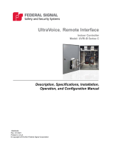
Input and Output Connections
The following figure identifies the input and output connections on the control board.
Figure 1 SE2000+ Control Board
D17
D20
R16
R15
C24
R34
D23
U12
D24
C38
C20
Q4 C43
C44 C47
C50
D28
R27
Q1
C22
U3
D11
R19
R18
C23
D3
R4
R2 C4
D15
D14
R21
R22
D16
C8
R5 C9
R6
R7
C12
C11
D21
R29
R30
R26
R8
R9
R36
JP14
TP3
C26
C56
D25
TP6
C32
JP3
R47
JP4
R53
JP5
C46C45
U18
C67
C59
D26
C68
C49
C53
D27
C52
C54
C21
R24
R23
U8 C27 C28
C57
U16 R41
R43
R50
R46
R48
C62
D19
D18
R11
R12 D9
TP1
TP4
TP2
C15
R54
C42
C58
R45 R49
R57
R52
R42
D29
C65 C66
C48
U22
C37
C34
R28
R13
D10
R17
D12
C16
D13
V1
R1
T1
C1
C18
C17
R20
U1
C5
C6
C7
C10
C3
R3
TP5
D22
U14 R39
R33
Q3
R35
R37
C29
R25
C13
C14
R10
D30
C60
U24
R55
R56
L2
C31
C39
U17
C30
D5D4 D6
C63
F1
JP13
C33
R32
U26
U19
C55
C41
U20
U9 Q2
C51
U10
R14
_
+
K1
JP9
F
M1
U7
JP10
R38
C25
C19
C36
R31
C61
C40
R51
R40
R44
U23
C64
U21
U25
D2
D1
C35
U15
JP11
JP7
D7
D8
U4
C2
J1
U2
JP2
JP1
U13
U5
U11
F
M2
JP12
JP8
JP6
U6
L1
Audio Output (JP2)
Relay Output (JP1)
FLASH Programming
Port (JP6)
Serial Port (JP8)
Auxiliary Serial
Port (JP7) Power Input (JP13)
Audio Output
Level Set (R1)
TXDRXDCPU
27
26
24
2 1
ISO
GND
ISO
99
+3.3V
50
52
7475
76
FLASH
LEVEL
OUTPUT
25
+5V
OPTION2
51
77
POWER
ETHERNET PORT 1
TALK
RELAY
OUTPUT
ETHERNET PORT 2
TALK
2005457F-__
+5V
100
TEST
49
(+)
DEFAULT
OUTPUT
AUDIO
DEFAULT
D/A
GND
OPTION1
DEFAULT
1 Amp
(-)
NETWRK
NETWRK
Solar Regulator
MeterBus
ISO PWR
Federal Signal Corporation Copyright 2020
SILKSCREEN
AUX SERIAL PORT
SERIAL PORT
BOTTOM / SOLDER SIDE SILKSCREEN

13
Conguring the SE2000+ Series C Using the Web Interface
Description, Specications, and Setup Manual
Federal Signal www.fedsig.com
Conguring the SE2000+ Series C Using the Web Interface
Ethernet port one is the default port. Ethernet port two is inactive and for future use or
use in special requests.
The following section describes how to activate from a built-in web server that allows the
SE2000+ to be controlled and configured over a LAN using standard web browsers.
The System Administrator identifies the server IP address, Subnet Mask, Default Gateway,
and the IP addresses for all SE2000+ devices.
If the configuration details are lost or changed incorrectly, and it becomes necessary to
restore the SE2000+ to factory default settings, see “Restoring Configuration to Factory
Defaults” on page 22.
Logging on to the Web Browser
To configure the network interface through the web browser:
1. Type the IP address into your Chrome®, Edge®, or Firefox® browser to navigate to the
SE2000+ web page.
The Login window appears.
2. Enter the Username:
admin (or pre-congured Username)
NOTE: If you change the Username or Password, record them.
3. Enter the Password:
fedsig (or pre-congured Password)
NOTE: The password is case sensitive.
4. Click Sign in.

14
Conguring the SE2000+ Series C Using the Web Interface
SE2000+ Series C
Federal Signal www.fedsig.com
The Home page appears.
The home page displays a summary of the current configuration settings for the RTU.
The Navigation Menu (blue hyperlinks on the left) is used to access other System
Management web pages.
Use the Help hyperlink to access the Help screen from any web page.
Field Description
Model The RTU model of the device. This eld will be blank for a
few minutes following power up or master reset.
RTU Number The RTU’s assigned identity.
Description The text eld is used to describe the RTU.
SmartMsg Server The RTU’s assigned default SmartMsg server.
SmartMsg Failover List The RTU’s SmartMsg Failover List. This eld will be blank
until the unit successfully connects to the server and
retrieves the failover list.
MAC Address The MAC Address of the device.
IPv4 Addresses The RTU’s assigned IPV4 address or its domain name.
DIGI Firmware Version The rmware version of the DIGI Connect ME 9210 module.
RTU Firmware Version The rmware version of the RTU.
Up Time The elapsed time since power up or reboot.
5. Record the MAC and IP address to ensure the device can be managed in the future.

15
Conguring the SE2000+ Series C Using the Web Interface
Description, Specications, and Setup Manual
Federal Signal www.fedsig.com
Changing the Network Settings
You can configure the RTU to obtain an IP address automatically using DHCP and AutoIP,
or you can assign a static IP address. Coordinate the static IP addresses with the system
Network Manager to prevent address duplication.
You cannot leave the Default Gateway blank when a static IP address is assigned. A valid
IP address is required. Use the server’s IP address as the gateway if making a direct
Ethernet connection to the device.
After changes are made, click the Apply button and reboot the RTU to begin using the
new configuration settings. Reboot the RTU by cycling power or from the Reboot web
page.
Use a MAC/IP address discovery tool to locate the IP address of the RTU if the network
configuration settings are lost, misconfigured, or if DHCP is used. You must use the
tool on the same side of a network router as the RTU. Contact Federal Signal Customer
Support for assistance with the discovery tool. See “Getting Service” on page 24.
To change the Network Settings of the SE2000+:
1. Select Network. The Network Settings page appears.
Fields Description
Obtain an
IP address
automatically
When the device is rebooted, it obtains new network settings
automatically from the network DHCP server.
Use the
following IP
address
Supplies static settings. You must enter an IP Address, Subnet Mask,
and Gateway. A DNS server address is only required if domain names
are used instead of IP addresses.
IP Address or
Domain Name
The RTU’s assigned IPV4 address or its domain name in the IP
address eld.

16
Conguring the SE2000+ Series C Using the Web Interface
SE2000+ Series C
Federal Signal www.fedsig.com
Fields Description
Subnet Mask The RTU’s assigned subnet mask.
Default
Gateway
The RTU’s network gateway for routing IP trafc.
Primary DNS The Primary Domain Name Server for the network. (Must be entered
if the RTU is required to connect to a server by its domain name.)
Secondary
DNS
The Secondary Domain Name Server for the network.
Apply Saves your settings. You must reboot for changes to take effect.
2. Select the Use the following IP address option button.
3. Enter the static IP Address, Subnet Mask, and Default Gateway for the device.
4. Click Apply.
5. Reboot the device for the IP address change to take eect.
NOTE: The factory default IP settings must be changed to work with the IP network that
the product will be connected to. Consult with your Network Manager to ensure the
settings adhere to your network policy.
Once the IP address is changed, configuration is only possible when the SE2000+ and
the configuration computer are placed on the live network together. Reconfigure the
configuration computer’s IP settings before returning to the live network. You now need to
log on to the web page with the new IP address after the address is changed.
NOTE: You can use DHCP to simplify SE2000+ deployment, but MAC address discovery
tools may not traverse routers, and maintenance may be more dicult.
Conguring the RTU Settings
Use the RTU Settings page to configure the device’s RTU Number and Description. All
devices in the system must have a unique RTU Number.
SmartMsg
Use the SmartMsg check box to enable or disable the SmartMsg network interface. To
use the interface, check the box and enter the IP address of the SmartMsg server. The
port is preconfigured to 16887. When applied, the RTU attempts to log on to the SmartMsg
server. If a server connection is lost for over 10 minutes, the unit performs a hardware and
software reset; therefore, to prevent interruption of other system services, disable the
interface if not in use.
After changes are made, click the Apply button, and then reboot the RTU from the Reboot
web page to begin using the new configuration settings.

17
Conguring the SE2000+ Series C Using the Web Interface
Description, Specications, and Setup Manual
Federal Signal www.fedsig.com
To change the configure the RTU Settings of the SE2000+:
1. Select RTU Settings.
The RTU Settings page appears.
Field Description
General
RTU Number The RTU’s assigned identity. All devices in the system must
have a unique RTU Number. The number must be a positive
integer.
Description This 48-character text eld is used to describe the RTU. This
can be the physical address of the site or any other text string.
The Description eld has a 255-character limit and can be
scrolled to view additional characters.
Serial Port Baud
Rate
Use to set the baud rate of Serial Port JP8.
Aux Serial Port Baud
Rate
Use to set the baud rate of Aux Serial Port JP7.
Underrun (Jitter)
Delay
Underrun occurs when a device runs out of data during live
streaming PA or VoIP, causing the audio to cut out, also
known as buffering. To mitigate buffering, the underrun delay
setting allows playback to be delayed by a xed duration to
allow the device to accumulate data before playback begins.
This headroom will help ll in the gaps in the event network
speed is insufcient for live voice. Set the number of seconds
the device will buffer the audio before starting playback.
On reliable high-speed networks, 1 or 2 seconds should be
sufcient. Slow networks and some wireless systems may
require 5 seconds or more to eliminate jitter.

18
Conguring the SE2000+ Series C Using the Web Interface
SE2000+ Series C
Federal Signal www.fedsig.com
Field Description
SmartMsg
Enable SmartMsg Check the Enable SmartMsg box to enable the SmartMsg
interface.
SmartMsg Server The RTU’s assigned default SmartMsg Server IP Address or
DNS name.
SmartMsg Port The port is precongured to 16887.
Apply Saves your settings. You must reboot for changes to take
effect.
2. Enter the RTU Number.
3. Enter a description of the RTU.
4. Select the Serial Port Baud Rate.
5. Select the Aux Serial Port Baud Rate.
6. Type the Underrun (Jitter) Delay.
7. Click Enable SmartMsg to enable the SmartMsg interface.
8. Click Apply.
9. Reboot the device for the IP address change to take eect.
Conguring the User Setup
User Setup allows Full Admin privileged users to create users, passwords, and assign
security privileges.
Enter up to five usernames. Each username requires a password and a security privilege.
Three privilege levels are available to restrict access to configuration screens:
• The View Only privilege enables the user to view the Home screen only.
• The View and Configuration privilege can configure all settings except User Setup.
• The Full Admin privilege has unrestricted access to all configuration screens.
The default Admin username is admin. The default password is fedsig. The Admin user
cannot be deleted, and its security privilege cannot be changed. The Admin user’s
username and password can be changed.
User 1 - User 4 are optional users that have configurable names, passwords, and
privileges.
Enable Factory Support User: When enabled, a hidden static user and password is
enabled for Federal Signal Technical Support. This user can be disabled.
After changes are made, click the Apply button. Reboot the RTU from the Reboot web
page to load the changes into the RTU.

19
Conguring the SE2000+ Series C Using the Web Interface
Description, Specications, and Setup Manual
Federal Signal www.fedsig.com
To create users and enable the factory support user:
1. Select User Setup.
The User Setup page appears.
Field Description
Username Enter the name of the user (case sensitive).
Password Enter the user’s password (case sensitive).
Password Conrm Enter the user’s password again. The Password Conrm must
match the Password.

20
Conguring the SE2000+ Series C Using the Web Interface
SE2000+ Series C
Federal Signal www.fedsig.com
Field Description
Privileges Three privilege levels are available to restrict access to
conguration screens:
• The View Only privilege enables the user to view the
Home screen only.
• The View and Conguration privilege can congure all
settings except User Setup.
• The Full Admin privilege has unrestricted access to all
conguration screens. The default Admin username is
admin. The default password is fedsig. The Admin user
cannot be deleted, and its security privilege cannot be
changed. The Admin user’s username and password can
be changed.
Enable Factory
Support User
Check the box to enable the factory support user.
Apply Saves your settings. You must reboot for changes to take
effect.
2. For the Admin fields, enter the default Username:
admin (This is the default username.)
3. For the Admin fields, enter the Password:
fedsig (This is the default password.)
NOTE: The password is case sensitive.
4. Enter the fields for User 1 through User 4 to create optional users. Each username
requires a password and a security privilege.
5. Click Enable Factory Support User to enable a hidden static user and password for
Federal Signal Technical Support.
6. Click Apply to save changes.
7. Reboot the device to load the changes into the RTU.
/