Marantec Comfort 211 Owner's manual
- Category
- Garage Door Opener
- Type
- Owner's manual
This manual is also suitable for
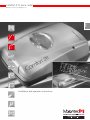
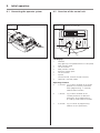
Marantec Comfort 211 EOS accu/solar is a versatile garage door operator system suitable for small and medium garage doors weighing up to 75 kg. It features automatic cut-out for open and close positions, obstacle detection for reversing the door, and adjustable speed and force settings. The Comfort 211 EOS accu/solar also includes a solar module for charging the battery, an accumulator unit for backup power, and a hand transmitter for remote control operation.
Marantec Comfort 211 EOS accu/solar is a versatile garage door operator system suitable for small and medium garage doors weighing up to 75 kg. It features automatic cut-out for open and close positions, obstacle detection for reversing the door, and adjustable speed and force settings. The Comfort 211 EOS accu/solar also includes a solar module for charging the battery, an accumulator unit for backup power, and a hand transmitter for remote control operation.


-
 1
1
-
 2
2
-
 3
3
-
 4
4
-
 5
5
-
 6
6
-
 7
7
-
 8
8
-
 9
9
-
 10
10
-
 11
11
-
 12
12
-
 13
13
-
 14
14
-
 15
15
-
 16
16
-
 17
17
-
 18
18
-
 19
19
-
 20
20
-
 21
21
-
 22
22
-
 23
23
-
 24
24
-
 25
25
-
 26
26
-
 27
27
-
 28
28
-
 29
29
-
 30
30
-
 31
31
-
 32
32
-
 33
33
-
 34
34
-
 35
35
-
 36
36


Marantec Comfort 211 Owner's manual
- Category
- Garage Door Opener
- Type
- Owner's manual
- This manual is also suitable for
Marantec Comfort 211 EOS accu/solar is a versatile garage door operator system suitable for small and medium garage doors weighing up to 75 kg. It features automatic cut-out for open and close positions, obstacle detection for reversing the door, and adjustable speed and force settings. The Comfort 211 EOS accu/solar also includes a solar module for charging the battery, an accumulator unit for backup power, and a hand transmitter for remote control operation.
Ask a question and I''ll find the answer in the document
Finding information in a document is now easier with AI
Related papers
-
Marantec Comfort 211 accu/solar Owner's manual
-
-
Marantec Comfort 250 Owner's manual
-
Marantec Comfort 220 Owner's manual
-
Marantec Comfort 211 EOS accu/solar Owner's manual
-
Marantec Digital 310 Owner's manual
-
-
-
Marantec Comfort 252 EOS Owner's manual
-
Other documents
-
 Sargent 2600 Series Instructions For Installation Manual
-
Chacon 56041 User manual
-
 Seip Solar FR I Installation guide
-
Chamberlain 3453135556 User manual
-
 Cardale DC 650 T Installation Instructions Manual
-
 Seip TS Series Installation guide
-
Hikvision DS-TMG4B1 User manual
-
Climax WTRQ2 User manual
-
Gardena Accu 3 Operating Instructions Manual
-
 ACCU-JOGGER ACCU-JOGGER Operating instructions


