Page is loading ...

Instructions For
Installation and Programming
2600 Series
Low-Energy Swing Door
Operator
Push and Pull Applications
A7311D

1
TABLE OF CONTENTS
DOOR OPERATOR COMPONENTS . . . . . . . . . .2
WARNINGS AND GUIDELINES . . . . . . . . . . . . . .3
FEATURES AND FUNCTIONS . . . . . . . . . . . . . . .4
INSTALLATION PROCEDURE . . . . . . . . . . . . . . 4
Tools Required . . . . . . . . . . . . . . . . . . . . . . . .4
Identify Door Application . . . . . . . . . . . . . . . .4
Push Application Installation . . . . . . . . . . . 5-7
Pull Application Installation . . . . . . . . . . .8-10
Initial Electrical Connections . . . . . . . . . . . .11
Power Requirements/Connections . . . . . . .11
External Fire Alarm Connection . . . . . . . . . .12
Battery Alarm Wiring . . . . . . . . . . . . . . . . . .13
DETAILED PROGRAMMING . . . . . . . . . . . . . . . .14
Initial Set Up and Programming . . . . . . . . . .14
Programming with the Control Unit . . . . . . .14
Display and Program Buttons . . . . . . . . .14-16
Restore Factory Settings . . . . . . . . . . . . . . .15
Test the Unit . . . . . . . . . . . . . . . . . . . . . . . . .16
Display LED’s . . . . . . . . . . . . . . . . . . . . . . . .17
Programming a Control Point . . . . . . . . .18-19
Sealed Control Points . . . . . . . . . . . . . . . . .20
Control Points . . . . . . . . . . . . . . . . . . . . 21-24
Control Points Affecting Speed
and Closing Force . . . . . . . . . . . . . . . . . . .25
Programming Suggestions . . . . . . . . . . . . . .25
BATTERY OPERATION . . . . . . . . . . . . . . . . . . . .26
Fire Door Use . . . . . . . . . . . . . . . . . . . . . . . .26
Battery Tests . . . . . . . . . . . . . . . . . . . . . . . .26
Power Failure In Fire Door Mode . . . . . . . . .27
Fire Adapter . . . . . . . . . . . . . . . . . . . . . . . . .27
FUNCTIONS . . . . . . . . . . . . . . . . . . . . . . . . . . . .27
ELECTRICAL WIRING . . . . . . . . . . . . . . . . . . . .27
Control Unit Input/Output Connections
and Functions . . . . . . . . . . . . . . . . . . . . . .27
Typical Applications . . . . . . . . . . . . . . . . 28-31
HAND HELD PROGRAMMER . . . . . . . . . . . . . . .32
RESTORING TO FACTORY SETTINGS WITH
THE HAND HELD PROGRAMMER . . . . . . . .33
TROUBLESHOOT COMMON PROBLEMS . . . . .34
Common Problems . . . . . . . . . . . . . . . . . . .34
Error (E) Codes . . . . . . . . . . . . . . . . . . . . . . .34

2
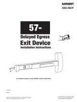
DOOR OPERATOR COMPONENTS
1
2
3
4
5
6
7
8
9
11
11
10
9
8
7
5
6
15
3
1
2
4
2651
2652
12
13
14
16
2660
ITEM PART NO. DESCRIPTION REQ.
1 63-3603 Main Switch 1
2 63-3600 Mode Selector Switch 1
3 63-0607 End Cover 1
4 63-3592 LED Electronics Assembly 1
5 63-3606 Control Unit Assembly 1
6 63-3604 Transformer Assembly 1
7 63-3599 Position Sensor 1
8 63-3605 Side Motor Mount 1
9 63-3602 Motor and Drive Gear Assembly 1
10 63-0606 End Cover 1
11 63-3601 Back Motor Mount 1
12 63-3593 Standard Arm—2651 1
13 63-3594 Extended Arm—2652 1
14 63-3595 Track Type Arm—2660 (Non-Handed) 1
15 63-0608 Mounting Plate 1
63-0603 Spindle Extension 3/8”
16 63-0604 Spindle Extensions 3/4” 1
63-0605 Spindle Extensions 2 3/8”
17 63-3596 Battery Pack (not shown) 1

3
WARNING
The SARGENT 2600 Series Low-Energy Door Operator is intended to be used in low-energy handicap
applications. Guidelines for low-energy can be found in ANSI Standard A156.19, American National Standard for
Power Assist and Low-Energy Power Operated Doors.
Generally speaking, low-energy doors move slowly, and therefore generate minimal levels of kinetic energy.
SARGENT recommends that the hold-open time for a low-energy door be not less than 10 seconds. Also, local fire
codes requirements for hold-open time should be taken into consideration.
Minimum opening and closing times for doors of various widths and weights are summarized in the table below.
Minimum Opening Time to Back Check or 80 deg or
Minimum Closing Time from 90 deg to Latch Check or 10 deg
Doors of other weights and widths can be calculated using the formula:
T= D W Where: T = Time in sec
133 lb-ft D = Door width in inches
W = Door weight in lb
CLOSING FORCE MUST NOT EXCEED 15 LB FOR A LOW-ENERGY APPLICATION. IF CLOSING FORCE
EXCEEDS 15 LB, THE DOOR WILL NOT MEET THE REQUIREMENTS OF ANSI STANDARD A156.19, AMERICAN
NATIONAL STANDARD FOR POWER ASSIST AND LOW ENERGY POWER OPERATED DOORS.
LATCHING SPEED MUST BE SUCH THAT THE DOOR TAKES AT LEAST 1.5 SEC TO MOVE FROM LATCHING
SPEED STARTING POINT TO FULLY CLOSED.
WHEN INSTALLATION IS COMPLETE, SET CONTROL POINT 15 TO 1, FIRE DOOR MODE. WHEN A FIRE ALARM
IS ACTIVATED, THE DOOR IS OPENED MANUALLY AND CLOSED UNDER POWER. IF THIS SETTING IS NOT 1,
THE DOOR WILL NOT ACHIEVE UL COMPLIANCE.
WARNINGS AND GUIDELINES
“D” Door
Width in “W” Door Weight in Pounds
Inches
100 125 150 175 200
30 3.0 sec 3.0 sec 3.0 sec 3.0 sec 3.5 sec
36 3.0 sec 3.5 sec 3.5 sec 4.0 sec 4.0 sec
42 3.5 sec 4.0 sec 4.0 sec 4.5 sec 4.5 sec
48 4.0 sec 4.5 sec 4.5 sec 5.0 sec 5.5 sec

4
• Programmable door weight up to 275 lbs. (125 Kg)
• All functions are programmable at the Operator or using an optional hand held programmer.
• Door can be activated by a delayed or non delayed impulse (See wiring)
• Battery backup for closing during fire or loss of power
• Adjustable hold open time 0-60 seconds
• Push and go manual opening (Intended to assist physically challenged only)
• Built in 12 or 24 VDC power supply for external locking devices(800mA max @ 24VDC)
• Lock control relay NO/NC operation
• Concealed wiring, standard
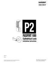
PUSH APPLICATION
PULL APPLICATION
PUSH APPLICATION
PULL
APPLICATION
Identify your type of application. This value will be necessary for programming. The 2600 Series Swing Door
Operator can be installed in any of four applications:
CONTROL
POINT
14 = 0
CONTROL
POINT
14 = 1
Identify Door Application
GO TO APPLICABLE INSTALLATION INSTRUCTIONS ...
FEATURES AND FUNCTIONS
NOTE: DOOR STOP IS REQUIRED TO
ENSURE PROPER OPERATION
OF THE DOOR OPERATOR.
INSTALLATION PROCEDURE
Tools Required
• Electric drill • 2 Flat blade screwdrivers
• 6 mm Allen wrench - Supplied
• 4 mm Allen wrench - Supplied
• #2 Phillips head screwdriver
• #7 drill
• #12-24 tap for metal doors

5
Step #2: Drill and tap four #12 holes with a #12 x 24 tap and mount the mounting plate to the door frame
using four #12 x 24 flat head screws. The conduit end of the mounting plate is to be positioned near the hinge
side of the frame.
Step #1: Carefully remove the cover using two flat screwdriver as shown.
Operator Housing Removal
PUSH Application Mounting
Plate Hole Locations
7-7/8"
2-3/32"
2-7/16"
3-3/8"
3/4"
FROM TOP
OF FRAME
TOP OF
DOOR
22-7/8"
4-1/2"
7-1/4"
2"
2-1/2"
C OF PIVOT
L
Opening Angle Max. 100°
2651/2652 Shown
PUSH TYPE APPLICATION
INSTALLATION INSTRUCTIONS
Step #3: Drill and tap (two places) door arm foot or slide track holes with a #7 drill. Tap holes 12 x 24.
PUSH Type Arm Application
13-1/16"
1-3/4"
TOP OF
DOOR
DIM. "A"
C OF PIVOT
L
DIM “A” SPINDLE
EXTENSION
1-9/16" ——
1-15/16" 63-0603
2-3/8" 63-0604
3-15/16" 63-0605

6
Step #4: Pull conduit and external
component wires through frame and cutout
in mounting plate. Allow at least 10 inches
of exposed wire for electrical connections.
CONDUIT
FRAME
DOOR
WALL
WHITE (+)
BLACK (–)
GREEN (GND)
END OF CONDUIT MUST
NOT PROTRUDE PAST
THE SURFACE
MOUNTING
PLATE
WARNING: Ensure that 115VAC
power is OFF before touching wires.
Step #5: Mount the door operator to the mounting plate with four M8x25 screws and washers provided.
Note: Mount the operator with the power switch end cap toward the door hinge.
MOUNTING
PLATE
DOOR
FRAME
DOOR
OPERATOR
PUSH ARM
EXTENSION ARM
DOOR ARM FOOT
PUSH TYPE APPLICATIONS
INSTALLATION INSTRUCTIONS

7
• Attach the push arm to the door operator spindle
using the longer 8mm bolt and lock washer provided
• Attach the door arm foot with two screws
• Position the door arm foot 90 degrees with the door
in the closed position and tighten with two 4mm
screws
90°
HINGE
DOOR ARM FOOT
DOOR
PUSH TYPE APPLICATION
INSTALLATION INSTRUCTIONS
Step #6: Mount the push arm.

8
Step #1: Carefully remove the cover using two flat screwdriver as shown.
Operator Housing Removal
PULL Application Mounting Plate Hole Locations
Opening Angle Max. 100°
2660 Shown
Step #2: Drill and tap four #12 holes with a #12 x 24 tap and mount the mounting plate to the door frame using
four #12 x 24 flat head screws. The conduit end of the mounting plate is to be positioned near the hinge side of the
frame.
Step #3: Drill and tap (two places) door arm foot or slide track holes with a #7 drill. Tap holes 12 x 24.
PULL Type Arm Application
PULL TYPE APPLICATION
INSTALLATION INSTRUCTIONS
7-7/8"
2-3/32"
2-7/16"
3-3/8"
3/4"
FROM TOP
OF FRAME
TOP OF
DOOR
22-7/8"
4-1/2"
7-1/4"
2"
2-1/2"
C OF PIVOT
L

9
WARNING: Ensure that 115VAC
power is OFF before touching wires.
Step #4: Pull conduit and external
component wires through frame and
cutout(s) in mounting plate. Allow at
least 10 inches of exposed wire for
electrical connections.
CONDUIT
FRAME
DOOR
WALL
WHITE (+)
BLACK (–)
GREEN (GND)
END OF CONDUIT MUST
NOT PROTRUDE PAST
THE SURFACE
MOUNTING
PLATE
Step #5: Mount the door operator to the mounting plate with four M8x25 screws and washers provided.
Note: Mount the operator with the power switch end cap toward the door hinge.
DOOR
FRAME
MOUNTING
PLATE
DOOR
OPERATOR
PULL ARM
SPACER
(IF REQUIRED)
TRACK
ROLLER
(CAP NOT SHOWN)
PULL TYPE APPLICATION
INSTALLATION INSTRUCTIONS

10
• Attach the slide track with two Phillips screws
provided
• Place door arm roller into track
• Line up key way of door arm to the operator spindle
• Attach the door arm to the operator spindle using the
longer 8mm bolt provided
HINGE
DOOR
PULL TYPE APPLICATION
INSTALLATION INSTRUCTIONS
Step #6: Mount or slide track.

11
INITIAL ELECTRICAL CONNECTIONS
Power Requirements:
115 VAC, 15 Amp service for one or two operators. Use a dedicated 20 Amp service for three or four operators.
• Be sure main breaker is disconnected
• Remove cover from terminal block
• Attach GROUND, NEUTRAL, and LINE voltage wires to terminal block
Step #1: Make electrical connections to the operator.
Step #2: Make electrical connections, connect external fire alarm system.
Note: Remove factory installed jumper when connecting to a remote fire alarm system.
Fire adapter is factory configured for Normally Closed fire alarm contacts.
TERMINAL
BLOCK COVER
GREY
BROWN
BROWN
CHASSIS
GROUND
GREEN/YELLOW
115V
230V
LINE
INPUT
SETTING
LINE
NEUTRAL
GROUND
POWER
SWITCH
FACTORY WIRED FOR 120 VOLTS
FUSE
T 800mA
1
2
3
4
5
6
7
8
9
NO
C
NO
C
POWER ALARM
BATTERY ALARM
INTERNAL
CONNECTIONS
FIRE ADAPTER
N.C. REMOTE
FIRE ALARM
CONTACT
WARNING: Electrical connections should
be made by a qualified electrician.

12
Step #3: Connect Push Plates and Locking Devices as shown below.
Note: An electric strike could be wired in place of a 56-Latch Retraction Exit Device.
External Wiring: 56-80 Series Exit Device
FUSE
LINE
NEUTRAL
GROUND
1
2
3
4
5
6
7
8
9
10
11
12
13
14
15
16
17
18
NON DELAYED IMPULSE INHIBIT
COMMON
SAFETY SENSOR
COMMON
DELAYED IMPULSE
COMMON
NON DELAYED IMPULSE
COMMON
LOCKING CIRCUIT
N.O.
RELAY
COM
OUTPUT
N.C.
GND
+12 VDC
GND
+24 VDC
BROWN WIRE
SELECT
JUMPER
JUMPER
PUSH PLATE
PUSH PLATE
56-80 SERIES
EXIT DEVICE
BLACK
RED
230 VAC
115 VAC
Operation Description: The push plate signals the 2600 door operator which retracts the latchbolt(s) of exit device
after a field adjustable preset delay on the operator, the door will open.
External Connections
External Connections are connections to remote equipment. For example, a switch, sensor, or latch retraction exit
device.
Only voltage-free (dry contact) switches can be used to control the SARGENT 2600 Series Low-Energy Swing Door
Operator. The total resistance of the control switch and its wiring must not exceed 100 ohms when the switch is
closed.
Connections include a program selector, a normal or delayed pulse, and a locking circuit connection. One of the
wires running to the switch carried +5V and the other the ground level of the Control Unity, when the switch is open.
INITIAL ELECTRICAL CONNECTIONS

Fire Alarm Detection Jumper
JUMPER POSITION FUNCTION / OPERATION
"ON" Normally Open Fire Alarm contact
required
"OFF" Normally Closed Fire Alarm contact
required
13
SET ALARM JUMPERS
BATTERY ALARM AND FIRE ADAPTER
1
2
3
4
5
6
7
8
9
POWER ALARM TERMINATIONS
BATTERY ALARM TERMINATIONS
REMOTE FIRE
ALARM N.C. CONTACT
INTERNAL CONNECTIONS
WARNING: Fire Alarm jumpers MUST
be properly set with connectors from an
approved fire system. Check your local
code requirements.
Power Alarm - Terminations 1 & 2 on the
Fire Adapter Board
Normally Open Contacts close when the
main 115 VAC power is disrupted. This
action is unaffected by the jumper
positions or loss of battery power.
Battery Alarm Jumper
JUMPER POSITION FUNCTION / OPERATION
"ON" Maintained Low Battery Alarm:
Normally Open contacts 3 & 4 close,
initiating alarm. Must be Reset by
push button.
"OFF" Momentary Low Battery Alarm: Low
or disconnectedbattery condition
close contacts 3 & 4 momentarily.

14
DETAILED PROGRAMMING
INITIAL SET UP AND PROGRAMMING
Introduction: Each opening may have individual setting requirements determined by the required function, door
size and location and compliance issues. For compliance questions, consult with ANSI requirements or inquire with
your local jurisdiction. For special applications or other assistance, consult the factory at 800-810-9473.
Programming With the Control Unit
To access the Control Unit, remove the Operator cover.
Display & Program Buttons
In above view, when you press any of the three program buttons, the left display shows the status of the function
switch:
0 = Manual: The door is opened manually, and closed under power.
1 = Auto: The door is opened and closed under power.
2 = Hold Open: The door is held indefinitely at the fully open position.
DIRECT CURRENT - MOTOR
PULSE DISK
PULSE COUNTER
FIRE ADAPTER
SAFETY CLUTCH
AND GEAR ASSEMBLY
PROGRAM BUTTONS
CONTROL UNIT
SAFETY SENSOR
LOCKING CIRCUIT
IMPULSE OUTSIDE
IMPULSE INSIDE
SIGNAL DOT
IMPULSE OUTSIDE INHIBIT
PROGRAM SELECTOR PULSE DISPLAY
STATUS
RED: ERROR
YELLOW: ADJUSTMENT
GREEN: OK
(SIDE VIEW SAFETY CLUTCH AND
GEAR ASSEMBLY)

15
DISPLAY AND PROGRAM BUTTONS
Before Turning Power On
STEP 1: Familiarize yourself with the Program Buttons.
The S button “selects” control points 00 ..... 27 and sets
the value of the control point.
The A button adjusts the control point value.
The – button decreases the control point S
selection or A adjustment.
STEP 2: Set the Power Switch “OFF” and the Mode
Selector switch to “MANUAL”.
STEP 3: NOTE: Adjusting the Pulse Disk MUST be done first before testing operation. With power “OFF”,
manually open and close the door to verify the door and operator move smoothly. Observe the direction of spindle
rotation during CLOSING.
STEP 4: With the door fully closed, turn the power switch to “ON”. The RED LED at the end of the operator
should be LIT.
If light is not lit, refer to “Restore Factory Settings”.
If the light is lit, go to Step 5.
STEP 5: Manually rotate the disk in the direction established for CLOSING until the RED LED turns off. Opening
in disk rim goes into the pulse counter. BE CAREFUL: Do not over travel.
RIGHT
DISPLAY
LEFT
DISPLAY
RED: ERROR
YELLOW: ADJUSTMENT
GREEN: OK
INDEX POINT FOR
FULLY CLOSED
POSITION
PULSE DISK
PULSE
COUNTER
OPENING IN
PERIMETER
OPENING IN
DISK RIM
INDEX POINT
FOR FULLY
CLOSED POSITION
PROGRAM
BUTTONS
DISPLAY LED
Restore Factory Settings:
1. Set function switch to MANUAL.
2. Set Control Point 14 to a value of “2”.
3. Press the “S” button to enter the value.
4. Disconnect the battery.
5. Turn the door operator OFF.
6. Rotate the pulse disk a couple of inches in the
direction the spindle turns to open the door.

16
STEP 6: Setting Control Points 14 and 15.
• Turn power ON
• Set function switch to MANUAL
CONTROL POINT 14:
1. Press and hold the S button for at least
3 seconds until “0” appears in the left display.
2. After 3 seconds, “0” appears in the right display.
3. Press the “S” button until the value displayed is equal to 14
(If you go beyond 14, press the “-” button to decrease the value).
4. Press and Hold the “A” button until the yellow LED blinks. Set the
value to “0” for PULL operation or “1” for PUSH operation by pressing
the “A” button until the desired value appears. Press the “S” to select
and set the displayed value. “15” appears.
CONTROL POINT 15:
YOU MUST CONNECT THE BATTERY BEFORE PROGRAMMING FOR BATTERY
OPERATION!
1. With “15” displayed, press the “A” button until “0” appears.
2. Press “A” again for a value of “1”. Press “S” to select and set “1”
as the value. “16” will appear.
You are now ready to test door operation ...
STEP 7: Test the unit.
Place the operator function switch to AUTO. Turn the power switch to the ON
position. Press the push plate to activate the door. If no push plate is used, set
control point 13 to 1 for PUSH AND GO operation. After a short delay, the door will
cycle open. Factory settings will give you reasonable results. Most often, you will
need to reset control points for door fully open position (Control Point 1). Refer to
the Detailed Programming section and review the CONTROL POINTS chart for a
description of the 28 control points.
DISPLAY AND PROGRAM BUTTONS
A
A
A
B
C
B
C
D
E
D
E

17
Safety sensor active. A safety sensor is currently sending an impulse to the Door Operator.
(Presence Sensor, InfraRed Sensor, etc.)
Locking circuit active. An electric lock is currently sending an impulse to the Door Operator.
Non delayed impulse. An outside device, for example a push plate, is currently sending an impulse
to the Door Operator.
Delayed impulse. A delayed impulse device, for example a master door, is currently sending an
impulse to the slave Door Operator.
Inhibit non delayed impulse. Impulses from non delayed devices are currently inhibited; that is, not
being accepted by the Door Operator.
Signal dot. The signal dot is displayed when a Control Point has been selected using the “+”
button. The signal dot disappears when a Control Point has been selected, and validated by
pressing the “+” button.
DISPLAY LED’s
• The RED LED is lit when an error condition has been detected. Refer to
Troubleshooting.
• The yellow LED is lit when a Control Point is being adjusted.
• The green LED is lit when the system is operating normally.
Right Display in previous view
The right display reports the status of system components by lighting individual line segments. If a line segment is
lit, the component is active; otherwise it is inactive.
Right
Display
Status of System Components
DISPLAY LEDs

18
Programming a Control Point
Control Points are programmed by means of the three pushbuttons,
S (Control Point Selection), – (Decrement), and A (Adjust control Point value).
Procedure
1. Press and hold the S button until the yellow LED is lit (3 sec for a normal Control Point, 5 sec for a sealed
Control Point).
• The number of the currently active Control Point is displayed
• A signal dot appears in the right display
2. To display the next higher Control Point number, press the S button; to display the next lower Control Point
number, press the - button.
3. Select the Control Point to be adjusted
4. When the number of the Control Point to be adjusted is displayed, press the A button.
• The current value of the Control Point appears in the displays
• The yellow LED flashes, except for a sealed Control Point
• The signal dot disappears on the right display
5. To increase the value of the Control Point, press the A button.
To decrease the value of the Control Point, press the - button.
6. When the correct value is displayed, press the S button.
• The value is stored in memory
• The yellow LED remains lit but stops flashing
• The next higher Control Point number is displayed
7. When you have finished adjusting Control Point values, test door operation. If operation is
satisfactory, the door is ready for service.
Control
Description
Factory
Point Setting
0 Back Check Angle 35
1 Full Open Door Angle (100° Max.) 42
2 Close check Starting Angle 15
3 Opening / Closing Force 4
5 Opening Speed 4
6 Back Check Speed 4
9 Closing Speed 3
10 Latch Speed 3
17 Delay before opening (delayed impulse) 15
PROGRAMMING A CONTROL POINT
Quick Reference: Commonly Adjusted Control Points

19
Control Points
The operating characteristics of the Door Operator are adjusted by means of 28 Control Points, numbered 00-27.
At the factory, the Control Points are set at values suitable for the most common swing door application:
• Function: Push See Control Point 14
• Reveal: 2.5 inches See Control Point 1
• Weight: 125 lb. See Control Point 3
You may have to change one or more of the factory settings to fine-tune the Door Operator to your specific
application. The information you need to program Control Points is presented on the following pages.
There are three types of Control Points:
• Settings that specify a unit of measure, for example: seconds.
• Relative values, for example a scale of 1 to 10 representing a range from minimum to maximum.
• On or Off: a feature is activated or deactivated.
PROGRAMMING A CONTROL POINT
/