Page is loading ...

TS 75
TS 100
English
Installation Instructions
for the garage door operators

2
3
Information and Remarks
Directives and Regulations
Use of the operators
Garage Doors
The installers declaration of conformity
Older Garage Doors
Important Information for the Installer 3
Instruction for the users
Security Advises for the Installation 4
Installation
Different Conditions for Installation 5
Minimum space above the garage door
Door Arm Extension
C-Rail Extension
Bow Arm Conversion
Pre-Mounting the operator 6
Installing the operator 7
The Emergency Release 8
When there is a second entrance to the garage
When the garage door is the only entrance
Printed Circuit Board: Adjustments and Connections
Devices for Adjustments 9
TEST/RUN-Button (1)
LERN/LEARN-Button (2)
Potentiometer “PRESSURE OPEN/CLOSE“ (3)
Potentiometer “LIGHT“ (4)
Limit-Switch Adjustment and Force Measurement 10
Information
1.) Adjusting the maximum force for the learning-cycle
2.) Starting the learning-mode
3.) The Limit Switch Adjustment
4.) Starting the learning cycle
Quick Reference
The most important connectors 12
Push Button and Key Switch
24V DC Supply
230V AC Supply
Receiver-Module
Advanced Connectors 12
Photo-Cell without selftest:
Photo-Cell with selftest
Security Beam and Hatch Door
Modules for Special Functions
Cycle Counter
LED-Lamps 14
LED “TEST“
LED “Diag“
LED “Vp“
LED “SLZ“
LED “LSZ“
LED “SEZ“
LED “SEA“
Special Functions 15
DIP-Switch Settings
Automatic Force Measurement
Additional Force
Pre-Warning light before every movement
Full reversion in OPENING direction
No reversion on Security-Beam when door closed
Side Hinged Doors
Content
Remote Control
Programming the Hand Transmitters 16
Basics
Programming Transmitter and Receiver
Clearing the receivers‘ memory
Additional Information 17
Criterias inuencing the range
Use with a HomeLink© System
Technical Information
Technical Data 18
Optional Special Functions 18
Module “Automatic Closing“ (AZ)
Module “Separated Impulse“ (TO)
Module “One Way Trafc Control“ (EI)
Wiring 19
Internal Wiring
External connections
Spare Parts 20
Troubleshooting
Troubleshooting 21
Error Messages
Error messages via the operator‘s light
If... then...
Additional messages only via the LED “Diag“
Declaration of Conformity

2
3
It is within legal regulation and without restriction, to use a
Seip door operator with any garage door that has been ap-
proved for use with other certied door operators!
Directives and Regulations
The operators TS 75 and TS 100 comply to the latest European di-
rectives and regulations. The declaration of conformity is enclosed
at the end of these instructions.
Use of the operators
The operators were designed for the use with up-and-over doors
(tilting and canopy-type) and sectional doors. They can be used
with side-hinged doors using a special conversion-kit.
All garage doors need to be maintained before automation. The
door must be easily opened and closed by hand. A garage door
must not be automated unless it is easy to open and close manu-
ally.
Garage Doors
In January 2001 the European regulations EN12604 and EN12605
became compulsory for garage doors. Before installing an au-
tomatic door operator it must be assured that the garage doors
applies to these regulations (the information can be obtained from
the manufacturers‘ declaration of conrmity). A Seip door opera-
tor may be installed to any door that complies to the regulations.
Should a garage door not be compliant then please refer to the
chapter „older garage doors“.
The installers declaration of conformity
No matter whether a door operator was delivered together with a
garage door or seperately, the installer must issue a declaration of
conformity for the complete installation.
With this declaration the installer assures, that the installation
was made according to the instructions given by the manufactur-
ers (e.g. the installation instructions of the garage door and the
operator). This declaration can only be issued by the installer and
may not be issued from the manufacturer!
If both components comply to the directives and the installation
was made as to the manufacturers instructions the whole installa-
tion will normally be CE-compliant.
Older Garage Doors
When automating an older garage-door the TS-series will still
comply to the regulations - through the automatic force setting
the requested values for forces and reversion will be according to
the regulations.
But it needs to be taken in consideration that most older garage
doors do not meet the regulations EN 12604 and EN 12605
- especially regarding security features. They might still have sharp
edges bearing the danger of severe injuries - for example sectional
doors might not have a nger protection between the sections.
Unfortunately the entire regulations do not mention how to
handle the automation of such an older garage door - the danger
basically is not the automation but the construction of the door.
Therefore we strongly recommend to
- check the garage door for sharp edges bearing danger when the
door is moving; take any necessary action to avoid the dangers
and make the door safer
- check the doors‘ springs and readjust them if necessary
- grease or oil the pivotal points and rollers of the garage door
- check that the door may be easily used by hand
If, however, the dangers cannot be avoided we recommend to use
the automatic pre-warning function of the operator. The opera-
tors‘ lighting will then be blinking for approx. 5 sec. before every
movement of the garage door. People inside the garage will be
warned before the opening and can step back from the garage
door in time.
Instruction for the users
Please instruct the users as follows:
- Use of the hand transmitter
- Use of the emergency release in case of a power failure
- Hand over the separate „User Manual“ to the customer
- Inform the user about the Security Advises in the User Manual
Important Information for the Installer
Information and Remarks

4
5
Security Advises for the Installation
Information and Remarks
Important Safety Instructions for Installation
WARNING: INCORRECT INSTALLATION CAN LEAD TO SEVERE
INJURY
Follow all Installation Instructions.
- Read page 3 of this instruction carefully before the installation
- Before installing the drive, remove unnecessary ropes from the
existing installation
- Maintain the garage door according to the advises on page 3
and to the door manufacturer’s manual
- If possible, install the drive at a height of at least 2,10 m and the
manual release at a height less than 1,80 m
- Locate the push-button within sight of the door but away from
moving parts and at a minimum height of 1,50 m
- Fix the label warning against entrapment next to the push-but-
ton
- The label xed to the manual release may not be removed
- After installation, ensure that the mechanism is properly adjusted
and that the drive reverses when the door contacts a 40 mm high
object placed on the oor.

4
5
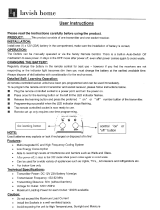
Different Conditions for Installation
Installation
35mm Minimum
Minimum space above the garage door
C-Rail Extension
Bow Arm Conversion
Door Arm Extension
Before installing the operator you should check the garage for the
conditions of installation. You will need optional extras in either of
the following situations:
If the garage door is higher than 2.250 mm you will need a c-rail
extension. Two sizes of extensions are available: 500mm and
1.000 mmm.
The operator may be extended by a maximum of 1.500mm - the
maximum height of a garage door is 4.150mm.
For a canopy type garage door (inside turning door) you will need
a bow arm conversion to automate the door.
Inside turning doors are equipped with a roler on each side at the
bottom of the door. With these rollers the door cannot tilt outside
- an automation without the bow arm conversion is not possible.
Should the minimum space between the garage door and the ceil-
ing be smaller than 35mm then a door arm extension is needed.
For an extension you can use a metal beam from any DIY-market.
The beam should not be shorter than the door‘s height.

(1)
(1)
(2)
(3)
(3)
(4)
6
7
During this procedure be careful not to twist the chain. Therefore
do not lift the parts - slide them along the oor.
1. The operator is laying unpacked in front of you. The motor-
head unit is on your right hand side.
2. Lay part (1) to the front.
3. Fix through pushing the C-prole coupling piece (2) over it all
the way home.
4. Slide C-rail part (3) in front of part (1)
5. Set part (3) in the C-rail coupling piece (4) at an angle, inserting
it from above as shown.
6. Press down part (3) to tension the chain.
7. Turn around the operator and screw in the milled nuts into the
C-rail coupling pieces.
Your operator now is readily premounted for installation.
The chain has been pretensioned in the factory; do not change
the chain tension!
ATTENTION:
The setting of the limit-switches and the automatic-force
adjustment were set for factory testings. When you change
the limit-switch settings you rst have to run a new learn-
ing cycle to make the operator work properly! (Please refer to
the pages 10+11)
Pre-Mounting the operator
Installation

(1)
(2)
(2a)
(3)
(3a)
(4)
(5)
(6)
6
7
Installing the operator
Installation
Meassure the distance between the ceiling and the highest point
reached by the garage door (1).
The minimum-headroom necessary for mounting the operator is
35 mm. If there is less headroom please pay attention to page 5.
The front xing angle can be mounted either at the lintel or at the
ceiling.
1. Meassure the middle of your garage door and make a mark on
the lintel and the top of your door (2+2a).
2. Fix the front xing angle in the middle either at the lintel or at
the ceiling. (We recommend the lintel if possible) (2+2a).
3. Attach the C-rail to the front xing angle (3). Put a carton piece
under the motor head unit to avoid damages.
4. To x the motor head to the ceiling we recommend you to use
a ladder (4). When the operator is laying on the ladder you can
open the garage-door. Adjust the C-rail according to the mark you
made in the middle of the garage-door.
Fix the operator to the ceiling when you have made sure the C-rail
is running straight to the front.
5. Now x the door arm to the garage door (5). Take care that the
angle between the operator and the door arm does not exceed a
max. of 45° (it may be lower).
6. Before running the operator disengage the door‘s lock-
ing-bolts otherwise the operator cannot open the door. This
could result in damage to the operator and/or the garage
door. The self-locking gear of the operator will ensure that the
door cannot be opened manually. If you require additional secu-
rity, ie using door bolts, please ask your dealer for our locking set,
which is available as an optional extra.

8
9
Installation
In case of a power failure the garage door can be opened by
hand. Therefore the operator rst needs to be released.
When the garage door is the only entrance
It is necessary to connect the emergency release to the door‘s
handle (pic. 1) otherwise the garage cannot be accessed in a
power failure situation.
Procede as follows:
1. Find out in which direction the door handle moves when open-
ing the door.
2. Drill a hole in that side of the door handle which turns down-
wards.
3. Thread the cable through the hole and x it with the enclosed
metal-clamps. Be carefull not to put a high tension on the emer-
gency release cable - the operator then might release from the
garage-door during a normal opening cycle.
4. Check the function of the emergency release together with a
second person. Stay inside the garage and close the door with
the operator. Let the second person open the door manually with
the door keys. If this works, the emergency-release is mounted
properly.
Do not leave the garage and close the garage-door with the
operator before you have tested the emergency-release!
The Emergency Release
When there is a second entrance to the garage
You can use the supplied handle for the emergency release (pic.
2).
Thread the emergency release cable through the handle.
Fix the metal clamps to the cable where the handle shall be
placed.
Shorten the cable below the metal clamps - the handle is now be-
ing held by the clamps.
In case of a power failure the user can now open the garage
door by releasing the operator with the handle for the emergency
release.
Pic. 1
Pic. 2

1
2
34
8
9
Devices for Adjustments
Printed Circuit Board: Adjustments and Connections
TEST/RUN-Button (1)
With this button you put the operator into operation. The button
works on the OPEN-STOP-CLOSE principle, e.g. the rst push
opens the door, the second push stops the door and the third
push closes the door etc.
The LED-lamp “TEST“ is switched on as long as you press the
TEST-button and shows that the impulse was received an recog-
nised by the electronics.
LERN/LEARN-Button (2)
This button has to functions:
1. Learning the forces
2. Registering (learning) a hand-transmitter
The LERN/LEARN-button must be pressed for approx. 3 sec.; the
button can be released once the operator‘s light starts blinking.
Whilst the operator‘s light is blinking you can either register a new
hand-transmitter by pushing the hand transmitters button O R
you may start the learning of forces by pressing the button once
again.
Details on both procedures can be obtained from the chapters
“Automatic Force Setting“ and “Remote Control“.
Potentiometer “PRESSURE OPEN/CLOSE“ (3)
With these potentiometers you must adjust the maximum force
for the force learning cycle (please refer to the chapter “Automat-
ic Force Setting“) separately for OPENING and CLOSING direction.
The operator will never override the adjusted forces, neither dur-
ing the learning cycle
nor in later use
!
The maximum forces are shown in %. Dependant on the operator
model this means:
max.force
%age
Operator with
75 kg max.
Operator with
100 kg max.
20% 15 kg approx. 20 kg approx.
50% 37 kg approx. 50 kg approx.
70% 52 kg approx. 70 kg approx.
100% 75 kg 100 kg
Potentiometer “LIGHT“ (4)
With this potentiometer the time for the internal lighting is ad-
justed in seconds. Values from 80 to 240 seconds are adjustable.
This page only shows the functions of the buttons and potentiometers on the P.C.B.. To programme the operator ple-
ase refer to page 10 onwards.

1
2
3
10
11
Limit-Switch Adjustment and Force Measurement
Pictures:
1: TEST/RUN-Button
2: LERN/LEARN-Button
3: Potentiometer for Force Adjustment
Information
To use the operator the following steps must be carried out to
adjust the limit-switches and to learn the required force. Without
these adjustments the operator will only run for the factory
set distance when pressing the TEST-button.
The limit-switch adjustment and the force-learning are both done
in one combined programming step. The operator needs to be set
into programming-mode - the programming-mode is indicated by
the blinking operator’s light. During the programming-mode the
limit-switch setting is done rst, followed by the force-setting.
The procedure of adjustments:
1.) Adjustment of the maximum force for learning-mode
2.) Start of programming-mode
3.) OPENING limit-switch
b.) Adjustment CLOSING limit-switch
4.) Start the learning-cycle for force and distance.
Descriptions of each step will be found in the following text.
1.) Adjusting the maximum force for the learning-cycle
The force adjusted via the potentiometers “FORCE OPEN“ and
“FORCE CLOSE“ determines the maximum forces for the learn-
ing cycle and in later use. The factory setting is 60% for both. On
smaller, easy running doors a force of 40% will be sufcient.
2.) Starting the learning-mode
Press the LERN/LEARN button (2) on the main electronics for
approx. 3 seconds. When the operator’s light begins blinking
- release the LERN/LEARN button.
The operator now runs in learning-mode. The learning-mode
runs without time-limit - there is no need to rush with the
following adjustments.
3.) The Limit Switch Adjustment
In CLOSING-position the garage door shall not be pressed hard
onto the doors‘ frame. If it is pressed too hard then the operator
will reverse after each CLOSING and the garage door will remain
open for approx. 5 cm.
Printed Circuit Board: Adjustments and Connections

10
11
Limit-Switch Adjustment and Force Measurement
Basics: During the learning-mode the operator will follow the
limit-switches automatically when these are moved.
E.g.: The operator hits the CLOSING limit-switch but the garage-
door still is not completely closed. You can now slide the red
limit-switch actuator off the CLOSING limit-switch - the operator
will automatically start running in CLOSING direction until it hits
the CLOSING limit-switch again. You do not have to press the
TEST/RUN button to activate the operator.
The procedure works vice-verca in OPENING direction.
Attention: the operator only follows the limit-switch in ONE
direction - the CLOSING limit-switch is only followed in CLOSING
direction, the OPENING limit-switch is only followed in OPENING
direction.
To run the operator in another direction you have to press the
TEST/RUN button.
The operator’s light will be blinking throughout the whole proce-
dure of setting the limit switch.
3.)a.) Adjusting the OPENING limit switch
1.) Run the operator in OPENING direction using the TEST/RUN
button (1) (the button follows the principle OPEN-STOP-CLOSE
etc., e.g. rst impulse OPEN, second impulse STOP, third impulse
CLOSE etc.)
2.) When the garage door is almost opened to maximum you have
to stop the operator using the TEST/RUN button. Then slide the
OPENING limit switch actuator so that it hits the limit-switch.
3.) When the OPENING limit switch is hit before the garage door is
opened to maximum then simply slide the red limit switch actua-
tor further in OPENING direction - the operator will follow the
movement.
3.)a.) Adjusting the CLOSING limit-switch
1.) Run the operator in CLOSING direction using the TEST/RUN
button (1) (the button follows the principle OPEN-STOP-CLOSE
etc., e.g. rst impulse OPEN, second impulse STOP, third impulse
CLOSE etc.)
2.) When the garage door is closed you have to stop the operator
using the TEST/RUN button. Then slide the OPENING limit switch
actuator so that it hits the limit switch.
3.) When the CLOSING limit switch is hit before the garage door
is closed then simply slide the red limit switch actuator further in
CLOSING direction - the operator will follow the movement.
4.) Starting the learning cycle
Press the LERN/LEARN button after the limit switches are adjusted
properly (the garage-door should then be closed and the CLOSING
limit-switch is actuated).
The operator then starts the automatic learning cycle and will do
three runs:
- OPENING the garage door
- CLOSING the garage door
- OPENING the garage door.
All three runs are done fully automatic.
After the learning cycle the operator will rest in OPENING position
- the operator’s light stops blinking. The operator now is ready
for use. For programming the hand-transmitter please refer to the
chapter “Remote-Control“ on page 16.
Printed Circuit Board: Adjustments and Connections
Quick Reference
1.) Force Adjustment Adjust the maximum force for
OPENING and CLOSING direction
for the learning cycle
2.) Start programming
mode
Press the LERN/LEARN button for
approx. 3 seconds. The operator’s
light begins blinking - release the
LERN/LEARN button
3.) Limit Switch Adjustment a.) Adjust OPENING limit switch
b.) Adjust CLOSING limit switch
(The operator can be run
in OPENING and CLOSING
direction using the TEST/RUN
button)
4.) Start learning cycle The garage door is closed and
the operators hits the CLOSING
limit switch
Press the LERN/LEARN button
shortly
The operator does three runs
(OPENING-CLOSING-OPENING)
The learning cycle stops after the three runs. The garage door
is then opened and the operator’s light stops blinking. The pro-
gramming is now complete.
5.) You may now procede with chapter “Remote Control“ on
page 16

W
W
12
13
The most important connectors
Printed Circuit Board: Adjustments and Connections
Component Connector Function
Push Button and
Key Switch
A + B Floating connector for push button and key switch:no electricity to come into contact
with these connectors!
When using an external receiver the impulse wires are connected to this terminal.
24V DC Supply G + H 24V DC power supply for external components (external receiver, photo-cell), a maxi-
mum of 200 mAmp. is allowed.
230V AC Supply M + N 230V AC power supply for external components. Shortcuts created by external compo-
nents on this connector will inuence the house fuse directly.
Receiver-Module HF-Modul /
Receiver-Card
Plug for Seip remote-receiver cards.
Advanced Connectors
Component
Photo-Cell without selftest:
C + D
(with 8,2 kOhm
resistor)
Wiring:
Photo-Cell with selftest
C + D
(Photo-Cell receiver)
I + J
(Photo-Cell trans-
mitter)
The main electronics provides the possibility of testing the photo-cell before every movement - within milliseconds a malfunc-
tion of the photo-cell is simulated. To enable the main-electronics for this testing the impulse cables of the photo-cells‘ trans-
mitter must be connected to I + J and the impulse cables of the photo-cell’s receiver must be connected to C + D.
ATTENTION! If you want to use this selftest option, you must connect the photo-cell before the limit switch setting
and force adjustment, otherwise there will be no selftest in later use.
Transmitter
Receiver
Transmitter
Receiver

W
W
W
12
13
Advanced Connectors
Printed Circuit Board: Adjustments and Connections
Security Beam and Hatch Door
E + F
(mit 8,2 kOhm
Auswertung)
Function
OPENING direction: when releasing the CLOSING limit-switch the connector is checked for 3 seconds (= hatch door closed or
opened). Impulses coming in later during the OPENING cycle will be ignored.
CLOSING direction: the connector is being checked throughout the whole CLOSING cycle. If an obstacle is recognized (by the
security-beam) the operator will reverse (please also refer to chapter “Special Functions“, paragraph “DIP-Switch 4“, page 15).
Two devices may be connected to this connector:
1.) Security-Beam
This device is normally equipped with a 8.2 kOhm resistor. Therefore you have to remove the 8.2 kOhm resistor from the con-
nectors E + F before connecting the security-beam.
2.) Hatch-Door Switch
A hatch-door within the garage door can be secured with a switch - when the switch is not activated (e.g. the hatch-door
stands open) the operator will not work.
Security Beam (8,2 kOhm resistor connected in line):
Hatch-Door Switch (8,2 kOhm resistor connected in line):
Security Beam and Hatch-Door (connected in line):
Modules for Special Functions
„Versions Mod-
ule“
Plug for optional modules providing special functions:
- Automatic Closing (AZ)
- One-Way traffic control (EI) with traffic-light regulation
- Dead-Man-Function (TO) (push-button needs to be pressed during the whole CLOSING cycle, otherwise the operator stops)
Cycle Counter
L A counter for OPENING/CLOSING cycles can be connected (24V)

14
15
LED-Lamps
Printed Circuit Board: Adjustments and Connections
LED Function ON OFF
LED “TEST“ “ON“ when a device connected to A+B (push-button, key-switch)
or the electronics‘ TEST-button gives an impulse
Incoming impulse No incoming im-
pulse
LED “Diag“ “ON“ when an impulse from a programmed hand-transmitter is
received.
More functions of this LED are named in the chapters “Learning
the force“, “Remote-Control“ and “Error messages“.
Incoming impulse
from a programmed
hand-transmitter
No incoming im-
pulse from a hand-
transmitter
LED “Vp“ “ON“ when mains power supply is o.k. Mains power supply
o.k.
No mains power
LED “SLZ“ Photo-Cell
Possible Errors:
- an obstacle is registered by the photo-cell
- the connection wires might be broken or a short-cut was created
- the photo cell is damaged
- the 8.2 kOhm resistor is not connected properly
Error or obstacle o.k.
LED “LSZ“ Security Contact / Hatch-Door Switch
Possible Errors:
- the security beam registers an obstacle
- the hatch-door is open
- the connection wires might be broken or a short-cut was created
- Security beam or hatch-door switch is damaged
- the 8.2 kOhm resistor is not connected properly
Error or obstacle o.k.
LED “SEZ“ Checks the function of the CLOSING limit switch - when the limit
switch is activated, the LED goes on. If it does not, then the limit
switch is damaged.
activated not activated
LED “SEA“ Checks the function of the OPENING limit switch - when the limit
switch is activated, the LED goes on. If it does not, then the limit
switch is damaged.
activated not activated

DIP
1 2 3 4 5 6
14
15
Printed Circuit Board: Adjustments and Connections
Special Functions
DIP-Switch Settings
DIP-Switch Function ON OFF
1
Automatic Force Measurement
Standard setting: ON
ATTENTION! In countries of the European Union the operator must be run with automatic
force measurement - running it on manual force is illegal!
In non-European countries the manual force may be used. Please pay attention to the fact, that the
learning cycles (chapter “Limit-Switch Settings and Force Adjustment“, pages 10+11) must also be done
when manual force is chosen!
Yes No
2
Additional Force
Standard setting: ON
For very light garage doors we recommend to set the switch to OFF
Yes No
3
Pre-Warning light before every movement
Standard setting: OFF
When choosing ON a pre-warning of appox. 4 sec. will be made before each movement of the garage
door.
Yes No
4
Full reversion in OPENING direction
Standard setting: ON
The operator reverses approx. 20 cm when an obstacle in CLOSING direction is recognised. If the switch
is set to ON the operator will reverse completely in OPENING direction until the OPENING limit switch is
reached.
Yes No
5
No reversion on Security-Beam when door closed
Standard setting: ON
This function is only needed when a security-beam is connected. In garages with an uneven floor the
security-beam might lead to unwanted reversion when the garage door is almost closed. If the switch is
set to ON the revertion in SOFT-STOP will be prevented - the operator simply stops and the door remains
closed.
HINT! Using this function might lead to problems programming new hand-transmitters via an existing
hand-transmitter. For that programming the operator needs to hit the CLOSING limit-switch. Please also
refer to chapter “Remote Control“
Yes No
6
Side Hinged Doors
Standard setting: OFF
For use with a side hinged door the OPENING and CLOSING directions need to be reversed - setting this
switch to ON will do that automatically.
Yes No

16
17
Remote Control
Programming the Hand Transmitters
Basics
As a standard the operator is equipped with a 433 MHz AM
remote control set. The coding is done via rolling code - the code
is changed after each impulse; receiver and transmitter agree com-
pletely automatic about the next code to be used. New codes will
be chosen out of a pool of billions of possible codes.
Your operator is equipped with our standard remote control set
when you hand transmitters looks like the one shown on the right
hand side. The 4-channel MIDI transmitter is standard equipment,
the 2-channel MINI transmitter is available as an optional.
If your operator is equipped with another remote control set,
please refer to the manufacturers instructions for programming.
Programming Transmitter and Receiver
To use a hand transmitter it must rst be registered (programmed)
by the receiver. Only one hand transmitter button can be used for
one receiver.
Registering the rst hand transmitter
The rst hand transmitter (e.g. no hand transmitter has been
registered for the receiver, yet) must be learned directly via the
operators‘ main electronic:
1. Press the LERN/LEARN button on the main electronic for approx.
3 seconds until the operator’s light starts blinking and release the
LERN/LEARN button.
2. Press the hand transmitter button you want to register to the
receiver - the operators’ light stops blinking when the transmit-
ters’ signal was received. The transmitter is now registered.
Registering additional hand transmitters
When at least one hand transmitter has been registered by the
receiver you may program additional hand transmitters from a
distance:
1. The garage door must be closed
2. Open the garage door approx. 50 cm and close it again.
3. After the garage door is closed you have got 10 seconds to
press the buttons 1+2 simultaneously on the registered hand
transmitter - the operator’s light then starts blinking.
4. The light will keep blinking for another 10 seconds - during that
period of time you must press the button on the new hand trans-
mitter which you want to use with the operator. Once the new
transmitter is registered the operator’s light stops blinking.
The procedure must be repeated for each new hand transmitter.
Clearing the receivers‘ memory
Keep the LERN/LEARN button pressed for approx. 15 sec.. The
operators‘ light and the red LED „Diag“ will start blinking after 3
seconds. After another 10 seconds the red LED „DIAG“ will glow
constantly. You can then release the LERN/LEARN button.
All previousely programmed hand transmitters are now
cleared from the receivers‘ memory.
Quick reference: programming the rst hand transmitter
1.) Keep the LERN/LEARN
button pressed for approx.
3 sec.
The operators‘ light will start
blinking
2.) Press the hand transmit-
ter button you want to use
The operators‘ light stops
blinking - the transmitter was
succesfully programmed
Quick reference: Programming additional hand transmit-
ters from a distance
Remark: additional hand transmitters can be programmed
either like the rst transmitter or from a distance as explained
below:
1.) Open the garage door
for approx. 50 cm and close
it again
After the garage door is closed
you have got 10 seconds to pro-
ceede to step 2)
2.) Press buttons 1+2
simultaneousely on any
registered transmitter for
3 sec.
The operators‘ begins blinking
- release the hand transmitters‘
buttons
3.) Take the new hand
transmitter and press the
button you want to use
shortly
The operators‘ light stops
blinking - the hand transmitter
was successfully programmed

1
2
3
4
16
17
Remote Control
4-channel MIDI transmitter,
433 MHz, rolling code
2-channel MINI transmitter (optional extra),
433 MHz, rolling code
Battery
Usable types of batteries: A23, 23A, 23L, EL12, VR 22 and
MN 21
Voltage: 12V
Used batteries must be disposed according to national
laws!
Two batteries, type CR1616 or DL1616 are required.
Voltage: 2* 3V (=6V)
Used batteries must be disposed according to national
laws!
Two Batteries
Criterias inuencing the range
The TS operators are equipped with a high quality remote
control set as a standard!
Nevertheless the remote control is the part of the operator which
might be inuenced by circumstances in the surroundings of the
garage. With our standard remote control you might reach a
range of more than 100 meters. In areas with high disturbancies
the range will still be approx. 50 meters.
The range might be inuenced by:
- old batteries in the hand transmitter - if you should experience
a problem with the range, please change the batteries rst. The
lower the batteries run the lower the range will be.
- Building materials of the garage
In a garage made of concrete and steel you might reach a lower
range than in an ordinary garage build of stone. The more steel
was used for the walls the shorter the range of your remote-con-
trol.
Remote-control activity in the area
Radio and television transmitters close to your garage might
reduce the range.
Older baby-phones
Especially older baby-phones might inuence the range of the
remote control severely. These devices send strong signals via the
houses internal power supply net. These signals also intrude other
devices via the wall plug, as eg the operator.
It is extreemely unlikely that the range will drop to an unaccept-
able distance. If, however, problems should occure we will like to
be helpful.
Please avoid to drop the hand transmitter - parts could
be damaged inside the transmitter. That might lead to
malfunctions!
Additional Information
Use with a HomeLink© System
The HomeLink© System is becoming more and more popular in
private households. Most frequently it is being used in cars - the
HomeLink© module is integrated in the car. It allows the driver to
activate the door operator with a push of button which is installed
in his car. Once programmed, the driver does not need the hand
transmitter to access the garage with his car.
The standard remote control supplied with the TS-series is com-
patible with HomeLink© systems manufactured by end of year
2002 / beginning of year 2003 (subject to technical alterations).
The procedure how to program the HomeLink© device is de-
scribed in the car‘s manual - please refer to those instructions.
(Basic information on programming: you rst must register
the hand transmitter with the operator. The HomeLink©
system will then learn the code from the hand transmitter).

18
19
TS 75 TS 100
Maximum Pulling Force (adjustable) 70 kg (+/- 4%) 100 kg (+/- 4%)
Force-Setting for Operation automatic automatic
Motor 24V DC, low-noise 24 V DC, low-noise
Running Speed 14,5 cm/sec. 14,5 cm/sec.
Speed in Soft Mode 8 cm/sec. 8 cm/sec.
Lighting 230V AC, max. 40 watts 230V AC, max. 40 watts
Lighting Durance (adjustable) 80 to 240 seconds 80 to 240 seconds
Duty Cycle 80% 80%
Power Consumption in Stand By 2,3 watts 2,3 watts
Power Supply 190-250V AC 190-250V AC
Transformer 230V AC, 24V DC 230V AC, 24V DC
Pre-Warning Light adjustable adjustable
Stop on Security Beam in Closing Direction adjustable adjustable
Automation of Side Hinged Doors adjustable adjustable
Nett Running Length 2.640 mm 2.640 mm
Max. Running Length with Extension 4.150 mm 4.150 mm
Overall Length 3.215 mm 3.215 mm
Height Motor Head 170 mm 170 mm
Length Motor Head 370 mm 370 mm
Width Motor Head 260 mm 260 mm
Minimum Space above the door 35 mm 35 mm
Weight including packaging 22 kg
Technical Data
For the TS-series operators we provide plug-on module cards for
advanced functions:
Module “Automatic Closing“ (AZ)
For automatic closing of the garage after an adjustable time from
80 to 240 seconds.
The card is also equipped with a connector giving an impulse for
one second when the garage door is opened - an automatic exter-
nal light can be connected here.
Special functions as “fast closing“ (the garage door will be closed
as soon as the car passed the photo cell) and “additional photo-
cell in opening direction“ are adjustable on the module-card.
Module “Separated Impulse“ (TO)
The impulses for OPENING and CLOSING direction are given sepa-
retely - one button will always OPEN the door and the other will
allways CLOSE it. It can be adjusted so either direction will work
on impulse or steady press of the button (e.g. the button needs to
be pressed for the whole OPENING or CLOSING cycle - when the
button is released the door stops)
Module “One Way Trafc Control“ (EI)
A trafc control for narrow access to/from a garage. Red and
green trafc lights can be connected.
Installation and User manuals are enclosed to the modules.
Technical Information
Optional Special Functions
Sample: Modul for automatic closing
with potentiometer for adjustment of
the opening time.

18
19
Wiring
Technichal Information
Internal Wiring
1 Blue, mains supply, 230V
2 Brown, mains supply, 230V
3 Black, transformer, 230V
4 Black, transformer, 230V
5 Brown, Lighting, 230V
6 Blue, Lighting, 230V
7 White, transformer, 24V
8 White, transformer, 24V
9 MOTOR Connector for the plug from the motor
K Connector for the plug from the limit switches
PE Earthing from the printed circuit board to the
base plate
Earthing of
the mains
supply
The earthing of the mains supply (green/yellow)
is connected to the base plate with a screw (the
screw is marked with a earthing symbol)
External connections
(Explained on pages 12 + 13)
A + B Floating connector for push-button, key-switch
and the impulse cables of an external receiver
C + D Floating connector with a 8,2kOhm resistor for
impulse cables from a photo-cell receiver
E + F Floating connector with a 8,2 kOhm resistor for
security beam and hatch-door switch
G + H 24V DC supply for external components (max.
200 mAmp.)
I + J 24V DC for a photo cell transmitter when a
self test before every movement of the door is
required
L Connector for a cycle counter (24V) - all open-
ings will be counted
M + N 230V AC for external components - not secured
by the electronics. Shortcuts will blow the
house fuse.
Other
HF-Modul/Receiver
Card
Plug for receiver module, 433 MHz
Versions-Modul Plug for modules for special functions
FUSE Fuse T1,6, 250V
Devices for adjustments
Potentiometer
„Licht/Light“
Adjustment of the time for the internal
lighting (60-240 Sek)
Potentiometer
„Force Open“
Adjustment of the maximum force for the
opening direction
Potentiometer
„Force Close“
Adjustment of the maximum force for the
closing direction
Button
„Test/Run“
Runs the operator - OPEN-STOP-CLOSE
Button
„Lern/Learn“
For automatic force setting and registration
of hand transmitters

4
5
1
3
1
7
1
1
0
7
8
18
1
6
9
8
3
1
5
1
2
6
2
28
26
27
25
30
22
23
31
20
21
19
28
24
29
20
21
Spare Parts
Technical Information
No. Description Stock-Code
19 Chain PM0301
Chain Closing Link PM0310
20 Chain Tensioner PH2200
22 Carriage PH2600
23 Door Arm PH2403
24 Bowden Cable M07000
25 Guide Pulley Holder PM12002
26 Guide Pulley PI0120
27 Fixing Square PM04003
28 Chain Guide Block PI0502
29 C-Profile Coupling Piece PM1400
C-Rail, 1m PH3000
No. Description Stock-Code
1 Motor TS 75 PL1212
Motor TS 100 PL1312
2 Transformer PL2006
3 Printed Circuit Board PE05004
4 Lampholder PH2101-1
5 Light Bulb PJ0530
6 Power Supply Cable PJ0450
7 Limit Switch Unit PH0830
8 Limit Switch Actuator PI1200
9 Spur Toothed Wheel PH3201
10 Step Wheel PI0105
12 Cover PI0006
No. Description Stock-Code
13 Light Cover PI0005
15 Threaded Distance Piece PI0310
16 Twisted Nipple PI1311
17 Pinion TS 75 PM11006
Pinion TS 100 PM11005
18 C-Shaped Part PH1500
/