Page is loading ...

V01-01 SOLDEC16
Please read these instructions carefully!
We disclaim all liability under the terms of the warranty for any damage caused by improper installation!
Approved according to the European Directives 89336 EEC and 73/23 EEC
Installation Instructions
for Automatic Garage Door Operators
Solar FR I
GB

(1)
2
(2)
(2)
(1)
(3)
(3)
(4)
(1)
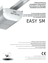
Sketches on the left-hand side:
If the operator is to be fixed to the ceiling using the fixing-brackets in front of the
motor-head (looking from inside the garage to the garage door), then the fixing-profile
must be slid over the rail before premounting the whole rail. If the operator is to be
fixed to the ceiling from behind/above the motor-head the fixing-profile can be slid
over after the pre-assembly procedure.
During this procedure be careful not to twist the chain. Therefore do not lift the
parts; slide them along the floor.
1. The operator is laying unpacked in front of you. The motor-head unit is on your
right hand side.
2. Lay part (1) to the front.
3. Fix it through pushing the C-profile coupling piece (2) over it all the way home.
4. Slide C-rail part (3) in front of part (1)
5. Set part (3) in the C-rail coupling piece (4) at an angle, inserting it from above as
shown.
6. Press down part (3) to tension the chain.
7. Turn the operator over and screw in the milled nuts into the C-rail coupling pieces.
Your operator now is assembled for installation.
The chain has been pretensioned in the factory; do not change the chain tension!
ATTENTION:
The limit-switches of your operator have been put to a factory position. Do not change
this limit-switch adjustment until the operator is fitted to the ceiling and the garage-
door!
Otherwise the carriage could crash into the motor-head unit when the operator is
running without being fitted!
This would cause great damage to your operator!
(1) If the minimum headroom above the garage door is less than 35 mm (see page 4)
you need a door-arm extension. The operator then must be mounted in the rear of
your garage.
(2) If your garage-door is higher than 2.25m a C-rail extension-piece is required.
Otherwise the garage-door will not open completely.
1. Make sure, that your garage-door runs smoothly. If necessary grease or oil certain
parts.
2. The enclosed fixing-material will be satisfactory for a standard-garage.
3. To explain the Fitting procedure we are using an up-and-over-door in this
handbook. The procedure remains the same for other types of door.
4. Pay attention to page 10 "Safety Instructions“
2 PRE-MOUNTING
1 BEFORE GETTING STARTED...

3
(3)
(1)
(2)
(4)
(5)
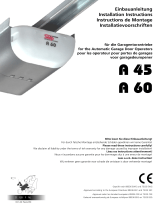
Before fitting the operator to the ceiling we recommend you detach the motor-
head unit; mounting the C-rail will then be easier. You will find the instructions on
how to detach the motor-head on page 4.
Measure the distance between the ceiling and the highest point reached by the
garage door (1).
The minimum headroom necessary for mounting the operator is 35 mm. If there is
less headroom please pay attention to page 2.
The front fixing-angle can be mounted either on the lintel or on the ceiling.
1. Measure the middle of your garage-door and make a mark on the lintel and
the top of your door.
2. Fix the front fixing-angle in the middle- either on the lintel or on the ceiling.
(We recommend the lintel if possible).
3. Attach the C-rail to the front fixing-angle (4). Put a piece of cardboard under
the motor-head unit to avoid damage.
4. To fix the motor-head to the ceiling we recommend you use a ladder (5). When
the operator is laying on the ladder you can open the garage-door. Adjust the C-
rail according to the mark you made in the middle of the garage-door.
Fix the operator to the ceiling when you have made sure the C-rail is running
straight to the front.
5. Now fix the door-arm to the garage-door. Take care that the angle between
the operator and the door-arm does not exceed a max. of 45° (it may be less).
6. Before running the operator dismount the doors locking-bolts! Otherwise
the operator cannot open the door and this will lead to damage to your
operator and the garage door.
If you would like additional security you can have door bolts fitted; please ask
your dealer about our locking set, which is available as an optional extra.
MOUNTING 3

4
4 CONNECTING THE BATTERY
To prevent the battery from discharging while in stock the Solar FRI is delivered with
one disconnected battery cable. To use the operator this cable must first be plugged
onto the open battery connector (please refer to the sketches aside) - or else the
operator will not work.
ATTENTION! The batteries are delivered fully charged - the capacity will allow up to 80
openings/closings. All the necessary adjustments during the installation can therefore
be made easily (generally 5 to 20 openings/closings). Nevertheless it is recommended
to avoid any unnecessary operation. If, however, the low-voltage indicator becomes
active (e.g. the battery-capacity is about to fall below the necessary minimum voltage)
then the operator automatically switches off until the batteries have been completely
recharged (by the solar panel)!
5 ATTACHING AND DETACHING THE MOTOR HEAD
The sketches on the left show the attachment-procedure.
For the easier mounting of the C-rail (please refer to page 3) and to exchange the
batteries we recommend you detach the motor head from the C-rail.
The motor head is held in position by two fixing brackets. The brackets are secured by
one fixing-screw each. Loosening the fixing-screws enables the brackets to be turned -
procede as follows (the operator is lying in front of you, the housing is facing towards
you):
1. Slightly lift the fixing-brackets (away from the base-plate) - turn them to release the
C-rail.
2. Turn the motor-head counter-clockwise as far as possible
3. Pull the motor-head upwards to disconnect it from the C-rail.
To attach the motor-head to the C-rail please follow the procedure as shown in the
sketches on the left. Tighten the screws in the fixing-brackets to stop the brackets
turning by accident.
ATTENTION! The fixing-brackets are connected to electronic security-switches. If the
motor-head is not attached and fixed correctly to the C-rail the electric circuit is broken
- the operator will not work!
If, however, the motor-head starts turning after several operations because of
incorrect fixing then the electric circuit will be broken as well and the operator will not
work until the problem has been fixed.

5
In case of a power-failure or an error with the operator you can open your garage
door manually. Therefore the operator must be disconnected from the garage
door.
If your garage has a separate entrance:
You may leave the Bowden-cable as it is. In the above mentioned cases you can
pull the cable to disconnect the operator from the garage door. To connect it
again, just switch on the operator.
If your garage door is the only entrance to your garage:
You have to connect the emergency release to your door-handle. Otherwise you
will not be able to open your door in one of the above mentioned cases.
Follow these steps:
1. Figure out in which direction the door-handle moves when opening the door.
2. Drill a hole in that side of the door-handle that turns downwards.
3. Thread the cable through the hole and fix it with the enclosed metal-clamps.
Be carefull not to put a high tension on the Bowden-cable - the operator then
might release from the garage-door during a normal opening-cycle.
4. Control the function of the emergency release together with a second person.
Stay inside the garage and close the door with the operator. Let the second
person open the door manually with the door-keys. If this works, the emergency-
release is mounted properly.
Do not leave the garage and close the garage-door with the operator before
you have tested the emergency-release!
EMERGENCY RELEASE 7
LIMIT SWITCH SETTING 6
Your garage door opener automatically stops when one of the red limit-switch
actuators trips a limit-switch (in either CLOSING or OPENING direction).
Adjust the limit-switches by hand.
OPENING direction
Please set the limit-switch actuator for the OPENING direction so that the door
comes to a halt about 30 mm (1.2") before its final resting position.
CLOSING direction
Please set the limit-switch actuator for the CLOSING direction so that the door
lightly touches the door frame when closed.
ATTENTION:
Fit the operator completetly to the garage-door before changing the limit-switch
position.
Even if the limit-switches are then adjusted wrongly, the operator will be stopped
by the garage doors stop-points.
Changing the limit-switch position without having fitted the operator to the
garage-door can lead to the destruction of the operator, when the carriage runs
into the motor-head unit!
Adjusting the OPENING limit-switch incorrectly (e.g. the limit-switch OPEN never
gets activated) will lead to the operator switching off because of increasing
pressure. This will sooner or later lead to damage of the gear - the life-cycle of
the operator decreases dramatically!
Adjusting the CLOSING limit-switch wrongly will lead to the door opening because
of the increasing pressure.
If the door fits too tightly in the frame when closed, the emergency-release will
be difficult to use.

6
8 THE SOLAR PANEL
South
The cable should rise slightly from
the outside to the inside of the
garage
Together with the Solar FR I you receive a solar panel and a fixing-bracket (in 2 parts).
The panel transforms solar energy into electricity which is used to recharge the
batteries. With a supply of 7 Watts the panel is sufficient for the average day light all
year for most European countries.
If, however, the battery should run low (due to exceptionally heavy use) the low-
voltage protector becomes active. This will be indicated by a beeping tone - once this
tone has started you may use the operator for another two operations. Then the
operator will automatically be switched off until the batteries are fully recharged (the
recharging is done automatically by the operator - the user does not have to do
anything). During this recharging period the operator cannot be used. The recharging
is completed when the operator reacts again to signals from the hand-transmitter or
push-button.
rubber bumpers
Fix the solar-panel to the bracket using the rubber-bumpers as shown in the sketches
on the left. The cable-connector must be positioned upwards. Two screws help keep
the correct distance from the ground.
.
Screws holding the panel
in the correct distance
from the ground
To make the solar-panel work efficiently it should be adjusted to south as precisely as
possible - the more exact it faces south the better the output. The correct angle of
60° is held by the bracket.
Run the cable (total length: 7m) into the garage from the outer wall of the garage (do
not run it directly through the ceiling!). Make sure the cable rises from the outside to
the inside of the garage to keep water from flowing inside.
brown cabel = +
blue cabel = -
Connectors for the solar-panel
On the P.C.B. you will find two connectors to connect the solar-panel - they are
marked „Solar“.
IMPORTANT:
Connect the brown cable to the connector marked „
+“
Connect the blue cable to the connector marked „
-“
ATTENTION: if the cables are interchanged the batteries will not be recharged by the
solar-panel!

7
FORCE ADJUSTMENT 9
The force needs to be adjusted separately for OPENING and CLOSING direction.
To get the forces right you might need a couple of tries. Please take your time for
these adjustments. You should not use more force than necessary to operate your
door (danger of injuries)!
Therefore please reduce both forces first. The operator will then stop during the
operation when the door gets too heavy. In this case you have to increase the
force one tiny step and run the operator again. Repeat this procedure until the
operator can completely open and close the door without stopping in between.
The force potentiometers:
For CLOSING direction: ZU
For OPENING direction: AUF
(Right turn: increasing force, left turn: reducing force)
OPENING Force CLOSING Force
CONNECTORS ON THE P.C.B. 10
External Wiring:
(Connectors that are needed or may be used during the installation)
Solar-panel
brown (+) on connector "Solar +“
blue (-) on connector "Solar -“
Push-Button/Key-Switch
Connector "Taster“
Connection with two cables, only resistance-free components, no electricity may
be brought onto the board.
When the operator is in standby mode (e.g. the operators lighting is off) it must
be switched on with the first impulse (e.g. press of the push-button, hand-
transmitter etc.) - on the second impulse the operator will start working.
Photo-Cell
Connector "SI-2“
If no photo-cell is connected the bridge between the connectors must remain -
without the bridge the operator does not work.
When connecting a photo-cell the bridge must be removed and the two impulse-
wires coming from the photo-cell must be connected.
24V/DC power-supply for external components
Connectors "SI-1“
This connector supplies voltage as long as the operator is switched active (e.g.
the operators’ lighting is on) - it can therefore not be used for external remote-
receivers!
Internal Wiring:
(Only needed to replace internal components, for example the batteries)
Batteries
black (-) on connector "Bat. 24V -“
red (+) on connector "Bat. 24V +“
Lighting
Two blue cables on connector "Licht“
Motor
red on connector "Motor“, outer connector
green on connector "Motor“, inner connector
Do not interchange the red and green cable - or the motor works contrary to the
electronics software - the security features will then not work correctly (e.g. the
automatic reversion when hitting an obstacle in CLOSING direction)
Fixing-Brackets for motor-head unit
Two black cables coming from the security-switch to connector "SI-1“
The operator will not work unless:
1. the security-switch is not connected and
2. the security-switch is not pressed by the fixing-bracket
Motor, green
Motor, red
Lighting
2x blue
Battery cable, red (+)
Battery cable, black (-)
Solar-Panel, brown (+)
Solar-Panel, blue (-)
Push-Button
24V DC power-
supply for external
components
Security switch
motor-head
Photo-Cell

8
A
B
C
D
11 REMOTE-CONTROL
A - Receiver-module (HF-module)
Determines the frequency used (e.g. 40 or 433 Mhz)
B - Decoder board
Determines the coding-system: 12-bit or rolling code
(Description on the reverse side board:
Lern 12-bit = 12-bit decoder
Lern Rol. = rolling code)
C - MIDI transmitter, rolling-code
D - MIDI transmitter, 12-bit
Difference: 12-bit and rolling code
A 12-bit remote-control can be identified by the 10 or 12 switches on the inside of a
hand-transmitter (C). With those switches you can set any code you like - they provide
a maximum of 4096 different codes.
On a hand-transmitter with rolling-code no adjustments can be done. Transmitter and
receiver will change the code every time the hand-transmitter’s button is pressed. The
system will always pick one code by chance out of a pool with billions of different
codes.
Standard equipment is a remote-control set with rolling-code on 433MHz - dependant
on the distribution line another remote-control might have been delivered to you.
Please ask your dealer.
Adjusting the antenna (not for 433 MHz)
Fully unroll the antenna and try putting the antenna in different directions (to the
back, to the front, to the side of the garage) and choose the position where the result
is the best. Avoid putting the antenna in contact with metal or electrical wires
(otherwise the range might be reduced dramatically).
433 MHZ RECEIVER-MODULE
Using a 433 MHz receiver-module the antenna must be shortend to a length of
approx. 35cm. Otherwise only a short range can be reached. The antenna can be left
inside the motor-head unit.
Our standard receivers are self-learning: the code is simply transmitted from the
transmitter to the receiver. The receiver will save the code in its memory.
Clearing the receiver’s memory
ATTENTION: for testing purposes there is a factory-code saved in the receiver’s
memory; this code must be cleared out of the memory first!
Press the button on the decoder-board for approx. 10 sec.. You can release the button
when the LED-light goes on; the memory then is cleared.
Coding the hand transmitter (only applies to 12-bit remote-controls)
If your operator has been delivered with a 12-bit remote-control you must set up a
code on your hand transmitter first. Open your transmitter (as shown on drawing C)
and set the switches to any code you like (avoid putting all the switches to ON or
OFF). After you set up the transmitter’s code you can start sending the code to the
receiver.
Sending the code from the transmitter to the receiver
1. Briefly press the button on the Decoder-board (B). The LED-lamp starts flashing.
2. Press the hand-transmitter button you want to use with the receiver. (Do not go too
close to the receiver). The LED-lamp starts flickering when the signal receiver
recognizes the incoming signal. The LED will go off after a short while and the
operator will start running; your hand-transmitter has then been programmed
successfully into the receiver. You can now activate your operator with the hand-
transmitter.
Maximum quantity of hand-transmitters
The 12-bit receiver allows a maximum of 5 different codes. E.g. you can use as many
transmitters with the same code as you like, but only 5 with different codes.
The receiver with rolling code allows a maximum of 16 transmitters to be used.
Using the hand-transmitter
The solar operator will cut the power-supply for the main-electronics in stand-by mode;
only the receiver is supplied with voltage. Two impulses are needed to operate the
door: the first impulse will switch on the main electronics, the second impulse will
make the operator run.
Therefore you must either
1.) press the hand-transmitters’ button twice quickly or
2.) press the hand-transmitters’ button for approx. 3 seconds
to open the garage door.
As long as the operators’ lighting stays on only one press of the hand-transmitter’s
button is required to set the operator in motion.
This procedure is the same for push-buttons, key-switches and other external control-
devices - the first impulse switches on the operator, the second sets the operator in
motion.

9
TECHNICAL DATA 12
Technical Data
Solar FR I
Motor 24V DC, low-noise
Gear self-locking, 70kg
Running Speed 13 cm/sec.
Max. OPENING-CLOSING force 75 kg
Power Supply Solar/Battery Lead-Gelly, 24V
Lighting 24V, 15W, 1.5 min./Cycle
Lighting Duration 90 sec.
Energy-Management permanent supply
Use 5 OPENING/CLOSING Cycles/Day
Solar-Panel 7 Watt/polycrystallin
Battery 7.2Ah (20 h), 2 units à 12V
Power Consumption in Stand-By 2.6 mAmp.
Batteries’ Spare Energy 15 Days
Minimum Sunlight 0.87 kWh/m
2
x day
Panel Position 60° (south +/-10°)
Low Voltage Protector yes, with sonic indication
Overload Protector yes, constructionwise
Nett running Length 2,640 mm
Overall Length 3,215 mm
Motor-Head Height 170 mm
Motor-Head Length 370 mm
Motor-Head Width 260 mm
Min. Headroom above Door 35 mm
Weight 25 kg
Solar-Panel
Positioned in a southerly direction with an angle of 60° (held by the supplied
metal-bracket) a daily sunlight of 600 Wh/m
2
is required to recharge the battery.
Information: the average sunlight in December in Brimingham is approx. 800 Wh/
m
2
, 33% higher than required.
Batteries
The expected life-time of the batteries is approx. 7 years.
Low Voltage Protection
Should the battery capacity show a critically low voltage then an automatic low
voltage protector becomes active.
If, however, the battery should run low (due to exceptionally heavy use) the low-
voltage protector becomes active. This will be indicated by a beeping tone - once
this tone has started you may use the operator for another two operations. Then
the operator will automatically be switched off until the batteries are fully
recharged (the recharging is done automatically by the operator - the user does
not have to do anything). During this recharging period the operator cannot be
used. The recharging is completed when the operator reacts again to signals from
the hand-transmitter or push-button.

13 SAFETY INSTRUCTIONS
Important Safety Instructions for Installation
WARNING: INCORRECT INSTALLATION CAN LEAD TO SEVERE INJURY
Follow all Installation Instructions.
- Before installing the drive, remove unnecessary ropes from the existing installation
- If possible, install the drive at a height of at least 2.10 m and the manual release at
a height less than 1.80 m
- Locate the control actuator within sight of the door but away from moving parts and
at a minimum height of 1.50 m
- Fix the label warning against entrapment next to the control actuator
- The label fixed to the manual release may not be removed
- After installation, ensure that the mechanism is properly adjusted and that the drive
reverses when the door contacts a 40 mm high object placed on the floor.
Important Safety Instructions
WARNING - IT IS VITAL FOR THE SAFETY OF PERSONS TO FOLLOW ALL
INSTRUCTIONS
Keep these Instructions
- Do not allow children to play with door controls. Keep remote controls away from
children.
- Watch the moving door and keep people away until the door is completely closed.
- Use caution when operating the manual release with the door open since it may fall
rapidly due to weak or broken springs. Details on how to use the manual release will
be given.
- Frequently examine the installation for signs of wear, damage or improper balance.
Do not use before repair or adjustment.
- Each month check that the drive reverses when the door contacts a 40 mm high
object placed on the floor. Recheck after adjustement.
To change the bulb unplug the power cable and then take off the small housing on
the front of the operator.
The operators’ case may only be taken off by a professional installer. If your
operator does not work refer to a professional installer. Repairs and replacing
parts may only be done by a professional installer.
!!
!!
!
www.seip.com

11
Grombacher Straße 83
75045 Walzbachtal-Jöhlingen
Germany
www.seip.com
Walzbachtal, 17.04.2001
EG-Konformitätserklärung
gemäß dem Gesetz über Funkanlagen und
Telekommunikationsendeinrichtungen (FTEG)
und der Richtlinie 1999/5/EG (R&TTE)
EC Declaration of Confirmity
in accordance with the Radio and
Telecommunications Terminal Equipment Act
(FTEG) and Directive 1999/5/EC (R&TTE
Directive)
We,
Wir,
Seip Antriebstechnik
Grombacher Straße 83, 75045 Walzbachtal-Jöhlingen, Deutschland
declare that the product
erklären, daß das Produkt
433 RC AM
Hand-Transmitter as remote-control for garage door operators
Handsender als Fernbedienung für Garagentorantriebe
(Short Range Device)
(Funkgerät geringer Reichweite (SRD))
complies with the essential requirements of §3 and the other relevant provisions of the FTEG (Article 3 of the R&TTE Directive), when used for its intended
purpose.
bei bestimmungsgemäßer Verwendung den grundlegenden Anforderungen des §3 und den übrigen einschlägigen
Bestimmungen des FTEG (Artikel 3 der R&TTE) entspricht.
§3(1)1, (Article 3(1)a)) does not refer to this type of product.
§3(1)1, Artikel 3(1)a) bezieht sich nicht auf diesen Produkttyp, es gibt hierzu keine Norm
Protection requirement concerning electromagnetic compatibility §3(1)(2), (Article 3(1)(b))
Schutzanforderungen in Bezug auf die elektromagnetische Verträglichkeit §3(1)2, Artikel 3(1)b))
EN 300 220-1/1997
EN 300 683/1997
EN 60950:2000
NSR / Low Voltage Directive 73/23/EEC;93/68/EEC
EMV / EMC Directive 89/336/EEC;92/31/EEC;93/68/EEC

12
/