Page is loading ...
Dell Global Solutions Engineering
Revision: A01
May 2012
Implementing SharePoint Server 2010
on Dell vStart Solution
A Reference Architecture for a 3500 concurrent users SharePoint
Server 2010 farm on vStart 100 Hyper-V Solution.

Implementing SharePoint Server 2010 on Dell vStart Solution - A Reference Architecture for a
SharePoint Server 2010 farm on vStart 100 Hyper-V Solution
ii
This document is for informational purposes only and may contain typographical errors and
technical inaccuracies. The content is provided as is, without express or implied warranties of any
kind.
© 2012 Dell Inc. All rights reserved. Dell and its affiliates cannot be responsible for errors or omissions
in typography or photography. Dell, the Dell logo, and PowerEdge are trademarks of Dell Inc. Intel and
Xeon are registered trademarks of Intel Corporation in the U.S. and other countries. Microsoft,
Windows, and Windows Server are either trademarks or registered trademarks of Microsoft Corporation
in the United States and/or other countries. Other trademarks and trade names may be used in this
document to refer to either the entities claiming the marks and names or their products. Dell disclaims
proprietary interest in the marks and names of others.
May 2012| Rev A01

Implementing SharePoint Server 2010 on Dell vStart Solution - A Reference Architecture for a
SharePoint Server 2010 farm on vStart 100 Hyper-V Solution
iii
Contents
Executive summary ....................................................................................................... 5
Introduction ................................................................................................................ 6
Microsoft SharePoint Server 2010 ...................................................................................... 6
Dell vStart solution ..................................................................................................... 7
SharePoint on vStart ...................................................................................................... 9
Solution architecture ................................................................................................ 10
Network architecture ................................................................................................ 12
LAN architecture ................................................................................................... 13
SAN architecture ................................................................................................... 15
SharePoint farm configuration ..................................................................................... 17
Configuration of Web Front-End (WFE) servers ............................................................... 18
Search service application configuration ................................................................... 18
Network configuration ......................................................................................... 19
Configuration of the database server .......................................................................... 19
Memory configuration .......................................................................................... 20
Key considerations ...................................................................................................... 21
Summary .................................................................................................................. 21
References ................................................................................................................ 22
Tables
Table 1 High level overview of vStart offerings ...................................................................... 8
Table 2 Hardware configuration of hypervisor servers ........................................................... 10
Table 3 SharePoint 2010 farm role placement and failover configuration .................................... 11
Table 4 VLAN to virtual switch mapping - LAN ..................................................................... 14
Table 5 OS and software editions .................................................................................... 17
Table 6 Virtual Machine (VM) configuration ........................................................................ 17
Table 7 SharePoint database volumes ............................................................................... 20

Implementing SharePoint Server 2010 on Dell vStart Solution - A Reference Architecture for a
SharePoint Server 2010 farm on vStart 100 Hyper-V Solution
iv
Figures
Figure 1 vStart 100 solution components ............................................................................. 9
Figure 2 SharePoint 2010 on vStart - High level architecture overview ....................................... 11
Figure 3 LAN network architecture - High level overview ....................................................... 14
Figure 4 SAN Network architecture - High level overview ....................................................... 16
Figure 5 Search Service Application - architecture ............................................................... 19

Implementing SharePoint Server 2010 on Dell vStart Solution - A Reference Architecture for a
SharePoint Server 2010 farm on vStart 100 Hyper-V Solution
5
Executive summary
A Microsoft® SharePoint® Server 2010 farm hosts the core platform services and applications that
enable multiple capabilities for its users. Since its deployment usually employs a multi-tier
architecture, it is important that the IT decision makers and administrators carefully plan to ensure
service availability and accommodate future growth.
This paper discusses the implementation of a virtualized SharePoint 2010 farm on top of the Dell vStart
solution including the architecture, benefits and the trade-offs in leveraging the underlying vStart
design principles and best practices. Dell vStart is an integrated virtualization infrastructure solution
that enables IT and business stakeholders to accelerate application and IT service delivery. Designed
for reliability, vStart eliminates single points of failure and incorporates redundancy into all mission
critical components.
Key benefits from the Integration between Microsoft SharePoint 2010 and vStart 100m, Dell’s pre-built
virtualization solution configured for Microsoft Hyper-V, include:
Faster time to value: Leveraging vStart infrastructure for a SharePoint Server 2010 farm
deployment enables faster time-to-value
1
for the SharePoint application.
High Availability: The underlying vStart design along with application best practices
2
helps
ensure high availability of all SharePoint farm roles.
Performance and scale to support mid to large organizations: The SharePoint Server 2010
virtualized farm architecture in this paper was validated on up to 3500 concurrent users with a
farm response time of 0.1 seconds and approximately 285 requests per second with a
collaboration usage profile.
Additional information on SharePoint 2010 design and deployment best practices is available from
www.dell.com/sharepoint.
1
Benefits with vStart – A case study: http://en.community.dell.com/dell-blogs/enterprise/b/inside-
enterprise-it/archive/2012/02/27/broadart-achieves-rapid-virtualization-benefits-with-vstart.aspx
2
SharePoint Server 2010 – Infrastructure Planning and Deployment guides:
http://technet.microsoft.com/en-us/library/gg581794.aspx

Implementing SharePoint Server 2010 on Dell vStart Solution - A Reference Architecture for a
SharePoint Server 2010 farm on vStart 100 Hyper-V Solution
6
Introduction
IT decision-makers and administrators routinely balance business demands for rapid deployment against
infrastructure imperatives such as meticulous planning for required capacity, developing best practices
for application deployment and providing scalability for future growth.
Dell vStart is a pre-integrated virtualization infrastructure solution that enables IT and business
stakeholders to accelerate application and IT service delivery, while addressing infrastructure
imperatives. With an infrastructure that is up and running within days, the IT department can rapidly
deploy their applications and start delivering value to their customers.
This paper discusses how vStart 100 Hyper-V solution can be used to deploy a virtualized SharePoint
2010 farm, as well as the best practices and trade-offs in this approach.
Microsoft SharePoint Server 2010
Microsoft SharePoint Server 2010 builds on the capabilities that were offered in Microsoft Office
SharePoint Server 2007, which provides a rich platform for collaboration, information sharing, and
document management. SharePoint 2010 adds several new features, and introduces important
architectural changes and product improvements.
A SharePoint server farm is a collection of servers that collectively provide the services required by a
SharePoint deployment. Some of these services, or sets of services, comprise predefined roles, and
must be configured within the solution. Other services and components are optional, but they provide
additional features and functionality that are often desirable. These optional components may include
service applications, such as managed metadata and Excel services. Some constraints and best
practices help determine which components should be located on each server in the farm. Also, by
considering how the components are distributed, a SharePoint farm can be designed to easily
accommodate later growth.
NOTE: In SharePoint Server 2010, components generally provide functionality for a given service
application. As a result, this paper may use the terms role and component interchangeably. In this
context, SharePoint roles refer to one or more components that provide a farm service, and should not
be confused with Windows Server roles, which generally include one or more Windows services to
provide operating system functionality.
The size and capacity of a SharePoint 2010 implementation vary based on several factors, such as the
number of concurrent users, service applications in the farm, the expected uptime service-level
agreement (SLA), and others. These factors dictate how many servers are needed in the SharePoint
farm and how the overall farm architecture looks. Based on the these factors, SharePoint Server 2010
farm implementations can be classified as small farm
3
, medium farm
4
and a large farm
5
deployments.
3
SharePoint 2010 – Designing and implementing a small farm:
http://i.dell.com/sites/content/business/solutions/whitepapers/en/Documents/dell-small-sharepoint-
farm.pdf
4
SharePoint 2010 – Designing and implementing a medium farm:
http://www.dell.com/downloads/global/services/dell_medium_sharepoint_farm.pdf

Implementing SharePoint Server 2010 on Dell vStart Solution - A Reference Architecture for a
SharePoint Server 2010 farm on vStart 100 Hyper-V Solution
7
For more information on the Dell SharePoint reference architecture guidance, performance sizing and
best practices, refer to the white papers available at http://www.dell.com/sharepoint.
Dell vStart solution
Dell vStart is a virtualization solution that enables IT and business stakeholders to accelerate
application and IT service delivery. It is a pre-engineered and pre-built solution with Dell PowerEdge
servers, Dell EqualLogic Storage, Dell PowerConnect Networking, and Dell Management software
delivered with a complete deployment and support services. The solution leverages a choice of VMware
vSphere or Microsoft Hyper-V virtualization platforms. The solutions vary based upon the amount of
server and storage resources.
The vStart solutions enable organizations to get started with the application workload deployment
without the need for extensive design and configuration cycles by leveraging the experience of Dell in
virtualization infrastructure, which allows for rapid deployment. The vStart solution is offered as three
configurations: vStart 50
6
, 100
7
and 200
8
.
5
SharePoint 2010 – Designing and implementing a large farm
http://www.dell.com/downloads/global/services/dell_large_sharepoint_farm.pdf
6
Dell vStart 50 Product Details: http://www.dell.com/us/enterprise/p/dell-vstart-50/pd
7
Dell vStart 100 Product Details: http://www.dell.com/us/enterprise/p/dell-vstart-v100/pd
8
Dell vStart 200 Product Details: http://www.dell.com/us/enterprise/p/dell-vstart-v200/pd

Implementing SharePoint Server 2010 on Dell vStart Solution - A Reference Architecture for a
SharePoint Server 2010 farm on vStart 100 Hyper-V Solution
8
The following table shows a high level overview of these product offerings and the hardware and
software components:
Table 1 High level overview of vStart offerings
Hypervisor
Hypervisor
servers
Storage
arrays
Management
host
Ethernet
switch
vStart 50
Windows Server 2008
R2 SP1 Data Center
Edition with Hyper-V
role enabled
9
or
VMware ESXi
10
2x Dell
PowerEdge
R620
Up to 2x Dell
EqualLogic
PS4100X
Dell PowerEdge
R410 (Optional)
Windows Server
2008 R2
Datacenter
Edition
4x
PowerConnect
7024 or 6224
vStart 100
Windows Server 2008
R2 SP1 Data Center
Edition with Hyper-V
role enabled
or
VMware ESXi
3x Dell
PowerEdge
R720
Up to 2x Dell
EqualLogic
PS6100X
Dell PowerEdge
R620
Windows Server
2008 R2
Datacenter
Edition
4x
PowerConnect
7048 or 6248
vStart 200
Windows Server 2008
R2 SP1 Data Center
Edition with Hyper-V
role enabled
or
VMware ESXi
6x Dell
PowerEdge
R720
Up to 3x Dell
EqualLogic
PS6100X
Dell PowerEdge
R620
Windows Server
2008 R2
Datacenter
Edition
4x
PowerConnect
7048 or 6248
The management server – which is an optional component of the vStart solution – comes prepackaged
with the EqualLogic storage management and monitoring software SAN Head Quarters (SAN HQ) and
OpenManage PRO and Action packs for Microsoft System Center Virtual Machine Manager (SCVMM).
This solution also includes Dell OpenManage Server Administrator on the management server and
virtualization hosts for managing and monitoring the physical hardware. The Dell iDRAC 7 enterprise is
used for out-of-band management of the Dell PowerEdge servers. The other components include
Redundant Power Supplies (RPS) for the network switches and the Uninterrupted Power Supply (UPS)
for additional redundancy and protection against power failure.
9
The vStart solutions using Microsoft Hyper-V are represented as vStart 50m, vStart 100m, and vStart
200m
10
The vStart solutions using VMware ESXi are represented as vStart 50v, vStart 100v, and vStart 200v

Implementing SharePoint Server 2010 on Dell vStart Solution - A Reference Architecture for a
SharePoint Server 2010 farm on vStart 100 Hyper-V Solution
9
Figure 1 vStart 100 solution components
This reference architecture paper used the vStart 100 solution with Microsoft Hyper-V on the hypervisor
servers. The components of this solution architecture are as shown in Figure 1. Therefore, all
references to vStart in the subsequent sections of this paper refer to the vStart 100m solution.
For a detailed technical overview of vStart offerings, refer to the ―Dell vStart 100 and 200 Hyper-V
reference architecture‖.
SharePoint on vStart
As a pre-configured and pre-validated solution, vStart is a suitable choice for a virtualized SharePoint
2010 farm deployment. The solution is designed so that there is no single point of failure and
redundancy is incorporated into all mission critical components of the solution. Leveraging the
underlying vStart infrastructure design principles and best practices enables fast time-to-value and
rapid deployment of SharePoint application.
The SharePoint 2010 farm implementation used in this reference architecture builds on top of the
vStart 100m and leverages the underlying best practices for storage and networking implementation in
a highly virtualized environment.
The following sections of this paper provide architectural details on this implementation, references to
the SharePoint application best practices, and a discussion on how some of the vStart design principles
complement the SharePoint deployment.
Implementing SharePoint Server 2010 on Dell vStart Solution - A Reference Architecture for a
SharePoint Server 2010 farm on vStart 100 Hyper-V Solution
10
Solution architecture
As mentioned earlier and shown in Figure 1, the vStart 100m elements and architecture was leveraged
for deploying SharePoint 2010 farm. As a part of the farm architecture—described in table 1—three Dell
PowerEdge R720 servers were used as the hypervisor servers. A Dell PowerEdge R620 server was used as
a management host for managing and monitoring the vStart infrastructure.
The hardware configuration of the hypervisor servers – Dell PowerEdge R720 - is shown in Table 2.
Table 2 Hardware configuration of hypervisor servers
Components
Details
Processor
Intel® Xeon® E5-2660 2.2GHz 8
core, 20MB L3 Cache, Turbo,
Hyper Threading
Two Intel Xeon E5-2660s are populated
in the two sockets
Memory
96GB (12 x 8GB) RDIMMS
DDR3, 1600 MHz Dual Ranked RDIMMS
Network controller
Broadcom 5720 rNDC Ethernet
Controller
rNDC provides four 1Gb Ethernet ports
1 x Broadcom 5719 Quad Port 1Gb
network controller
Add-in NIC, which provide four 1Gb
Ethernet ports
Hypervisor
Windows Server 2008 R2 SP1 with
Hyper-V role enabled
Datacenter Edition
Out-of-band (OOB)
management
iDRAC7 Enterprise
For remote management of the Hyper-V
host servers
NOTE: The SharePoint farm implementation requires prerequisites such as Active Directory (AD)
Domain Services (AD DS) and Domain Name Server (DNS). These components are not a part of the vStart
infrastructure and not shown in this paper as a part of the reference architecture. Customers
implementing SharePoint must have these components before starting SharePoint deployment.
The SharePoint 2010 farm server roles were implemented as virtual machines on top of the hypervisor
servers in the vStart infrastructure.
Windows Server 2008 R2 Failover clustering
11
feature was used with Hyper-V role to enable fault
tolerance at the server level. Cluster Shared Volumes
12
(CSV) is implemented on the Hyper-V cluster to
allow multiple virtual machines to access the same volume and migrate to any host in the cluster. By
using CSV, features such as Live Migration —movement of VM from one host to another without any
perceivable downtime—and VM failover were enabled to make virtual machines highly available within
the Hyper-V cluster.
The following diagram shows a high level overview of the SharePoint 2010 farm deployment on the
vStart virtualized infrastructure.
11
Using Hyper-V and Failover Clustering: http://technet.microsoft.com/enus/
library/cc732181(WS.10).aspx
12
Using Live migration with Cluster Shared Volumes: http://technet.microsoft.com/en-
us/library/dd446679(WS.10).aspx

Implementing SharePoint Server 2010 on Dell vStart Solution - A Reference Architecture for a
SharePoint Server 2010 farm on vStart 100 Hyper-V Solution
11
Figure 2 SharePoint 2010 on vStart - High level architecture overview
As shown in Figure 2, the SharePoint 2010 farm roles were placed across all three available hypervisor
servers in the Hyper-V cluster. This recommended placement of virtual machines enables equal load on
all the hypervisor servers. For each virtual machine in the Hyper-V cluster, preferred node
configuration ensures that the virtual machines always start on their preferred node. Also, the
preferred node configuration allows specification of the failover node to which the VM must move in
case of any Hyper-V host level failure. This configuration ensures the overall Hyper-V cluster is equally
loaded even in the case of a Hyper-V node failure. The following table shows the preferred owner and
failover node configuration for each SharePoint farm role in this architecture.
Table 3 SharePoint 2010 farm role placement and failover configuration
SharePoint farm role
Preferred owner
Preferred failover node
Web Front-End 1 (WFE1)
Hyper-V Host 1
Hyper-V Host 2
Web Front-End 2 (WFE2)
Hyper-V Host 3
Hyper-V Host 2
Application Server 1 (APP1)
Hyper-V Host 3
Hyper-V Host 1
Application Server 2 (APP2)
Hyper-V Host 2
Hyper-V Host 1
Database Server 1 (DB1)
Hyper-V Host 1
Hyper-V Host 3
Database Server 2 (DB2)
Hyper-V Host 2
Hyper-V Host 3
The failback configuration was enabled to ensure that the virtual machines (or SharePoint farm roles)
failback to the preferred nodes once the failed node state gets restored to normal state. This allows
movement of virtual machines back to the preferred nodes to balance the virtual machines across the
Hyper-V Cluster. However, failing back a virtual machine to a preferred node involves saving the state
of the virtual machine and restoring the same on preferred owner. This causes disruption in service

Implementing SharePoint Server 2010 on Dell vStart Solution - A Reference Architecture for a
SharePoint Server 2010 farm on vStart 100 Hyper-V Solution
12
while the failback process is in progress. To avoid disruption of service for any critical applications, the
automatic failback was configured to occur only during non-peak hours. However, live migration can be
performed manually to failback the virtual machines to the preferred node without causing any service
disruption.
As shown in Figure 2, the two EqualLogic PS6100X storage arrays were used as two different storage
pools to isolate the VM store from SharePoint databases. In this architecture, the first EqualLogic array
was used for storing Clustered Shared Volume Quorum, Clustered Shared Volume for storing virtual
machine configuration, virtual machine hard disk files, SharePoint search query index, and as a backup
location for the SharePoint content stored on the second array. The second array—along with
production SharePoint content —was used to store the mirrored copies of the search query index. This
allows data protection by separating the VM store from where the SharePoint production databases are
stored. Also, these arrays are equipped with redundant storage controllers and power supplies to
protect against any power or controller failures.
NOTE: Backup and recovery procedures or tools are not a part of the vStart infrastructure or discussed
in this paper. This needs careful planning to protect the SharePoint farm against any unexpected
failures at the storage subsystem.
In this SharePoint farm deployment, RAID 10 was configured on the EqualLogic storage arrays. It is also
the recommended
13
RAID type for storing SharePoint content. RAID 10 generally provides better
performance in random I/O situations and provides efficient disk rebuild process in the case of a drive
failure scenario.
Network architecture
The network traffic in this Sharepoint 2010 solution is comprised of eight distinct types:
Pre-Configured Hypervisor Networks
o Live Migration network
o Hyper-V Cluster Private Network
o Hyper-V Host Management Network
o Out-of-Band Management network
VM networks for SharePoint
o SharePoint Farm network
o SQL Cluster Private communication
o iSCSI network for SQL Database, Search Index, and CSV access
o Web Front-End NLB cluster communication
The vStart infrastructure provides two separate networks created to support the network types
described above:
LAN – Local Area Network - This network supports Hyper-V host management, Farm network, Live
Migration, Hyper-V Cluster Private, SQL Cluster Private Communication, WFE NLB Communication, and
13
Choosing RAID types for SharePoint 2010 SQL Storage: http://technet.microsoft.com/en-
us/library/cc298801.aspx#Section33

Implementing SharePoint Server 2010 on Dell vStart Solution - A Reference Architecture for a
SharePoint Server 2010 farm on vStart 100 Hyper-V Solution
13
out-of-band management. In addition, uplinks to core infrastructure provide connectivity to the
solution support services (AD, DNS, NTP, and database for management applications).
SAN – Storage Area Network - This network supports iSCSI data. Uplinks are supported to connect into
an existing iSCSI network; however, these uplinks are not required for full solution functionality. SAN
switch out-of-band management also occurs on this network.
The following sections include an in-depth discussion of the farm and iSCSI SAN network architecture
used in the SharePoint deployment.
LAN architecture
The LAN includes two PowerConnect 7048 switches, which support Farm, Management, Hyper-V Cluster
Private, SQL Cluster Private, WFE NLB, Live Migration, and OOB traffic. These traffic types are logically
separated through the use of VLANs.
The two switches used for farm connectivity were stacked together, which forms a single logical switch
and provides a 64 GB link between the two PowerConnect 7048 switches. The solution provides four 1
GB uplinks from each switch to link into an existing core network infrastructure.
As shown in Figure 3 (below), the traffic on the LAN is segregated into seven virtual LANs (VLANs); one
VLAN each for:
VM/ Farm traffic
Hyper-V Host Management traffic
Live Migration traffic
SQL Cluster Private traffic
Hyper-V Cluster Private
SharePoint NLB traffic
OOB traffic
VLAN tagging was performed through switch tagging as well as host level tagging.

Implementing SharePoint Server 2010 on Dell vStart Solution - A Reference Architecture for a
SharePoint Server 2010 farm on vStart 100 Hyper-V Solution
14
Figure 3 LAN network architecture - High level overview
Also, a combination of Network Daughter Card (NDC) and add-in NIC ports was used for the LAN traffic
and a Smart Load Balanced (SLB) network team was created with these network ports on each of the
Hyper-V cluster nodes. This enables fault tolerance against any physical link failures at either NDC or
the add-in NIC.
NOTE: The VLAN details for OOB management traffic is not shown in Figure 3 as the OOB traffic does
not use the NDC or add-in NIC ports on the Hyper-V host. Instead, the OOB traffic uses the iDRAC 7
network interface available separately.
Three different Hyper-V virtual network switches were created based on the network traffic
segregation provided by VLANs. The following table shows the mapping of VLANs to virtual switches and
the purpose of these VLANs in the SharePoint architecture:
Table 4 VLAN to virtual switch mapping - LAN
VLAN name
Virtual switch name
Purpose
Virtual machine
mapping
VLAN_B_Host_Management
NA
Used only for the Hyper-
V host management. Not
used by the SharePoint
farm roles or virtual
machines.
NA
VLAN_C_Live_Migration
VLAN_D_Cluster_Private
VLAN_E_VM_Farm
vSwitch#1
Used for SharePoint farm
communication by all the
SharePoint farm role
virtual machines.
WFE1, WFE2,
APP1, APP2, DB1,
and DB2
Implementing SharePoint Server 2010 on Dell vStart Solution - A Reference Architecture for a
SharePoint Server 2010 farm on vStart 100 Hyper-V Solution
15
VLAN name
Virtual switch name
Purpose
Virtual machine
mapping
VLAN_F_DB_Cluster
vSwitch#2
Used by SQL DB servers
in the SharePoint farm
for the SQL failover
cluster private
communication.
DB1 and DB2
VLAN_G_WFE_NLB
vSwitch#3
Used by WFE servers in
the SharePoint farm for
the NLB cluster
communication.
WFE1 and WFE2
The VLAN segregation for the different network types helps isolate the traffic among components of
the SharePoint farm. Also, as an application best practice, all the SharePoint 2010 farm roles on any of
the three Hyper-V cluster hosts communicate using the same virtual switch —vSwitch#1 in this
architecture.
SAN architecture
The SAN includes two PowerConnect 7048 switches that support iSCSI data traffic. The two switches
were connected together with stacking modules in Ethernet mode configured as an inter-switch link
(ISL) Link Aggregation Group (LAG). In addition, the solution supports up to eight 1 GB uplinks from
each switch to link into an existing core iSCSI network infrastructure.
Similar to the LAN traffic, the traffic for the SAN was also segregated into its own VLAN. This facilitates
isolation from the default VLAN and gives a separation between SAN traffic and any other traffic that it
may come across if the SAN is uplinked to a LAN or extended to another SAN for replication.
In this reference architecture, there was only one VLAN created for iSCSI traffic. This includes both the
Hyper-V CSV cluster traffic to the iSCSI storage arrays and all the SharePoint Database access traffic.
A combination of NDC and add-in NIC ports was used for the iSCSI traffic and MPIO along with
EqualLogic Device Specific Module (DSM) is used for load balancing the iSCSI traffic. It also enables
fault tolerance against any physical link failures at either NDC or the add-in NIC.
Implementing SharePoint Server 2010 on Dell vStart Solution - A Reference Architecture for a
SharePoint Server 2010 farm on vStart 100 Hyper-V Solution
16
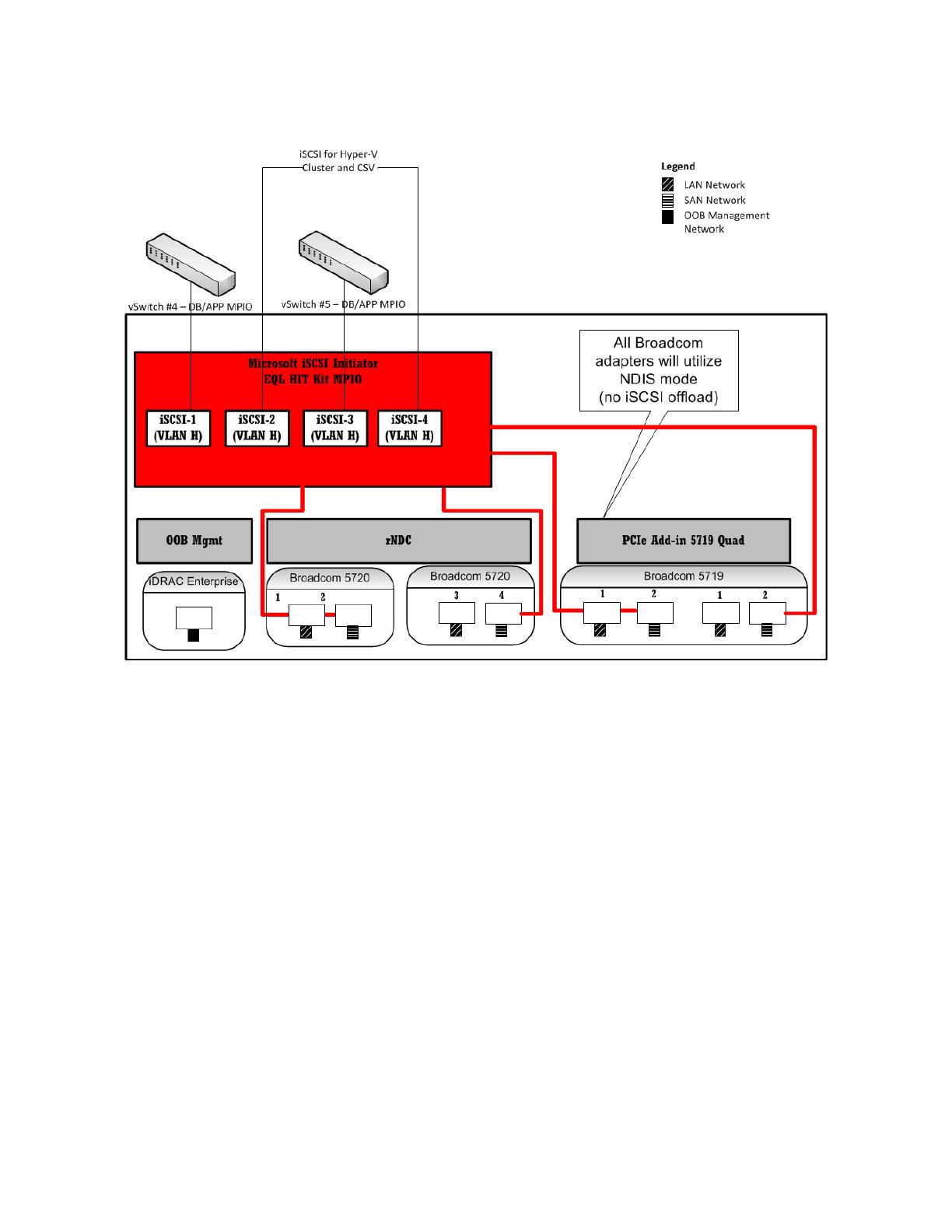
Figure 4 SAN Network architecture - High level overview
In this reference architecture, four physical network connections were allocated for the iSCSI SAN
access on each Hyper-V cluster host. Out of the four available iSCSI connections, two were used by the
Hyper-V cluster for the CSV quorum and CSV volume access. Two virtual switches were created with
the remaining two iSCSI network connections. These iSCSI virtual networks were used by the SQL
Database and SharePoint application servers to access the iSCSI SAN network.
The EqualLogic Host Integration Tool (HIT) kit was installed on the Hyper-V hosts, SQL Database, and
Application servers’ virtual machines and MPIO was used for load balancing the iSCSI traffic and failover.
The same virtual network naming and switches were implemented on all the Hyper-V hosts. This
facilitates successful live migration and easier identification of virtual network elements in the farm.

Implementing SharePoint Server 2010 on Dell vStart Solution - A Reference Architecture for a
SharePoint Server 2010 farm on vStart 100 Hyper-V Solution
17
SharePoint farm configuration
The SharePoint 2010 farm configuration, as shown in Figure 2 above, included two Web Front-End
(WFE), two Application Servers (APP), and two database servers in a failover cluster. The application
servers in the farm were used to host the search query and crawler roles. The farm servers at all tiers
used teamed network connections to provide load balancing and failover capabilities.
Table 5 (below) lists the operating system and software editions used in the farm configurations.
Table 5 OS and software editions
WFE and application servers
Database servers
Operating system
Windows Server 2008 R2 SP1 Data Center Edition
SharePoint server
SharePoint Server 2010 Standard
Edition
NA
Database server
NA
SQL Server 2008 R2 x64 Standard
Edition
NOTE: Step-by-step instructions for installing and configuring a SharePoint farm and any service
applications used in this performance study are outside the scope of this paper. For more information
and resources, refer to the References section of this paper.
The following table shows the configuration of the virtual machines used in this reference architecture.
Table 6 Virtual Machine (VM) configuration
Virtual
machine
Processor
RAM
Storage
Network
WFE and APP
VMs
4 virtual
processors
8GB
OS Fixed VHD
stored on iSCSI
volume
APP: Search
query Index on
iSCSI volume
WFE: 2x virtual
networks for farm
network and NLB
cluster
APP: 1x virtual
networks for farm
network and 2x
virtual network for
in-guest iSCSI
initiators
SQL Server DB
(Failover
Cluster) VMs
4 virtual
processors
16GB
OS Fixed VHD
stored on iSCSI
volume
4 LUNs for SQL
Cluster DB using
in-guest iSCSI
initiators
1x virtual network
for farm network
1x virtual network
for SQL cluster
network
2x virtual network
for in-guest iSCSI
As a part of the farm deployment, EqualLogic HIT Kit was installed in the application and database
virtual machines and the EqualLogic DSM for iSCSI MPIO was enabled. The default Multi-Pathing I/O

Implementing SharePoint Server 2010 on Dell vStart Solution - A Reference Architecture for a
SharePoint Server 2010 farm on vStart 100 Hyper-V Solution
18
(MPIO) policy - ―Least Queue Depth‖ - was used for load balancing the iSCSI traffic from the virtual
machine to the storage arrays.
Configuration of Web Front-End (WFE) servers
This SharePoint 2010 farm design included two WFE servers. The software matrix for these WFE servers
is shown in Table 5. SharePoint 2010 Standard Edition and included only out-of-the-box features used
for collaboration workloads. As a part of the SharePoint collaboration workload, only the standard
search service application was deployed and no other service applications, such as Excel and Visio,
were deployed.
All of the WFE servers were configured in a Network Load Balancing
14
(NLB) cluster. Using NLB,
stateless applications such as SharePoint WFE servers are made scalable by adding additional servers
when the load increases. In this reference architecture, the application server virtual machines were
not a part of the NLB cluster but can be added when additional capacity at the WFE tier is desired.
Redundant network connections were used at the Hyper-V host and also, the virtual switch for NLB
cluster communication was created using this teamed network. Therefore, NLB was configured to use
multicast mode to avoid IP address conflicts
15
in the farm. To access the SharePoint NLB cluster from
different IP subnets, an ARP entry for the NLB cluster name must be added on the LAN switch fabric.
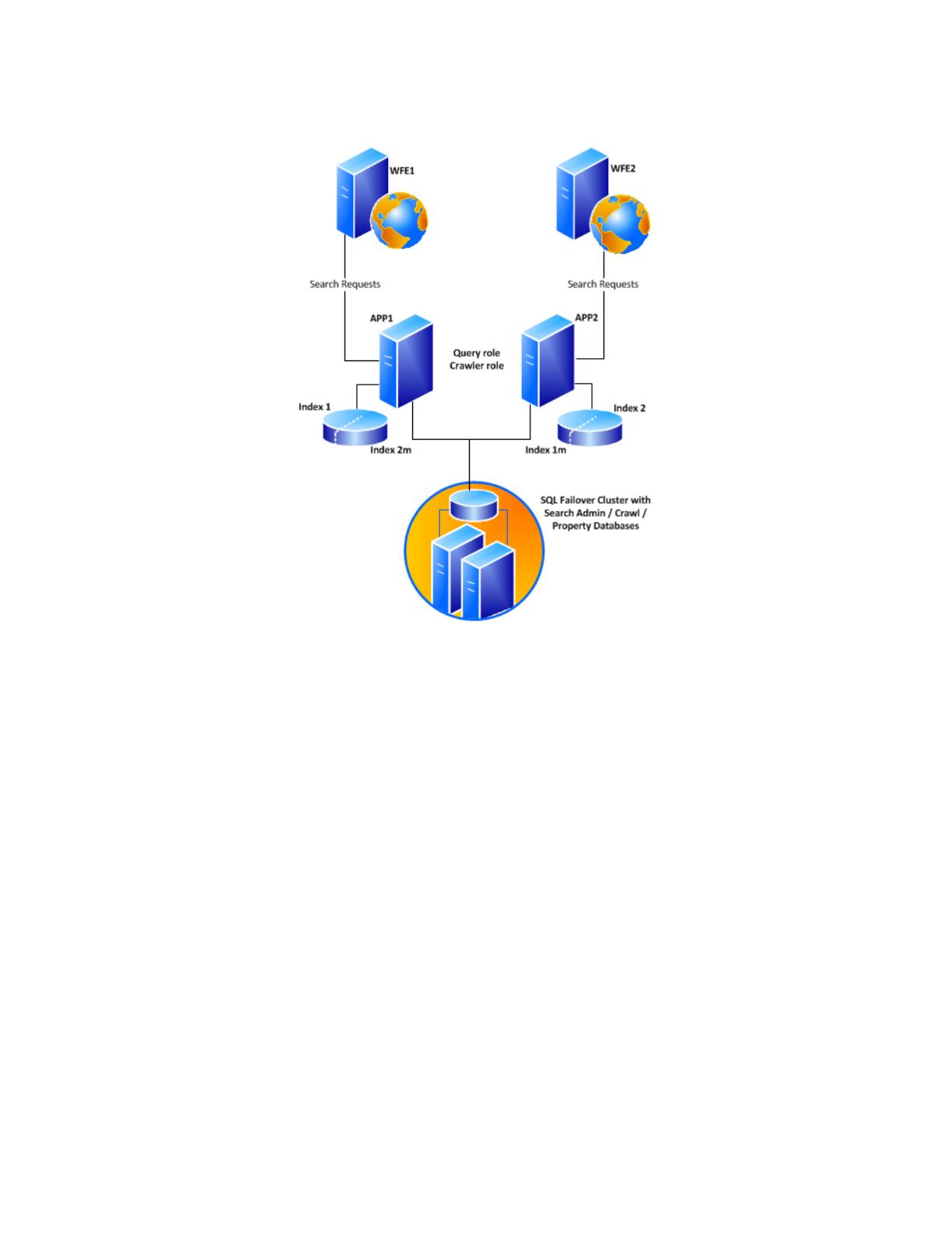
Search service application configuration
SharePoint 2010 changed the search architecture and introduced high availability at the application
tier; for instance, the search crawler. The new search service application architecture in SharePoint
2010 includes greater redundancy. This new design provides flexibility and lets the query and crawler
roles be scaled-out separately on an as-needed basis. Search crawlers are now stateless; they do not
store a copy of the index. However, the index does still propagate and is stored locally on the query
servers. Two virtual machines hosting both crawler and query roles were used in the SharePoint 2010
farm.
The farm configuration used the search service application configuration shown in Figure 5. The search
crawler and query roles were hosted on both of the application servers to enable high availability and
provide improved search performance. Both the crawlers were associated with the same crawl
database, and indexed the same content source.
The search architecture shown in Figure 5 is a logical representation of how the SharePoint Search
service was configured. This configuration provides complete redundancy for both search crawler and
query roles.
14
NLB Deployment Guide: http://technet.microsoft.com/en-us/library/cc732855(WS.10).aspx
15
Using teamed adapters with network load balancing may cause network problems:
http://support.microsoft.com/kb/278431
Implementing SharePoint Server 2010 on Dell vStart Solution - A Reference Architecture for a
SharePoint Server 2010 farm on vStart 100 Hyper-V Solution
19
Figure 5 Search Service Application - architecture
In Figure 5, the index partitions are represented as index 1 and index 2. The two primary index
partitions were mirrored, for redundancy, and a copy (or mirror) of the index partition was placed on
each application server. On both of the application servers, iSCSI initiators in guest OS were used to
connect the storage volumes created on the EqualLogic Storage backend.
Network configuration
As shown in Figure 3, for the WFE servers, two virtual network connections were used. These virtual
network connections were attached to the virtual switches created for farm traffic and NLB cluster
communication. Besides the farm virtual network connections, as shown in Figure 4, the application
servers also used virtual networks associated with the underlying virtual switch connected to the iSCSI
SAN network of the vStart infrastructure. These iSCSI connections within guest OS were used to connect
the application servers to the storage volumes on the EqualLogic arrays and were used to store and
retrieve search query index.
The vStart network architecture design and the segregation of LAN and SAN network helps in isolating
the SharePoint farm traffic from the iSCSI SAN traffic and therefore enhances the overall performance
of the farm.
Configuration of the database server
As shown in Figure 2, the SharePoint 2010 farm—built atop the vStart infrastructure—deployed two
virtual machines as the database servers. Two database servers were deployed in a highly available SQL
failover cluster, with redundant data paths at the database tier of the SharePoint farm. These

Implementing SharePoint Server 2010 on Dell vStart Solution - A Reference Architecture for a
SharePoint Server 2010 farm on vStart 100 Hyper-V Solution
20
database virtual machines were also made a part of the Hyper-V failover cluster to provide physical
host level high availability. This combination ensures faster database failover times using SQL failover
cluster capabilities and provides a second level of high availability using Hyper-V failover clustering.
A SharePoint farm’s performance depends on the performance of the database server and the database
storage backend. In this reference architecture, as the storage resources on the host server hosting the
virtual machine were limited, the SQL instance was connected directly to an external EqualLogic iSCSI
storage array. In this virtualized configuration of the SharePoint farm, one EqualLogic PS6100X storage
array was used to provide sufficient storage capacity and I/O bandwidth to the SQL database contents.
This array provides 24x 600GB 10K RPM SAS drives configured in a RAID 10 for storing the SharePoint
content.
The following table shows how the storage pool was used to host the SharePoint content and other
databases.
Table 7 SharePoint database volumes
Database
LUN size
SharePoint Content Database
2TB
SharePoint Content Logs
200GB
SharePoint Search DB (Crawl,
Admin, and Property)
300GB
WSS Usage Database
500GB
Other SharePoint Databases
(Config and AdminContent)
100GB
Temp Database
200GB
Search Query Index1
200GB
Search Query Index2
200GB
Search Query Mirror1
200GB
Search Query Mirror2
200GB
Memory configuration
By default, SQL Server service uses all available memory
16
because SQL Server dynamically grows and
shrinks the size of the buffer pool depending on the physical memory reported by the operating system.
However, this behavior can be adjusted to limit the amount of physical memory used by SQL Server.
Within the scope of this paper, SQL Server memory was limited to 80 percent of the memory available
in the VM container. For example, on the virtual clustered SQL database server, out of 16GB of memory
in the VM container, 12.8GB was allocated to SQL Server.
Network configuration
Similar to the WFE and application tiers, the database tier also used teamed network connections for
the farm network as shown in Figure 3. For the iSCSI storage network, two virtual network connections
were used for the in-guest iSCSI initiators, and MPIO was configured to provide load balancing and
failover capability.
16
SQL Server memory options - http://msdn.microsoft.com/en-us/library/ms178067.aspx
/