Page is loading ...

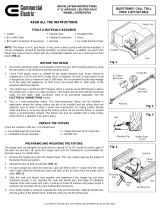
clips of the hanger bars cup underneath the
bottom edges of the joists. Hammer down
the nails of the hanger bars into the
joists to secure the assembly into
place. (FIG. 3 and FIG. 4)
READ ALL THE INSTRUCTIONS
TOOLS & MATERIALS REQUIRED
Before assembling your lighting fixture, refer to the “ELECTRICAL
CONNECTIONS” section. If you feel you do not have electrical wiring
experience, refer to a do-it-yourself wiring handbook or have your fixture
installed by a qualified licensed electrician.
1. To ensure the success of the installation, be sure to read these
instructions and review the diagrams thoroughly before beginning.
2. All electrical connections must be in accordance with local code,
ordinances. If you are unfamiliar with methods of installing electrical
wiring, secure the services of a qualified licensed electrician.
3. Before starting the installation, disconnect electricity at the circuit breaker
or the fuse box. Disconnecting power by using the wall switch is not
sufficient to prevent electrical shock.
4. Check if the power source is suitable for the added electrical load.
Power should be supplied by a 110/120 volt, 60 Hz single circuit. A
standard 120 volt, 15 amp branch circuit is designed to carry a maximum
load of 1800 watts. We recommend that the total wattage of all the lights
and appliances on that circuit, not exceed 80% or 1440 watts, of the
maximum electrical capacity.
5. This product has a SLIDE-N-LOC™ feature, which is used to secure NM
(Romex) cable to the junction box, in lieu of a cable connector. This
feature will not work with BX (armored) cable. For BX cable, cable
connectors need to be purchased separately. See the “ELECTRICAL
CONNECTIONS” section.
6. This is a new-construction fixture. This new-construction fixture can
be installed in applications where the ceiling surface has yet to be
installed and the ceiling joists are exposed, such as when a home is
under new construction. If a ceiling surface already exists and there is
no access above the ceiling surface, do not use this fixture. A remodel
fixture is recommended, instead. This fixture may also be installed onto
a drop ceiling, where there is a standard T-bar grid in place.
7. This fixture is thermally protected. A blinking light indicates an incorrect
lamp type or lamp wattage has been installed, or heat from another
source, such as a heating vent, is affecting the fixture. Always double
check your intended locations prior to installation.
CEILING JOIST INSTALLATION
1. Choose the location for the fixture, taking into consideration the required
7” clearance and the accessibility to the electrical supply.
PREPARING AND MOUNTING THE FIXTURE
UNPACK THE FIXTURE
QUESTIONS? CALL TOLL FREE
1-800-345-0542
INSTALLATION & OPERATION INSTRUCTIONS –
6” NEW CONSTRUCTION IC RECESSED LIGHTING HOUSING WITH SLIDE-N-LOC™ FEATURE
ALL RIGHTS RESERVED. COPYRIGHT © COMMERCIAL ELECTRIC 2010
NOTE: This fixture is an IC type fixture. It may come in direct contact
with thermal insulation. It can be completely covered by thermal
insulation, as shown below. In addition, any part of the fixture may
come in direct contact with any combustible material, such as a ceiling
joist or floor board. (FIG. 1)
NOTE: Insulation
may completely
cover fixture.
FIG. 1
Joist
Fixture
Insulation
FIG. 2
FIG. 3
Bottom edge
of joist
Nail
Mounting Clip
Joist
FIG. 4
Hammer
Hanger bar
Joist
1
st
Crease –
Bend Here
1
st
Notch –
Bend Here
2. Raise the housing/hanger bar assembly to the desired location between
the two ceiling joists. Adjust the width of both hanger bars to the
distance between the joists. Position the assembly so that the mounting
Ladder, BX or NM Cable, BX Cable Connectors (if necessary), Keyhole
Saw, Flathead Screwdriver, Hammer, Insulated Pliers, Pencil, UL Listed
Electrical Tape.
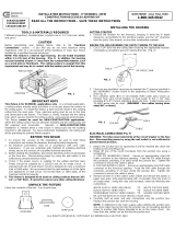
be shortened to accommodate the narrower space. To shorten them:
“Male” Bar
“Female” Bar
Mounting
Clip
Mounting
Clip
MODEL CER105
CAT7ICAT
CAT7ICMA
Housing
Plaster
Frame
Nail
Check the contents of the box. You should have: 1 - Housing/Hanger Bar
Assembly, 1 – Cardboard Circular Template, 3 – “Quick-Connect” Wire
Connectors
HANGER BAR PREPARATION
The hanger bars are designed for joists that are spaced 16” to 26” (center
to center) apart. If the joists are less than 16” apart, the hanger bars must
3. Slide the plaster frame along the hanger bars to the desired position.
Using pliers squeeze the guides of the plaster frame tightly around the
hanger bars to lock the position of the plaster frame.
4. Proceed to the “ELECTRICAL CONNECTIONS” section.
CAUTION
BEFORE YOU BEGIN
4. Slide the “male” and “female” bars together and determine if the hanger
bar has been shortened enough. If not, separate the “male” and
“female” bars and break off additional material at the next crease and
notch. Continue to break off material until proper length is achieved. Do
not break off any more material than necessary.
5. Once proper length is achieved, separate the “male” and “female” bars.
Slide the “female” bars into the guides of the plaster frame. Slide the
“male” bars into the “female” bars.
1. Remove the hanger bars from the plaster frame. This may require
opening the guides of the plaster frame using pliers.
2. Spread the bars as wide as possible. (FIG. 2)
3. For each hanger bar, bend the “male” bar, back and forth at the 1
st
crease from the center until it splits. Bend the “female” bar, back and
forth, at the 1st notch from the center until it splits. (FIG. 2)

T-bar
ALL RIGHTS RESERVED. COPYRIGHT © COMMERCIAL ELECTRIC 2010
Hanger
Bar
DROP CEILING INSTALLATION
1. Choose the location for the fixture, taking into consideration the required
7” clearance and the accessibility to the electrical supply.
2. Install a ceiling tile onto the T-bar grid at the installation location. Using
the provided template and a keyhole saw make a hole at the desired
location in the ceiling tile.
3. Place the housing/hanger bar assembly onto the ceiling tile into the
newly created hole. Adjust the width of both hanger bars to the distance
between the two T-bars, aligning each mounting clip with the top of its
corresponding T-bar. Press down on all mounting clips until they snap
onto the T-bar. (FIG. 5 and FIG. 6) NOTE: Holes are provided on the
mounting clips that can be used to secure the hanger bars to the T-bar.
Parts (I.e. screws, hex nuts) can be
purchased separately for this purpose.
4. Proceed to the “ELECTRICAL
CONNECTIONS” section.
5. Proceed to the “TRIM
INSTALLATION”section.
5. Install the insulation around the housing, if desired. Install the ceiling
material, such as drywall, over the housing. A template is provided to
assist in making the holes in the ceiling material. (NOTE: Blown-in
Insulation may also be installed after the ceiling material has been
installed.)
6. Proceed to the “TRIM INSTALLATION” section.
When using the “quick-connect” wire connectors, be sure that there are
no loose/exposed wire strands. Wrap each wire connection using UL
Listed electrical tape.
Rectangular
Knockout
NM Cable
(ROMEX)
Junction
box door
Flathead
Screwdriver
FIG. 8
“Quick-Connect”
wire connectors
1. Using BX (armored) or NM (Romex) cable, run the supply wiring from the
power supply source to the fixture location. WARNING - Use supply
wires rated 90°C or higher.
2. Open the hinged junction box’s door by lifting the metal latch.
A. FOR BX (ARMORED) CABLE - Break off one of the round knockouts
(FIG. 8) using a screwdriver. Secure an appropriately sized BX cable
connector to the knockout opening. Feed the BX cable through the
connector, providing 6” of slack inside the junction box. Tighten the
connector to secure the cable in place.
B. FOR NM (ROMEX) CABLE – Break off one of the rectangular
knockouts located on the top of the junction box using a screwdriver,
creating a slot. (FIG. 7) Slide the NM cable into the slot, as shown,
making sure there is 6” of slack inside the junction box. (FIG. 8)
3. Remove at least 3” of the cable’s outer sheath and remove the plastic or
paper over-wrap. Strip approximately 3/8” of insulation from the ends of
all supply wires. Using the provided “quick-connect” wire connectors,
make the following wire connections within the junction box:
WHITE Fixture Wire to WHITE (NEUTRAL) Supply Wire
BLACK Fixture Wire to BLACK (HOT) Supply Wire
GREEN Fixture Wire to GREEN / BARE (GROUND) Supply Wire
1. After installing and finishing the ceiling surface, insert the trim into the
housing. Insert the tip of a pencil into the loop of one of the coil springs.
Push the loop upward, stretching the coil spring, inserting the hook into
one of the keyhole slots locate on the socket plate. Repeat with the
remaining coil spring with the remaining keyhole slot to secure the trim in
place. (FIG. 9)
2. Screw a light bulb into the lamp socket and making sure to use the lamp
type an wattage specified on the housing’s lamp replacement label.
3. Installation is complete. Restore electrical power.
FIG. 9
T-bar
Mounting
Clip
FIG. 6
T-bar
Mounting
Clip
FIG. 5
Mounting
Clip
Pry out
knockout
SLIDE-N-LOC™ -
Slide NM cable
into locking slot
4. Close the junction box door until the metal latch snaps, making sure that
all wiring and wire connectors are contained within the box.
FIG. 7
Round
Knockout
Coil Spring
Loop
Hook
Trim
Housing
Keyhole
Slot
NOTE: Additional lighting fixtures may be connected to the fixture’s
junction box. Several knockouts are provided on the junction box to
accommodate additional BX or NM cables intended to connect to other
fixtures. A marking on the junction box door specifies the maximum
number of wires and the maximum wire gauge that can be inserted into
the junction box.
WARNING: First disconnect electricity at the circuit breaker or the fuse
box. Disconnecting power by using the wall switch is not sufficient to
prevent electrical shock.
ELECTRICAL CONNECTIONS
ELECTRICAL CONNECTIONS (CONT.)
TRIM INSTALLATION
COMMERCIAL ELECTRIC
2455 PACES FERRY RD. NW, ATLANTA, GA 30339
/