Page is loading ...

WARNING:
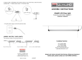
1. The unit is intended to be installed directly beneath a ceiling-mounted
receptacle
2. Do not install on radiant-heating type ceiling.
3. Voltage and current rating of shop light: 120VAC 60Hz.
4. Maximum 8 units to be interconnected.
5. The maximum distance to the receptacle is determined by the 1.5M length
of cord provided.
WARNING: Carefully read and understand the information given in this
manual before beginning the assembly and installation. Failure to do so could
lead to electric shock, fire, or other injuries which could be hazardous or even
fatal.
WARNING: Ensure the electricity to the wires you are working on is shut off.
Either remove the fuse or turn off the circuit breaker.
USE AND CARE GUIDE
LED Directional Shop Light
Installation Instructions
Safety Information
WARNING: This equipment has been tested and found to comply with the
limits for a Class B digital device, pursuant to Part 15 of the FCC Rules.
These limits are designed to provide reasonable protection against harmful
interference in a residential installation. This equipment generates, uses and
can radiate radio frequency energy and, if not installed and used in
accordance with the instructions, may cause harmful interference to radio
communications. However, there is no guarantee that interference will not
occur in a particular installation. If this equipment does cause harmful
interference to radio or television reception, which can be determined by
turning the equipment off and on, the user is encouraged to try to correct the
interference by one or more of the following measures:
■ Reorient or relocate the receiving antenna
■ Increase the separation between the equipment and the receiver.
■ Connect the equipment into an outlet on a circuit different from that to which
the receiver is connected.
■ Consult the dealer or an experienced radio/TV technician for help.
WARNING: Changes or modifications not expressly approved by the party
responsible for compliance could void the user’s authority to operate the
equipment.
WARNING: Added weight of the device may cause instability of a
freestanding portable luminaire. This device is not intended for use with
emergency exits.
Questions, problems, missing parts? Before returning to the store,
call Commercial Electric Customer Service
8 a.m.- 7 p.m., EST, Monday-Friday, 9 a.m. - 6 p.m., EST, Saturday
1-877-527-0313
HOMEDEPOT.COM
Pre-Installation
Installation
Model #2011001402
Warranty
This product is warranted to be free from defects in workmanship and materials
for up to 5 years from date of purchase.
PACKAGE CONTENTS
THANK YOU
enhance your home. Visit us online to see our full line of products available for your home
improvement needs. Thank you for choosing Commercial Electric!
We appreciate the trust and confidence you have placed in Commercial Electric
through the purchase of this LED Directional Shop Light.
We strive to continually create quality products designed to
2. Insert the hanging cable eye hooks (H) into the pilot holes or drywall anchors (E).
If unable to hand tighten, use a screwdriver to assist in securing to the ceiling. See
Fig. 2.
3. Install the hanging cables (F) to the eye hooks. Loosen the two Phillips head screws
on the top of the hanging cables to remove the loop. Feed the loose end of the cable
through the eye hook installed on the ceiling. Reinsert the loose end of the cable
and retighten the two Phillips head screws once the desired length is reached.
Ensure the hanging cable loop is secure. See Fig. 3.
4. While supporting the fixture, install the bottom of the suspension cables into the
keyhole slot in the top of the shop light (A). Do not allow the shop light to hang
unsupported by only one hanging cable during installation. See Fig. 4.
HANGING CABLE INSTALLATION
1. a) Installing to a wooden joist (preferred):
Drill 5/64 in. pilot holes in the ceiling/joists 24-3/4 in. apart. See Fig. 1.
b) Installing to drywall with no wooden joist:
Drill 3/16 in. pilot holes in the ceiling 24-3/4 in. apart. Insert drywall anchors (E)
into pilot holes. See Fig. 1.
A 42 in. Shop Light
B 4.9 ft. Plugin Power Cord/ Linking Cord
C Flush Mounting Screws
D Flush Mounting Rubber Gaskets
E Drywall Anchors
F Hanging Cables
G Pull Chain Extension
H Hanging Cable Eye Hooks
ytitnauQnoitpircseDtraP
1
1
2
2
2
2
1
2
Pre-Installation
PLANNING INSTALLATION
Compare all parts with the Package Contents list in this manual. If any part is missing or
damaged, do not install this product. Contact the Customer Service Team.
TOOLS REQUIRED
Fig. 3
5. Install the pull chain extension (G) if desired. See Fig. 5.
Fig. 5
Fig. 4
6. Install the 5 ft power cord (B) to the fixture and then plug in the other side to a
threeprong electrical outlet. See Fig. 6. If connecting to other Directional Shop Lights,
plug the threeprong plug into the convenience outlet located on the other fixture. See
Fig. 7.
Fig. 6
7. Turn on power at the circuit breaker box and verify the fixture functions properly.
Fig. 7
FLUSH-MOUNT INSTALLATION
1. a) Installing to a wooden joist (preferred):
Drill 5/64 in. pilot holes in the ceiling/joists 26-13.32 in. apart. See Fig. 1.
b) Installing to drywall with no wooden joist:
Drill 3/16 in. pilot holes in the ceiling 26-13.32 in. apart. Insert drywall anchors (E)
into the pilot holes. See Fig. 1.
2. Slide the flush mounting rubber gaskets (D) all the way onto the mounting screws
(C). Insert the mounting screws (C) into the pilot holes in the ceiling with a Phillips head
screw driver until the rubber gaskets (D) compress slightly against the ceiling. Do not
overtighten and squeeze the rubber gaskets (D) as there will not be enough space for
the fixture to slide onto the mounting screws (C). See Fig. 8.
Drywall
Joist
Fig. 8
3. Lift the fixture to the ceiling and align mounting screws with the round opening in
the keyhole slots. Push the fixture onto mounting screws and firmly slide the fixture
until it stops so that the mounting screws seat into the narrow part of the keyhole slots.
When sliding the fixture onto the mounting screws, grip the fixture
with both hands on the ends, do not grip the fixture by the directional
light bars as damage may occur. Ensure that both screws have fully seated
into the keyhole slots and the fixture cannot easily move. If fixture is not secure, slide
fixture off the mounting screws and partially turn the mounting screws further into the
ceiling so that they compress the rubber gaskets slightly. See Fig. 9.
Fig. 9
4. Return to steps 67 of Suspension Cable mounting method to complete electrical
installation.
INSTALLATION OPTIONS
Remove fixture from the carton and check for any shipping damage.
Fig. 2
SPECIFICATIONS
LED Directional Shop Light
Power(W) 42W
Finish Black
4000K
CCT(K)
Lumen(lm)
4000lm
FCC responsible party name: Dangoo Electronics (USA) Co., LTD
Address: 2494 Sand Hill Road
Bldg 7, Suite 100
Menlo Park, CA 94025
United States
Drywall
Joist
TURN OFF POWER AT CIRCUIT BREAKER BOX!
WIRING AND FIXTURE OPERATION CAUTION:
Assistance may be required to support fixture during installation.
WARNING:
Ceiling
5/64 in. Hole
Ceiling
3/16 in. Hole
Drywall
E
Joist
Fig. 1
E
H
H
24 3/4 in.
F
F
1
2
3
G
B
DO NOT connect more than 8 fixtures or a total of 350 watts in a
single run.
NOTE:
D
C
D
C
B
C D E
F
G
H
A
Ceiling
Keyhole slots
Light Distribution
0
30
60
-150
-120
-90
-60
-30
0
400
800
1200
1600
2000
-/+180
150
120
90

ADVERTENCIA:
1. La unidad está diseñada para su instalación debajo de un receptáculo
en el techo.
2. No instalar en un techo con calefacción radiante.
3. Tensión y corriente nominal de la luz de tubo: 120 VCA 60 Hz.
4. Se pueden interconectar hasta un máximo de 8 unidades.
5. La distancia máxima al receptáculo queda determinada por la longitud
de 1.5 m del cable suministrado.
ADVERTENCIA: Lea detenidamente y comprenda la información
proporcionada en este manual antes de comenzar el ensamblaje e
instalación. No hacerlo podría provocar descarga eléctrica, incendio u otras
lesiones que podrían ser peligrosas o fatales.
ADVERTENCIA: Asegúrese de la electricidad que pasa por los cables en los
que está trabajando esté cortada. Quite el fusible o apague el disyuntor
principal.
GUÍA DE USO Y CUIDADO
Luz LED direccional de tubo
Instrucciones de instalación
Información de seguridad
ADVERTENCIA: Los cambios o las modificaciones a esta unidad que no
sean aprobados en forma expresa por la parte responsable del cumplimiento
pueden invalidar el permiso del usuario para operar el equipo.
ADVERTENCIA: El peso adicional del dispositivo puede causar inestabilidad
en una luminaria portátil independiente. Este dispositivo no está diseñado
para su uso en salidas de emergencia.
ADVERTENCIA: Este equipo ha sido probado y encontrado en cumplimiento
con los límites correspondientes a un dispositivo digital de la Clase B,
conforme a la Parte 15 de las Reglas de la FCC. Estos límites están
diseñados para brindar una protección razonable contra la interferencia
dañina en una instalación residencial. Este equipo genera, utiliza y puede
emitir energía de radiofrecuencia y, si no se instala y utiliza de acuerdo
con las instrucciones, puede causar interferencias perjudiciales en las
radiocomunicaciones. Sin embargo, no existe garantía de que no ocurra
interferencia en una instalación en particular. Si este equipo efectivamente
causa interferencia dañina a la recepción de radio o televisión, lo cual puede
determinarse apagando y encendiendo el equipo, se recomienda al usuario
que trate de corregir la interferencia realizando uno o varios de los siguientes
pasos:
■ Cambiar de dirección o de lugar la antena receptora.
■ Aumentar la separación entre el equipo y el receptor.
■ Conectar el equipo en un tomacorriente en un circuito diferente de donde
esté conectado el receptor.
■ Consultar al concesionario o a un técnico de radio/TV con experiencia para
que le ayude.
¿Tiene preguntas o problemas, o le faltan piezas? Antes de devolver a la tienda,
llame al Servicio al Cliente de Commercial Electric
Lunes a viernes de 8:00 a.m. a 7:00 p.m., EST, y los sábados de 9:00 a.m. a 6:00 p.m., EST
1-877-527-0313
HOMEDEPOT.COM
Antes de la instalación
Instalación
Modelo n.º 2011001402
Garantía
Este producto está garantizado contra defectos en la fabricación o las piezas
por un período de 5 años a partir de la fecha de compra.
CONTENIDO DEL PAQUETE
GRACIAS
Visítenos en línea para ver nuestra línea completa de productos disponibles para sus
necesidades de mejoramiento del hogar. ¡Gracias por elegir a Commercial Electric!
Agradecemos la confianza que ha puesto en Commercial Electric con la compra
de esta luz LED direccional de tubo. Nos esforzamos continuamente para crear
productos de calidad diseñados para mejorar su hogar.
2. Inserte los ganchos para cables colgantes (H) en los orificios piloto o en los
anclajes para yeso (E). Si no puede ajustarlos a mano, use un destornillador para
ayudar a fijarlos al techo. Consulte la figura 2.
3. Instale los cables colgantes (F) en los ganchos. Afloje los dos tornillos de cabeza
Phillips en la parte superior de los cables colgantes para desarmar el bucle. Pase el
extremo suelto del cable a través del gancho instalado en el techo. Vuelva a insertar
el extremo suelto del cable y vuelva a ajustar los dos tornillos Phillips una vez que
alcance la longitud deseada. Asegúrese de que el bucle del cable colgante esté firme.
Consulte la figura 3.
4. Con la lámpara sostenida, instale la parte inferior de los cables de suspensión en
la ranura de enganche en la parte superior de la luz de tubo (A). No permita que la luz
de tubo cuelgue sin apoyo de un solo cable durante la instalación. Consulte la figura 4.
INSTALACIÓN DEL CABLE COLGANTE
1. a) Instalación en una viga de madera (preferida):
Taladre orificios piloto de 5/64 pulg. en el techo/viga con una distancia
de 24-3/4 pulg. entre sí. Consulte la figura 1.
b) Instalación en yeso sin viga de madera:
Taladre orificios piloto de 3/16 pulg. en el techo con una distancia de 24-3/4 pulg.
entre sí. Inserte los anclajes para yeso (E) en los orificios piloto. Consulte la
figura 1.
A Luz de tubo de 42 pulg.
B Cable de conexión/Cable de alimentación de 4.9 pies
C Tornillos para montaje a ras
D Juntas de caucho para montaje a ras
E Anclajes para yeso
F Cables colgantes
G Extensión de cadena accionadora
H Ganchos para cables colgantes
CantidadDescripciónPieza
1
1
2
2
2
2
1
2
Antes de la instalación
Distribución de Luz
PLANIFICACIÓN DE LA INSTALACIÓN
Compare todas las partes con la lista de contenido del paquete en este manual. Si falta alguna
parte o está dañada, no instale el producto. Póngase en contacto con el equipo de servicio al cliente.
HERRAMIENTAS REQUERIDAS
Figura 3
5. Instale la extensión de cadena accionadora (G) si así lo desea. Consulte la figura 5.
Figura 5
Figura 4
6. Instale el cable de alimentación de 5 pies (B) a la lámpara y luego enchufe el otro
extremo a un tomacorriente de tres clavijas. Consulte la figura 6. Si se conecta a otra
luz direccional de tubo, conecte el enchufe de tres clavijas en el tomacorriente que se
encuentra en la otra lámpara. Consulte la figura 7.
Figura 6
7. Encienda la alimentación en el disyuntor principal y verifique que la lámpara
funcione correctamente.
Figura 7
INSTALACIÓN A RAS
1. a) Instalación en una viga de madera (preferida):
Taladre orificios piloto de 5/64 pulg. en el techo/viga con una distancia
de 26-13/32 pulg. entre sí. Consulte la figura 1.
b) Instalación en yeso sin viga de madera:
Taladre orificios piloto de 3/16 pulg. en el techo con una distancia
de 26-13/32 pulg. entre sí. Inserte los anclajes para yeso (E) en los orificios piloto.
Consulte la figura 1.
2. Deslice las juntas de caucho de montaje a ras (D) por completo en los tornillos
de montaje (C). Inserte los tornillos de montaje (C) en los orificios piloto en el techo
con un destornillador Phillips hasta que las juntas de caucho (D) queden ligeramente
comprimidas contra el techo. No apriete de más ni comprima las juntas de caucho (D)
ya que no habrá suficiente espacio para que la lámpara se deslice en los tornillos de
montaje (C). Consulte la figura 8.
Yeso
Viga
Figura 8
3. Levante la lámpara hasta el techo y alinee los tornillos de montaje con las
aberturas redondas en las ranuras de enganche. Empuje la lámpara contra los
tornillos de montaje y deslice con firmeza la lámpara hasta que se detenga de modo
que el tornillo de montaje se asiente en la parte estrecha de las ranuras de enganche.
Cuando deslice la lámpara sobre los tornillos de montaje, tome la
lámpara con ambas manos por los extremos, no por los tubos de luz
direccional ya que puede causar daños. Asegúrese de que ambos tornillos
estén bien asentados en las ranuras de enganche y que la lámpara no se pueda
mover con facilidad. Si la lámpara no está firme, deslícela hacia fuera de los tornillos
de montaje y gire parcialmente los tornillos de montaje hacia el techo de modo que
compriman un poco las juntas de caucho. Consulte la figura 9.
Figura 9
4. Regrese a los pasos 6-7 del método de montaje del cable de suspensión para
completar la instalación eléctrica.
OPCIONES DE INSTALACIÓN
Saque la lámpara de la caja y verifique si hubo daños en el transporte.
Figura 2
ESPECIFICACIONES
Luz LED direccional de tubo
Potencia (W) 42 W
Acabado Negro
4000 K
CCT (K)
Lumen (lm)
4000 lm
Nombre de la parte responsable de la FCC: Dangoo Electronics (USA) Co., LTD
Dirección: 2494 Sand Hill Road
Bldg 7, Suite 100
Menlo Park, CA 94025
Estados Unidos
Yeso
Viga
¡APAGUE LA ALIMENTACIÓN EN EL DISYUNTOR
PRINCIPAL!
PRECAUCIÓN SOBRE LA OPERACIÓN DE LA
LÁMPARA Y EL CABLEADO:
Puede que se requiera asistencia para sostener
la lámpara durante la instalación.
ADVERTENCIA:
Techo
Orificio de
5/64 pulg.
Techo
Orificio de 3/16 pulg.
Yeso
E
Viga
Figura 1
E
H
H
24 3/4 pulg.
F
F
1
2
3
G
B
NO conecte más de 8 lámparas o más de 350 vatios en una
misma cadena.
NOTA:
D
C
D
C
B
C D E
F
G
H
A
Techo
Ranuras de
enganche
0
30
60
-150
-120
-90
-60
-30
0
400
800
1200
1600
2000
-/+180
150
120
90
/