Page is loading ...

READ ALL THE INSTRUCTIONS
TOOLS & MATERIALS REQUIRED
QUESTIONS? CALL TOLL FREE
1-800-345-0542
INSTALLATION & OPERATION INSTRUCTIONS –
3” (7,6 mm) IC RECESSED LIGHTING KIT
ALL RIGHTS RESERVED. COPYRIGHT COMMERCIAL ELECTRIC 2013
MODELS: CER3LICR3730
UNPACK THE FIXTURE
Check the contents of the box. You should receive:
• 1 – Housing (can, junction
box)
• 1 - Trim assembly
• 1 – Template
• 3 – Remodel clips (pre-
attached to housing)
• 3 – Wire Nuts
WARNING: First disconnect electricity at the circuit breaker or the fuse box.
Disconnecting power by using the wall switch is not sufficient to prevent
electrical shock.
Choose the location for the fixture(s), keeping in mind the 6” (15,2 cm) depth clearance,
accessibility for the electrical supply, and the ½” (1,3 cm) clearance from the joists, floor
boards, or any other combustible material.
REMODEL INSTALLATION
MAKING THE HOLE/RUNNING THE SUPPLY WIRING TO THE HOLE
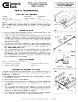
1. Cut a 3 1/4” (8,3 cm) hole into the ceiling after choosing the appropriate location. A
template is provided to assist in making the hole. (Fig. 2)
2. Clear out any insulation necessary to maintain the 3” (7,6 cm) spacing specified in
the “CAUTION” section found in the beginning of these instructions. (See Fig. 1)
3. Run armored cable (BX) or non-metallic (NM) cable (also known as Romex) from
your circuit breaker or fuse panel to the 3 1/4” (8,3 cm) hole, providing 6” (15,2 cm)
to 8” (20,3 cm) of slack extending below the hole. Cable having up to 12 AWG wiring
may be used. (Fig. 3) (WARNING - Use cables having wires rated 90°C or more.)
Hole
Ceiling
Cable
Hole
Fig. 2
Fig. 3
Keyhole saw
BEFORE YOU BEGIN
1. To ensure the success of the installation, be sure to read these instructions and
review the diagrams thoroughly before beginning.
2. All electrical connections must be in accordance with local code and ordinances. If
you are unfamiliar with methods of installing electrical wiring, secure the services of a
qualified licensed electrician.
3. Before starting the installation, disconnect electricity at the circuit breaker or the fuse
box. Disconnecting power by using the wall switch is not sufficient to prevent
electrical shock.
4. Check if the power source is suitable for the added electrical load. Power should be
supplied by a 110/120 volt, 60 Hz single circuit. A standard 120 volt, 15 amp branch
circuit is designed to carry a maximum load of 1800 watts. We recommend that the
total wattage of all the lights and appliances on that circuit, not exceed 80% or 1440
watts, of the maximum electrical capacity.
5. This fixture is designed to be used on ceiling surfaces that are 3/8” (1,0 cm),
1/2” (1,3 cm), or 5/8” (1,6 cm) thick. It cannot be used on any other ceiling
thickness.
Out of the box, this product can be use in REMODEL applications. In a remodel
application, a ceiling surface already exists and there is no access above the surface to
the ceiling joists. To install this fixture, a hole must be made in the existing ceiling from
the room side. Then, electrical wiring must be run to this hole and connected to the
fixture. The fixture is, finally, inserted into the ceiling hole, which secures itself to the
ceiling surface, using special remodel clips (provided). To use this product in NEW-
CONSTRUCTION applications, a Commercial Electric plaster frame and
Commercial Electric hanger bars must be purchased, separately. In a new
construction application, the ceiling surface has not yet been installed and the ceiling
joists are still exposed and accessible.
IMPORTANT NOTE
• Ladder
• BX or NM Cable
• BX or NM Cable
Connectors
• Keyhole Saw or 3 ¼” (8,3
mm) Hole Saw
• Flathead Screwdriver
• Insulated Pliers
• Pencil
• UL Listed Electrical
Tape
4. Proceed to the “ELECTRICAL CONNECTIONS” section.
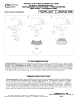
1. Slide the housing through the hole opening. (Fig. 4)
MOUNTING THE HOUSING TO THE CEILING
GETTING STARTED
Fig. 4
Hole
Housing
Ceiling
Remodel
clip
Fig. 1
Insulation
CAUTION
Before assembling your lighting fixture, refer to the “ELECTRICAL CONNECTIONS”
section. If you feel you do not have electrical wiring experience, refer to a do-it-yourself
wiring handbook or have your fixture installed by a qualified licensed electrician.
NOTE: This fixture is an IC type fixture. It may come in direct contact with
thermal insulation. It can be completely covered by thermal insulation, as shown
below. In addition, any part of the fixture may come in direct contact with any
combustible material, such as a ceiling joist or floor board. (FIG. 1)
REV 03-DEC-2013

1. Raise the plaster frame and hanger bar assembly to the desired location between
the two ceiling joists. Adjust the width of both hanger bars to the distance between
the joists. Position the assembly so that the mounting clips of the hanger bars cup
underneath the bottom edges of the joists. Hammer down the nails of the hanger
bars into the joists to secure the assembly into place. (Fig. 8 )
ALL RIGHTS RESERVED. COPYRIGHT COMMERCIAL ELECTRIC 2013
Fig. 5
Remodel
clip
Housing
Foot
2. When the “foot” of each remodel clip touches the ceiling, push the remodel clip
through the “I” shaped opening. (Fig. 5)
3. Continue pushing the clips through, until they snap into position. The “foot” of each
clip will hook the edge of the hole, preventing the housing from sliding further into the
hole. (Fig. 6)
Fig. 6
Remodel
clip
Foot
Housing
NEW CONSTRUCTION INSTALLATION
HANGER BAR PREPARATION
The hanger bars are designed for joists that are spaced 16” (40,6 cm) to 26” (66,0 cm)
(center to center) apart. If the joists are less than 16” (40,6 cm) apart, the hanger bars
must be shortened to accommodate the narrower space. To shorten them:
1. Spread the bars as wide as possible. (Fig. 7)
2. For each hanger bar, bend the “male” bar, back and forth at the 1
st
crease from the
center until it splits. Bend the “female” bar, back and forth, at the 1st notch from the
center until it splits. (Fig. 7)
Fig. 7
1
st
Crease –
Bend Here
1
st
Notch –
Bend Here
“Male” Bar
“Female” Bar
3. Slide the “male” and “female” bars together and determine if the hanger bar has been
shortened enough. If not, separate the “male” and “female” bars and break off
additional material at the next crease and notch. Continue to break off material until
proper length is achieved. Do not break off any more material than necessary.
4. Once proper length is achieved, separate the “male” and “female” bars. Slide the
“female” bars into the guides of the plaster frame. Slide the “male” bars into the
“female” bars.
CEILING JOIST INSTALLATION
2. Slide the plaster frame along the hanger bars to the desired position. Tighten the
locking screw (not shown) of the plaster frame to lock it in place.
3. Run armored cable (BX) or non-metallic (NM) cable (also known as Romex) from
your circuit breaker or fuse panel to the plaster frame hole, providing 6” (15,3 cm) to
8” (20,3 cm) of slack extending below the hole. Cable having up to 12 AWG wiring
may be used. (Fig. 9) (WARNING - Use cables having wires rated 90°C or more.)
4. Detach the remodel clips from the housing.
5. Proceed to the “ELECTRICAL CONNECTIONS” section.
6. Slide the housing through the hole opening, as shown. (Fig. 10 & Fig. 11)
7. Install the ceiling material, such as drywall, over the housing. A template is provided
to assist in making the holes in the ceiling material.
8. Proceed to the “LIGHT BULB AND TRIM INSTALLATION” section.
4. Proceed to the “LIGHT BULB AND TRIM INSTALLATION” section.
Bottom edge
of joist
Fig. 8
Hanger bar
Mounting
Clip
Plaster
Frame
Nail
Fig. 9
BX Cable
Plaster
Frame
Fig. 11
Fig. 10
Housing
Plaster
Frame
REV 03-DEC-2013

1. Plug the FEMALE CONNECTOR of the TRIM onto the MALE CONNECTOR of the
HOUSING.
2. Tuck all wires into the CAN and carefully push the TRIM into CAN.
3. Installation is complete. Restore electrical power.
LIGHT BULB AND TRIM INSTALLATION (Fig. 15)
Fig. 15
TROUBLESHOOTING
Wall switch or circuit breaker is off. Turn on switch or circuit breaker.
Incorrect or loose wire connections Check wire connections
Light bulb may be dead. Test light bulb in
a known working light fixture.
Replace light bulb.
LED driver has malfunctioned. Replace LED driver
Light bulb is loose. Tighten light bulb in socket.
The light is turning off after
being on for some time.
Soon after, it turns back
on. The light continues this
cycle indefinitely.
The thermal sensor turning off due to
excessive heat.
Space away any insulation at least 3"
(7,6 cm) from the housing, as shown in
Fig. 1.
The light does not turn on.
SYMPTOM POSSIBLE CAUSE SOLUTION
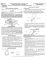
NOTE: In additional to the main supply cable entering the junction box, one more cable
may be fed into the junction box to provide electrical power to another light fixture
intended to be on the same circuit. No more than two cables can be fed into the junction
box. It is very important that the knockout used for the second cable be adjacent to the
knockout used for the first cable. Avoid using a knockout that is on the opposite side of
the first knockout. Using an opposite knockout may make insertion through the ceiling
hole more difficult.
1. Open the junction box’s door by pulling on its metal tab.
2. Break off one of the round knockouts from the junction box using a screwdriver.
Secure an appropriately sized BX or NM (Romex) cable connector to the knockout
opening. Feed the BX or NM (Romex) cable through the connector, providing 3” (7,6
cm) of slack inside the junction box. Tighten the connector to secure the cable in
place.
3. Remove at least 3” (7,6 cm) of the cable’s outer sheath and remove the plastic or
paper over-wrap. Strip approximately 3/8” (1,0 cm) of insulation from the ends of all
supply wires. Using wire nuts, make the following wire connections:
WHITE SUPPLY WIRE (NEUTRAL) TO WHITE FIXTURE WIRE
BLACK SUPPLY WIRE (HOT) TO BLACK FIXTURE WIRE
GREEN/BARE SUPPLY WIRE (GRND) TO GREEN FIXTURE WIRE
ELECTRICAL CONNECTIONS (Fig. 13 & 14)
Be sure that there are no loose strands or loose wires.
4. Wrap all wire connections with electrical tape for a more secure connection. NOTE:
If you have electrical questions, consult your local electrical code for approved
grounding methods.
5. Carefully stuff all wires and wire connections into the junction box. Close the junction
box’s door.
ALL RIGHTS RESERVED. COPYRIGHT COMMERCIAL ELECTRIC 2013
DROP CEILING INSTALLATION
1. Install a ceiling tile onto the T-bar grid at the installation location. Using the provided
template and a keyhole saw make a hole at the desired location in the ceiling tile.
2. Place the plaster frame/hanger bar assembly onto the ceiling tile into the newly created
hole, making sure the bottom of the plaster frame feeds through the hole. Adjust the
width of both hanger bars to the distance between the two T-bars, aligning each
mounting clip with the top of its corresponding T-bar. Press down on all mounting clips
until they snap onto the T-bar. NOTE: Holes are provided on the mounting clips that
can be used to secure the hanger bars to the T-bar. Parts (I.e. screws, hex nuts) can
be purchased separately for this purpose.
NOTE: Drop ceiling installations are similar to new construction installations,
except the hanger bars are attached to the T-bars of a drop ceiling grid, instead of
ceiling joists, as described below.
T-BAR INSTALLATION (Fig. 12)
3. Proceed to Step 3 of the “CEILING JOIST INSTALLATION” section.
Trim
LED
Connection
Housing
T-bar
Ceiling
tile
Hole
Plaster
frame
Hanger
bar
Mounting
clip
Fig. 12
BX Cable
Junction
box door
Wire
nut
Housing
Metal tab
BX Cable
connector
Fig. 13
Fig. 14
Knockout
Housing
REV 03-DEC-2013

ALL RIGHTS RESERVED. COPYRIGHT COMMERCIAL ELECTRIC 2013
DIMMING
Although this product is compatible with most common residential type dimmers,
dimming performance depends on dimmer, dimmer setting (for dimmers with brightness
range adjustments), wiring method, and the number of LED modules. For best results,
set dimmer position at maximum before adjusting to a lower light level.
Recommended Dimmers (minimum load for four LED modules maybe required for
optimal dimming performance): Leviton Decora – 6631, IPI06, Lutron Skylark – S-
603PGH, and Lutron Diva – DVWCL-153PDH, CTCL-15PDH, and TGCL-153PH.
THREE-YEAR LIMITED WARRANTY
Commercial Electric
warrants this product to be free from defects in material and
workmanship for three years from the original date of purchase by the consumer. This
warranty is limited to the counter replacement at the time of purchase, with the original
purchase receipt. Commercial Electric
will not be liable for the loss or damage of any
kind, incidental or consequential damages of any kind, whether based on warranty
contract or negligence, and arising in connection with the sale, use or repair of the
product claimed to be defective. Some states do not allow the exclusion or limitation of
incidental or consequential damages so the above limitation may not apply to you. This
warranty gives you specific legal rights and you may also have other rights, which vary
from state to state. Misuse, accident, improper installation or maintenance will also void
the warranty.
DRIVER REPLACEMENT
1. DISCONNECT MAIN POWER AT FUSE OR CIRCUIT BREAKER.
2. Pull the RETROFIT TRIM down from the RECESSED HOUSING. Unplug the
FEMALE CONNECTOR of the RETROFIT TRIM from the MALE CONNECTOR of
the SOCKET ADAPTER ASSEMBLY.
3. Separate the LED DRIVER CONNECTOR from the RETROFIT TRIM
CONNECTOR.
4. Remove the SCREWS from the BRACKETS holding the LED DRIVER in place and
separate the OLD LED DRIVER from the RETROFIT TRIM.
5. Replace THE OLD LED DRIVER with the NEW LED DRIVER, securing it in place
using the BRACKETS and SCREWS.
6. Connect the LED DRIVER CONNECTOR to the RETROFIT TRIM CONNECTOR.
7. Re-install the RETROFIT TRIM into the RECESSED HOUSING.
Max Case
Temperature 90°C
Dimmable •
tc
LPS Power Supply
AC INPUT:
120 Vac/ 200mA
60 Hz
AC INPUT
L-BLACK
N-WHITE
Made in China
MODEL: RHPS311AL-JW1
UL FILE E185815
DC OUTPUT:
Regulated current 350 mA
Voltage range 12-21V
Maximum power 7.4 W
Maximum voltage 37 V
+ RED
- BLACK
CDL
REV 03-DEC-2013
/