Page is loading ...

METTLER TOLEDO
Seven2Go
Cal
S2
Operating Instructions
Seven2Go™ pH Meter


Table of Contents
Introduction1 5
Safety Measures2 6
Definition of signal warnings and symbols2.1 6
Product specific safety notes2.2 6
Design and Function3 9
Overview3.1 9
Sensor connections3.2 9
T-Pad and hard keys3.3 10
Display and icons3.4 11
Setup menu3.5 13
Navigation3.5.1 13
Menu structure3.5.2 14
Putting into Operation4 15
Scope of delivery4.1 15
Installing the batteries4.2 16
Connecting sensors4.3 17
Installing optional equipment4.4 18
Electrode holder4.4.1 18
Meter base stabilizing unit4.4.2 18
Wrist strap4.4.3 19
Switching the instrument on and off4.5 20
Operation of the Instrument5 21
Calibration5.1 21
Buffer groups5.1.1 21
Define a user-defined buffer standard5.1.2 21
Performing a 1-point calibration5.1.3 21
Performing a 2-point calibration5.1.4 22
Performing a 3-, 4- or 5-point calibration5.1.5 22
Measurement settings5.2 23
Measurement resolution5.2.1 23
Stability criteria5.2.2 23
Endpoint Formats5.2.3 23
Timed Interval Reading5.2.4 24
Rel. mV Offset5.2.5 24
Sample measurement5.3 24
Performing a pH measurement5.3.1 24
Performing a mV or rel. mV measurement5.3.2 24
Temperature measurement5.4 25
Automatic temperature capture (ATC)5.4.1 25
Manual temperature capture (MTC)5.4.2 25
Using the memory5.5 26
Storing a measurement result5.5.1 26
Recalling from memory5.5.2 26
Clearing the memory5.5.3 26
Hot power on/off5.6 27
Instrument self-test5.7 27
Factory reset5.8 27
Table of Contents 3


1Introduction
Thank you for purchasing this high quality METTLER TOLEDO portable meter. Everywhere you measure pH,
conductivity or dissolved oxygen - the Seven2Go™ portables are designed to offer you fast quality data, one-
handed operation and an investment that lasts. Whether you work in the laboratory, at-line or outdoors, the
Seven2Go™ meters will provide you with high quality measurement everywhere you go. The Seven2Go™
offers many exciting features, including:
●
Simple and intuitive menus that shorten steps needed for setting up measurements and calibration
●
T-pad hard keys for comfortable and fast navigation
●
Rubber side-guards for comfortable, one-handed operation
●
IP67 rating for the entire measurement system, including meter, sensor and the connection cables
●
Useful accessories such as the electrode clip, the meter base stabilizing unit, the wrist strap and the uGo™
carrying case with hermetically sealed interior for easy cleaning
5Introduction

2Safety Measures
2.1Definition of signal warnings and symbols
Safety notes are marked with signal words and warning symbols. These show safety issues and warnings.
Ignoring the safety notes may lead to personal injury, damage to the instrument, malfunctions and false results.
Signal words
WARNING for a hazardous situation with medium risk, possibly resulting in severe
injuries or death if not avoided.
CAUTION for a hazardous situation with low risk, resulting in damage to the device or
the property or in loss of data, or minor or medium injuries if not avoided.
Attention (no symbol)
for important information about the product.
Note (no symbol)
for useful information about the product.
Warning symbols
General hazard Toxic substance
Inflammable or explosive substance
2.2Product specific safety notes
Your instrument represents state-of-the-art technology and complies with all recognized safety rules, however,
certain hazards may arise in extraneous circumstances. Do not open the housing of the instrument; it does not
contain any parts that can be maintained, repaired or replaced by the user. If you ever have problems with your
instrument, contact your authorized METTLER TOLEDO dealer or service representative.
Intended use
This instrument is designed for a wide range of applications in various areas and is suitable
for measuring pH (S2, S8), conductivity (S3, S7) or dissolved oxygen (S4, S9).
The use therefore requires knowledge and experience in working with toxic and caustic sub
stances as well as knowledge and experience working with application-specific reagents,
which may be toxic or hazardous.
The manufacturer shall not be held liable for any damage resulting from incorrect usage
divergent to the operating instructions. Furthermore, the manufacturer`s technical specifica
tions and limits must be adhered to at all times and in no way exceeded.
Location
The instrument has been developed for indoor and outdoor operation and may not be used in
explosive environments.
Use the instrument in a location which is suitable for the operation, protected from direct sun
light and corrosive gases. Avoid powerful vibrations, excessive temperature fluctuations and
temperatures below 0°C and above 40°C.
6 Safety Measures

Protective Clothing
It is advisable to wear protective clothing in the laboratory when working with hazardous or toxic substances.
A lab coat should be worn.
Suitable eye protection such as goggles should be worn.
Use appropriate gloves when handling chemicals or hazardous substances, checking their
integrity before use.
Safety notes
WARNING
Chemicals
All relevant safety measures are to be observed when working with chemicals.
a) Set up the instrument in a well-ventilated location.
b) Any spills should be wiped off immediately.
c) When using chemicals and solvents, comply with the instructions of the producer and
the general lab safety rules.
WARNING
Flammable solvents
All relevant safety measures must be observed when working with flammable solvents and
chemicals.
a) Keep all sources of flame away from the workplace.
b) When using chemicals and solvents, comply with the instructions of the producer and
the general lab safety rules.
7Safety Measures

FCC Rules
This device complies with Part 15 of the FCC Rules and Radio Interference Requirements of the Canadian
Department of Communications. Operation is subject to the following conditions: (1) this device may not cause
harmful interference, and (2) this device must accept any interference received, including interference that may
cause undesired operation.
This equipment has been tested and found to comply with the limits for a Class A digital device, pursuant to
Part 15 of the FCC rules. These limits are designed to provide reasonable protection against harmful interfer
ence when the equipment is operated in a commercial environment. This equipment generates, uses, and can
radiate radio frequency energy and, if not installed and used in accordance with the instruction manual, may
cause harmful interference to radio communications. Operation of this equipment in a residential area is likely
to cause harmful interference in which case the user will be required to correct the interference at his own
expense.
8 Safety Measures

3Design and Function
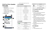
3.1Overview
9
8
11
10
8
1 Status LED (only Pro-series) 7 Rubber feet
2 Display 8 Fixing points for electrode holder
3 Calibration key 9 Micro-USB port (only Pro-series)
4 On/Off key 10 Battery compartment
5 Read key 11 Slot for wrist strap
6 T-Pad
3.2Sensor connections
1 BNC socket for mV/pH sig
nal input
2 RCA (Cinch) socket for tem
perature input
9Design and Function

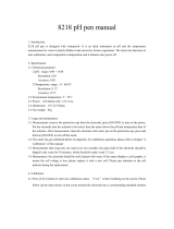
3.3T-Pad and hard keys
Cal
5
3
4
2
1
6
7
Name Function Press
(in measurement
screen)
Press
(other screens)
Read/Take
manual endpoint
•1 Read
Confirm •
Open Setup menu •2
Edit value
(Increase)
•
Save •3
Direction Right •
Switch measurement
mode
•4
Edit value (Decrease) •
Recall last measurement
data
•
Exit •
• > 1 s
(editing mode)
• > 1 s to exit
(calibration mode)
5
Direction Left •
Enter Calibration Mode •6 Cal
Calibration Recall • > 1 s
7 On/Off • 1 s for on
• 3 s for on
• 1 s for on
• 3 s for on
10 Design and Function

3.4Display and icons
When turning on the instrument, the startup screen appears for 3 seconds. The startup screen shows all icons
which can appear on the display. In the following table you find a short description about these icons.
Startup screen
M
Lin
Seg
11Design and Function

Icon Description
1 Buffer/Standard settings
2 --- Offset reading
3
A
Endpoint format
A
Automatic
T
Timed
M
Manual
4 Stability criteria (pH only)
fast
normal
5 --- pH/mV reading
6 ISM sensor has been detected and is properly connected
7 SLOPE Slope is one of two quality indicators for the attached sensor and is determined
during calibration.
Refer to the InLab® sensor's quality certificate for more information.
8 Recall mode
9 Power status
fully charged
half-charged
lowly-charged
fully discharged
10 Measurement mode
11 Hot power on
(Instrument never shuts down automatically until power is used up or the
On/Off button is pressed manually)
12
Int.
Timed interval reading mode active
13 Calibration mode
Indicates calibration mode and appears whenever you are performing a cali
bration or reviewing calibration data.
14 Error occured
15 Setup mode
16
Self-Diag.
Self-diagnosis mode
Self-Diag.
Self-diagnosis indicator
Indication to press key
Self-diagnosis passed
17 Electrode performance
Slope: 95-105% / Offset: ± 0-15mV (Electrode in good condition)
Slope: 90-94% / Offset: ± 15-35mV (Electrode needs cleaning)
Slope: 85-89% / Offset: > 35mV (Electrode is faulty)
18 --- Calibration point / Error messages
19 --- Main Menu structure
12 Design and Function

3.5Setup menu
3.5.1Navigation
For general navigation in the setup menu read the following information:
●
Press to enter the setup menu.
●
Press and hold to exit the setup menu.
●
Press Read to confirm a change.
●
Press and hold Read to exit the setup menu and return directly to the measurement screen from every posi
tion in the setup menu.
1 --- Read
●
Read / save cal data
●
Confirm entered values
2 Setup / Up
●
Enter the setup menu.
●
Move up in the menu structure.
●
Edit value (increase).
3 Save / Right
●
Save measurement data.
●
Store last calibration point to end calibration.
●
Go right.
4 Mode / Down
●
Change measurement mode.
●
Move down in the menu structure.
●
Edit value (decrease).
Cal
5
3
4
2
1
5 Recall / Left
●
Recall data / recall the last step.
●
Go left.
●
For menu or data memory exit
(press >1s).
13Design and Function

3.5.2Menu structure
General Settings
1. Temperature Settings
1.2 Cal 1
1.3 Cal 2
2. Stability Criterion
2.1 Fast
2.2 Normal
3. Endpoint Formats
3.1 Automatic
3.2 Timed
3.2.1 Measurement Time
1.
3.3 Manual
Measurement Settings
1. Interval Time
2. Resolution
2.
3. Rel.mV
Calibration Settings
1. Set Buffer Group
1.1 Buffer 1
1.1.1 Linear | Segmented
1.2 Buffer 2
1.2.1 Linear | Segmented
1.3 Buffer 3
1.3.1 Linear | Segmented
1.4 Buffer 4
1.4.1 Linear | Segmented
1.5 Buffer 5
3.
1.5.1 Linear | Segmented
14 Design and Function

4Putting into Operation
4.1Scope of delivery
Check the completeness of the delivery. The following accessories are part of the standard equipment of your
new instrument:
METTLER TOLEDO
Cal
S2 instrument
for pH/mV measurement
Battery LR3/AA 1.5V
4pcs.
Electrode holder
Seven2Go
Operating Instructions
Test Report
many more
CD-ROM including operating instructions
15Putting into Operation

4.2Installing the batteries
1
2
1.
2.
4 x LR3/AA 1.5V
or 4 x HR6/AA 1.2V
3
4
5
6
16 Putting into Operation

4.3Connecting sensors
ISM
®
sensor
When connecting an ISM
®
sensor to the meter, one of the following conditions has to be met for the calibration
data to be transferred automatically from the chip of the sensor into the meter and usage for further measure
ments. After attaching the ISM
®
sensor the following steps must be followed:
●
Switch on the meter.
●
Press Read key or press Cal key.
The icon appears on the display. The sensor ID of the sensor chip is registered and appears on the display.
The calibration history and the sensor-data can be reviewed in the data menu.
Note
●
We strongly recommend to switch off the meter when disconnecting an ISM sensor! In doing so, you make
sure that the sensor is not removed while the instrument is reading data from or writing data to the ISM-chip
of the sensor.
17Putting into Operation

4.4Installing optional equipment
4.4.1Electrode holder
For a safe placing of the electrode you can mount an electrode holder on the side of the instrument. The
elctrode holder is part of delivery. You can mount it on either sides of the instrument for your personal handling.
1 Remove the protective clips (1).
1
2 Push the electrode holder (1) into the recess (2) of the
instrument.
1
2
4.4.2Meter base stabilizing unit
The meter base stabilizing unit should be mounted when using the instrument on a desk. It ensures a more firm
and secure stand when pressing the keys.
1 Remove the protective clips (1).
1
2 Push the meter base stabilizing unit (1) into the recess
es (2) of the instrument.
1
2
18 Putting into Operation

4.4.3Wrist strap
For better protection against damage caused by dropping, you can mount the wrist strap as shown in the fol
lowing diagrams.
M
E
T
T
L
E
R
T
O
L
E
D
O
M
E
T
T
L
E
R
T
O
L
E
D
O
O
L
E
D
O
1
2
O
L
E
D
O
M
E
T
T
L
E
R
T
O
L
E
D
O
M
E
T
T
L
E
R
T
O
L
E
D
O
M
E
T
T
L
E
R
E
T
T
L
E
R
M
E
T
T
L
E
R
T
O
L
E
D
O
M
E
T
T
L
E
R
T
O
L
E
D
O
O
L
E
D
O
3
M
E
T
T
L
E
R
T
O
L
E
D
O
M
E
T
T
L
E
R
M
E
T
T
L
E
R
T
O
L
4
19Putting into Operation

4.5Switching the instrument on and off
1 Press and release to switch on the instrument.
All segmented digital numbers and icons are dis
played for 2 seconds. After that the installed soft
ware version appears (e.g. 1.00) and the instru
ment is ready for use.
2 Press for 2seconds and release to switch off the
instrument.
EDO
Cal
Note
●
By default after 10 minutes not in use, the instrument shuts down automatically. The auto-off function can
be turned on/off in the setup menu, under General settings.
See also
●
Hot power on/off (page27)
20 Putting into Operation
/