
USER MANUAL
BCM91125F
91125F-UM100-R
16215 Alton Parkway • P.O. Box 57013 • Irvine, CA 92619-7013 • Phone: 949-450-8700 •Fax: 949-450-8710 02/18/04
Evaluation Board

Broadcom Corporation
P.O. Box 57013
16215 Alton Parkway
Irvine, CA 92619-7013
© 2004 by Broadcom Corporation
All rights reserved
Printed in the U.S.A.
Broadcom
®
and the pulse logo are registered trademarks of Broadcom Corporation and/or its subsidiaries in the United
States and certain other countries. All other trademarks mentioned are the property of their respective owners.
REVISION HISTORY
Revision Date Change Description
91125F-UM100-R 02/18/04 Initial release.

User Manual BCM91125F
02/18/04
Broadcom Corporation
Document 91125F-UM100-R Page iii
TABLE OF CONTENTS
Section 1: Product Overview ..............................................................................................1
Introduction .................................................................................................................................................. 1
Items Included with the Shipment .............................................................................................................. 1
Features ........................................................................................................................................................ 1
Hardware ................................................................................................................................................ 1
Firmware ................................................................................................................................................. 2
Section 2: Getting Started...................................................................................................3
Section 3: Physical Description .........................................................................................4
Block Diagram .............................................................................................................................................. 4
Connectors ................................................................................................................................................... 5
Powering Up the Board ............................................................................................................................... 6
LEDs .............................................................................................................................................................. 6
Fuse and Battery .......................................................................................................................................... 8
Switches........................................................................................................................................................ 9
BCM1125H Peripheral Devices ................................................................................................................. 10
Section 4: Firmware Configuration ..................................................................................11
Section 5: Troubleshooting ..............................................................................................12
Corrective Procedures............................................................................................................................... 12
Replacement Parts ..................................................................................................................................... 12
Section 6: Web Resources................................................................................................13
SiByte .......................................................................................................................................................... 13
Peripherals.................................................................................................................................................. 13
Bus Interface .............................................................................................................................................. 13

BCM91125F User Manual
02/18/04
Broadcom Corporation
Page iv Document 91125F-UM100-R

User Manual BCM91125F
02/18/04
Broadcom Corporation
Document 91125F-UM100-R Page v
LIST OF FIGURES
Figure 1: Top View ............................................................................................................................................. 4
Figure 2: Block Diagram ..................................................................................................................................... 4
Figure 3: Connector Callouts.............................................................................................................................. 5
Figure 4: LED Callouts ....................................................................................................................................... 6
Figure 5: Fuse and Battery Callouts ................................................................................................................... 8
Figure 6: Switch Callouts.................................................................................................................................... 9

User Manual BCM91125F
02/18/04
Broadcom Corporation
Document 91125F-UM100-R Page vi
LIST OF TABLES
Table 1: Connector Descriptions ........................................................................................................................ 5
Table 2: LED Descriptions.................................................................................................................................. 7
Table 3: Fuse and Battery Descriptions ............................................................................................................. 8
Table 4: Switch Descriptions .............................................................................................................................. 9
Table 5: SMBus Peripherals............................................................................................................................. 10
Table 6: Generic Bus Peripherals..................................................................................................................... 10
Table 7: GPIO Map........................................................................................................................................... 10
Table 8: PCI Interrupt Map ............................................................................................................................... 10
Table 9: Firmware Generic Bus Memory Mapping ........................................................................................... 11
Table 10: Firmware Configuration Bits Mapping .............................................................................................. 11
Table 11: Replacement Parts ........................................................................................................................... 12
Table 12: SiByte Web Resources..................................................................................................................... 13
Table 13: Peripheral Web Resources............................................................................................................... 13
Table 14: Bus Interface Web Resources.......................................................................................................... 13

User Manual BCM91125F
02/18/04
Broadcom Corporation
Document 91125F-UM100-R Product Overview Page 1
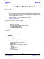
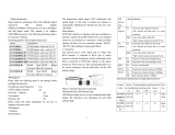
Section 1: Product Overview
INTRODUCTION
The BCM91125F evaluation board is an evaluation platform intended to support the needs of prospective
users of the BCM1125H processor. This user manual provides information on how to get the BCM91125F
evaluation board up and running quickly. This manual also describes how to locate, configure, and observe
the various connectors, switches, jumpers, and LEDs on the BCM91125F, allowing software development and
evaluation of the BCM1125H processor to begin.
For additional information on this board and the BCM1125H processor, go to:
http://sibyte.broadcom.com/public.
ITEMS INCLUDED WITH THE SHIPMENT
The following items are included with the BCM91125F evaluation board shipment:
• BCM91125F evaluation board
• OCDemon Macraigor Systems Wiggler parallel port JTAG probe
• 120–240V AC to 5V DC power adapter
• Viosoft ARRIBA
®
Embedded Edition CD
• This document
FEATURES
This section describes the BCM91125F’s features.
HARDWARE
• BCM1125H processor
• Half-length PCI card form factor
• 128 MB of DDR SDRAM
• Two 10/100/1000 Mbps Ethernet interfaces with RJ45 connectors
• One UART with RS232 interface
• Universal 32-bit, 33/66-MHz capable PCI connector
• 16-MB Flash ROM
• Two SMBus channels with the following devices connected:
-RTC
- EEPROMs
- temperature sensor
• EJTAG connector
• Four-character LED display

BCM91125F User Manual
02/18/04
Broadcom Corporation
Page 2 Features Document 91125F-UM100-R
FIRMWARE
The Common Firmware Environment (CFE) is designed to be easily portable to designs incorporating current
and future Broadcom MIPS64-compatible broadband processors. Supported platforms include Broadcom’s
SiByte processor family (BCM1250, BCM1125H, and so forth), 32-bit and 64-bit memory models, and big and
little-endian operation. There are many parameters configurable at build time that can be used to customize
CFE to suit diverse customer requirements.
On the BCM91125F, CFE can load programs (such as S-records, raw binary, or ELF formatted) from bootstrap
devices in a variety of ways, including:
• Via either Ethernet port, from a TFTP server
• Via the serial port (S-records only)
For additional information on CFE, refer to the
Common Firmware Environment (CFE) Specification
document
that can be found in the CFE source code distribution at: http://sibyte.broadcom.com/public.

User Manual BCM91125F
02/18/04
Broadcom Corporation
Document 91125F-UM100-R Getting Started Page 3
Section 2: Getting Started
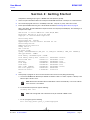
Complete the following steps to get to a BCM91125F CFE (firmware) prompt.
1 Connect a 9-pin null modem cable to the serial port of the BCM91125F and to a serial port on a workstation/PC.
2 Use a terminal program and set it to 115200 bps, 8-bit data, 1-stop bit, no parity, and no flow control.
3 Power up the BCM91125F using one of the methods described in “Powering Up the Board” on page 6.
After a short delay, the CFE initialization output and serial console prompt should display. The following is an
example of the output:
CFE version 1.0.40 for BCM91125F (64bit,MP,BE,MIPS)
Build Date: Wed Jan 14 15:07:22 PST 2004
Copyright (C) 2004 Broadcom Corporation.
Initializing Arena.
Initializing PCI. [normal]
HyperTransport not initialized: InitDone not set
Initializing Devices.
BCM91125F board revision 0
Config switch: 2
CPU: 1125H A2
L2 Cache: 256KB
SysCfg: 0080000008C20600 [PLL_DIV: 12, IOB0_DIV: CPUCLK/4, IOB1_DIV: CPUCLK/3]
CPU type 0x40103: 600MHz
Total memory: 0x8000000 bytes (128MB)
Total memory used by CFE: 0x87E96360 - 0x88000000 (1481888)
Initialized Data: 0x87E96360 - 0x87E9FE80 (39712)
BSS Area: 0x87E9FE80 - 0x87EA05A0 (1824)
Local Heap: 0x87EA05A0 - 0x87FA05A0 (1048576)
Stack Area: 0x87FA05A0 - 0x87FA25A0 (8192)
Text (code) segment: 0x87FA25A0 - 0x87FFFFB4 (383508)
Boot area (physical): 0x07E55000 - 0x07E95000
Relocation Factor: I:E83A25A0 - D:05F96360
CFE>
4 At the prompt, a program can be run via the network from a TFTP server by doing the following:
a. Connect the BCM91125F Ethernet port E0 with an Ethernet cable to a switch, repeater, or directly to the
Ethernet port of the file server.
b. To initialize Ethernet port E0, type the following:
ifconfig eth0 -auto
c. To run a program, type the following:
boot -elf tftp_server:/path_to_software/program
Note: Because the Broadcom PHYs handle direct connects automatically, a crossover cable for
direct connects is not needed.
Note: The ifconfig eth0 -auto command can only be used with a DHCP server.

BCM91125F User Manual
02/18/04
Broadcom Corporation
Page 4 Physical Description Document 91125F-UM100-R
Section 3: Physical Description
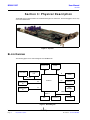
The BCM91125F is implemented in the standard half-length PCI card format. The following figure shows a top
view of the BCM91125F.
Figure 1: Top View
BLOCK DIAGRAM
The following figure shows a block diagram of the BCM91125F.
Figure 2: Block Diagram
Serial Port 0
EJTAG
DRAM
Flash ROM
Four-character
LED
BCM1125
JTAGS0
M
IO_AD
PCI
Connector
PCI
E0
10/100/1000
Ethernet Port
E0
SPD
EEPROM
SMBus 0
E1
10/100/1000
Ethernet Port
E1
EEPROM
RTC
Temp Sensor
SMBus 1

User Manual BCM91125F
02/18/04
Broadcom Corporation
Document 91125F-UM100-R Connectors Page 5
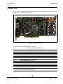
CONNECTORS
Figure 3 shows the board and identifies connectors numerically. For a description of each connector callout,
compare Figure 3’s number callouts with Table 1.
Figure 3: Connector Callouts
The following table shows the BCM91125F connectors.
Table 1:
Connector Descriptions
Board ID Description
J2 *** Dual-sided 62-pin edge finger PCI connector.
J8 Serial port 0 RS-232 connector.
J14 DEBUG_L trigger for scope (pin1 * = GND, pin2 = DEBUG_L).
J15 EJTAG connector.
J18 1.2V core supply sense (pin1 ** = GND, pin2 = 1.2V).
J19 *** Standard hard drive power supply connector.
J23A 10/100/1000 Mbps Ethernet Port E1.
J21 2.5V supply sense (pin1 ** = GND, pin2 = 2.5V).
J22 3.3V supply sense (pin1 ** = GND, pin2 = 3.3V).
J23B 10/100/1000 Mbps Ethernet Port E0.
J24 *** 5V power supply jack.
* = Pin1 located by viewing the back side of the board for the square solder point.
** = Pin1 located by viewing the front of the board for the square solder pad.
*** = Important: Use only one of the three available power supplies.

BCM91125F User Manual
02/18/04
Broadcom Corporation
Page 6 Powering Up the Board Document 91125F-UM100-R
POWERING UP THE BOARD
Any
one
of the following three methods supply power to the board by plugging in:
• The BCM91125F board’s PCI connector (J2) to a PCI slot on a motherboard.
• A HDD power cable from a standard PC power supply to the HDD connector (J19).
• The supplied 120–240V AC to 5V DC adapter to the 5V DC connector (J24).
Only
one
of these methods should be employed at any given time.
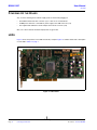
LEDS
Figure 4 shows the positions of the LEDs numerically. Compare Figure 4’s number callouts with a description
of each LED in Table 2 on page 7.
Figure 4: LED Callouts

User Manual BCM91125F
02/18/04
Broadcom Corporation
Document 91125F-UM100-R LEDs Page 7
Table 2:
LED Descriptions
Board ID Color Description
D3 Amber System reset.
D4 Amber Cold reset.
D7 * Ethernet Port E1 PHY LEDs
Red Link2 = Speed indicator.
Green Link1 = Speed indicator.
Yellow Fdx = Full-duplex indicator.
Green Slv = Slave indicator.
Yellow Act = Transmit and receive activity indicator.
Green Link = Link quality indicator.
D12 * Ethernet Port E0 PHY LEDs
Red Link2 = Speed indicator.
Green Link1 = Speed indicator.
Yellow Fdx = Full-duplex indicator.
Green Slv = Slave indicator.
Yellow Act = Transmit and receive activity indicator.
Green Link = Link quality indicator.
D13 Green Debug LED.
D16 Green 3.3V power good.
D18 Green 5V.
* = LEDs visible from the board’s side panel.

BCM91125F User Manual
02/18/04
Broadcom Corporation
Page 8 Fuse and Battery Document 91125F-UM100-R
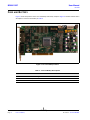
FUSE AND BATTERY
Figure 5 shows the positions of the fuse and battery numerically. Compare Figure 5’s number callouts with a
description of each fuse and battery in Table 3.
Figure 5: Fuse and Battery Callouts
Table 3:
Fuse and Battery Descriptions
Board ID Function
F3 * EJTAG current limiting fuse
BT1 RTC battery
* = Fuse located on the back side of the board.

User Manual BCM91125F
02/18/04
Broadcom Corporation
Document 91125F-UM100-R Switches Page 9
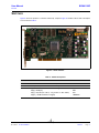
SWITCHES
Figure 6 shows the positions of switches numerically. Compare Figure 6’s number callouts with a description
of each switch in Table 4.
Figure 6: Switch Callouts
Table 4:
Switch Descriptions
Board ID Function Default
SW2 Cold reset asserted when the button is pressed NA
SW3 NMI (GPIO 8) asserted when the button is pressed NA
SW4 8-position DIP switch, used for board configuration 0b01000010
dip[8] = GPIO[15] 0b0
dip[7] = System byte order (1 = big endian; 0 = little endian) 0b1
dip[6:1] = BCM1125H SW config[5:0] 0b000010

BCM91125F User Manual
02/18/04
Broadcom Corporation
Page 10 BCM1125H Peripheral Devices Document 91125F-UM100-R
BCM1125H PERIPHERAL DEVICES
Table 5:
SMBus Peripherals
SMBus Channel SMBus Address Description
0 0x2A Maxim MAX6654 temperature sensor.
0 0x50 Microchip 28LC128C EEPROM.
00x54
Atmel
®
AT24C02 SPD EEPROM*.
1 0x68 ST Microelectronic M41T81 RTC.
* = Overwriting the data on the SPD EEPROM could adversely affect the firmware’s ability to configure the DRAM correctly.
Table 6:
Generic Bus Peripherals
Chip Select # Description
CS0
Intel
®
E28F128J3A boot ROM.
CS6 HP HDLO-2416 LED display.
Table 7:
GPIO Map
GPIO Pin # BCM1125H Pin Direction Description
0 Output DEBUG_LED (LED D13).
1 Input OUT from RTC.
7 Input PHY_INT_L (ORed PHY interrupt from both BCM5421
PHY chips).
8 Input NMI_L from switch SW3.
9 Input TEMP_ALERT_L from the temperature sensor.
15 Input Undefined SW config from the switch (SW4 dip[8]).
Table 8:
PCI Interrupt Map
Description Interrupt Map
32-bit universal PCI connector. BCM1125H PCI INTA = PCI Connector (J2) INTA

User Manual BCM91125F
02/18/04
Broadcom Corporation
Document 91125F-UM100-R Firmware Configuration Page 11
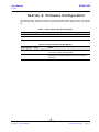
Section 4: Firmware Configuration
The firmware image in the flash is bi-endian, so it supports both big and little-endian operation. The following
table describes where and how much physical memory the firmware maps to the chip selects on the generic
bus.
Table 9:
Firmware Generic Bus Memory Mapping
Chip Select Description Physical Memory Address Size
CS0 Boot ROM 0x1FC0_0000 16 MB
CS6 LED Display 0x1D0A_0000 64 KB
Table 10:
Firmware Configuration Bits Mapping
SW Config Bit # Name Action
0 autostartup CFE attempts to execute the value stored in the STARTUP
environment variable after initialization.
1 config PCI CFE configures PCI for device mode operation during
initialization. This switch should be set for use in a host PC/
workstation.

BCM91125F User Manual
02/18/04
Broadcom Corporation
Page 12 Troubleshooting Document 91125F-UM100-R
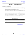
Section 5: Troubleshooting
CORRECTIVE PROCEDURES
1 When CFE is not able to initialize the system and reach the console prompt, the four-character alphanumeric
LED display may be used to help debug the initialization sequence. When the Cer2 message appears, a cache
error has occurred. This frequently occurs when the BCM1125H is either undercooled or is in a low-voltage
situation. Ensure that the correct voltage and cooling is being provided. For other LED message descriptions,
refer to the
Common Firmware Environment (CFE) Specification
document.
2 There is no output coming from the serial boot console, but the four-character LED displays
CFE
. Because
CFE uses serial port 0 by default, ensure that a standard 9-pin RS232 null-modem cable connection is being
used. Also ensure that the terminal program is set to a baud rate of 115200, 8-bit, no parity, no flow control.
3 PCI problems may be encountered when placing the BCM91125F board into a PCI slot on a host PC or
workstation. The BCM91125F is hardwired in PCI device mode. Problems may occur if the BCM91125F is
reset, which clears the host-configured PCI registers in the BCM1125H without the host’s knowledge.
If this problem occurs and the PCI interface is being used only for the purpose of powering the BCM91125F,
remove the board from the PCI slot and choose one of the other methods for powering the board. If the host
system needs to be connected to the BCM91125F through the PCI, then the system must reconfigure the
BCM1125H registers after the BCM91125F is reset, which may include rebooting the host system.
REPLACEMENT PARTS
Table 11:
Replacement Parts
Board
ID
Description Manufacturer Manufacturer ID Web Information
F3 EJTAG connector 0.5A
32V surface mounted
fuse.
Littelfuse
®
434.500 http://www.littelfuse.com/PDFs/
Products/434.pdf
N/A 110–240V~1.6A AC to
5V 6A DC power
supply.
Globtek
®
, Inc.
GT-21097-3005 http://www.globtek.com/datasheets/
pdf/GT(M)21097.pdf
BT1 RTC battery. Panasonic BR1225/1HC http://www.panasonic.com/industrial/
battery/oem/chem/lith/coin1.htm

User Manual BCM91125F
02/18/04
Broadcom Corporation
Document 91125F-UM100-R Web Resources Page 13
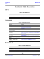
Section 6: Web Resources
SIBYTE
PERIPHERALS
BUS INTERFACE
Table 12:
SiByte Web Resources
Resource Website
BCM1250 and BCM1125H User Manual http://sibyte.broadcom.com/public/resources/
SB1 Core User Manual http://sibyte.broadcom.com/public/resources/
General information http://sibyte.broadcom.com/public/
Table 13:
Peripheral Web Resources
Resource Website
Maxim MAX6654 temperature sensor http://pdfserv.maxim-ic.com/en/ds/MAX6654.pdf
Microchip 24LC128C serial EEPROM http://www.microchip.com/1010/pline/memory/memdvice/ic/
64to512/devices/24lc128/index.htm
ST Microelectronic M41T81serial RTC http://www.st.com/stonline/products/families/memories/rtc/
nv_t81.htm
HP HDLO-2416 four-character
alphanumeric display
http://literature.agilent.com/litweb/pdf/5988-3269EN.pdf
Atmel AT24C02 serial EEPROM (SPD
for memory)
http://www.atmel.com/dyn/products/
product_card.asp?family_id=647&family_name=Serial+EEPRO
M&part_id=2805
Samsung K4H561638D-TCA2 256Mb
DDR SDRAM
http://www.samsung.com/Products/Semiconductor/DRAM/
DDRSDRAM/DDRSDRAMcomponent/256Mbit/K4H561638D/
K4H561638D.htm
Intel E28F128J3A 128 Mbit Strataflash
®
Memory
http://www.intel.com/design/flcomp/datashts/290667.htm
Broadcom BCM5421 10/100/
1000BASE-T Gigabit Copper
Transceiver
http://www.broadcom.com/products/
product.php?product_id=BCM5421&cookiecheck=1
Table 14:
Bus Interface Web Resources
Resource Website
EJTAG
specification
http://www.mips.com/content/Documentation/MIPSDocumentation/EJTAG/doclibrary/
PCI specification http://www.pcisig.com/specifications/conventional/

Document 91125F-UM100-R
Broadcom Corporation
16215 Alton Parkway
P.O. Box 57013
Irvine, CA 92619-7013
Phone: 949-450-8700
Fax: 949-450-8710
Broadcom Corporation reserves the right to make changes without further notice to any products or data herein to improve reliability, function, or design.
Information furnished by Broadcom Corporation is believed to be accurate and reliable. However, Broadcom Corporation
does not assume any liability arising out of the application or use of this information, nor the application or use of any product or
circuit described herein, neither does it convey any license under its patent rights nor the rights of others.
BCM91125F User Manual
02/18/04
-
 1
1
-
 2
2
-
 3
3
-
 4
4
-
 5
5
-
 6
6
-
 7
7
-
 8
8
-
 9
9
-
 10
10
-
 11
11
-
 12
12
-
 13
13
-
 14
14
-
 15
15
-
 16
16
-
 17
17
-
 18
18
-
 19
19
-
 20
20


Broadcom 91125F-UM100-R.pdf User manual
- Type
- User manual
- This manual is also suitable for
Ask a question and I''ll find the answer in the document
Finding information in a document is now easier with AI
Related papers
-
LSI BCM91125E User manual
-
Broadcom BCM91125PCIX User manual
-
-
-
-
-
-
-
-
Other documents
-
Clatronic BSS 7013 User manual
-
Solar CFE-5100S User manual
-
Panasonic CZ-CFUNC1U Installation guide
-
CFE S Pro Series User manual
-
Measurement Computing USB-2416 User manual
-
 Mips Technologies Malta User manual
-
Intel IQ80333 User manual
-
Eaton Tandem ELF Current-Limiting Dropout Fuse Installation Instructions Manual
-
 Futuredesign controls UM100 User manual
-
 AD-net Technology AN-UM100-1 User manual


