Page is loading ...

1
20 TON
AIR/MANUAL SHOP PRESS
Instruction Manual
Please read this instruction manual carefully before use.
IMPORTANT
PLEASE READ THESE INSTRUCTIONS CAREFULLY. NOTE THE SAFETY INSTRUCTIONS N WARNINGS. USE
THE PRODUCT CORRECTLY AND WITH CARE FOR THE PURPOSE FOR WHICH IT IS INTENDED. FAILURE TO
DO SO MAY CAUSE DAMAGE TO PROPERTY AND/OR SERIOUS PERSONAL INJURY. PLEASE KEEP THIS
INSTRUCTION MANUAL SAFE FOR FUTURE USE.

2
1. SAFETY INSTRUCTIONS AND WARNINGS
1.1 Use a qualified person to maintain the press in good condition. Keep it clean for best and safest
performance.
1.2 The maximum load is 20tons. DO NOT exceed this rated capacity. Never apply excessive force to a
work piece and always use the pressure gauge to accurately determine the applied load.
1.3 Use this press for the purpose for which it is intended. DO NOT use it for any other purpose it is not
designed to perform.
1.4 Keep children and unauthorized persons away from the work area.
1.5 Remove ill fitting clothing. Remove ties, watches, rings and other loose jewelry, and contain long
hair.
1.6 Wear ANSI approved impact safety goggles, full-face impact safety shield and heavy-duty work
gloves when operating the press.
1.7 Keep proper balance and footing, do not overreach and wear nonslip footwear.
1.8 Only use this press on a surface that is stable, level, dry and not slippery, and capable of sustaining
the load.
1.9 Keep the surface clean, tidy and free from unrelated materials and ensure that there is adequate
lighting.
1.10 Inspect the press before each use. DO NOT use if bent, broken, cracked, leaking or otherwise
damaged , any suspect parts are noted or it has been subjected to a shock load.
1.11 Check to ensure that all applicable bolts and nuts are firmly tightened.
1.12 Ensure that workpiece is center-loaded and secure.
1.13 Keep hands and feet away from bed area at all times.
1.14 DO NOT use the shop press to compress spring or any other item that could disengage and cause
a potential hazard. Never stand directly in front of loaded press and never leave loaded press
unattended.
1.15 DO NOT operate the press when you are tired or under the influence of alcohol, drugs or any
intoxicating medication.
a) DO NOT allow untrained persons to operate the press.
b) DO NOT make any modifications to the press.
c) DO NOT use brake fluid or any other improper fluid and avoid mixing different types of oil
when adding hydraulic oil. Only a good quality hydraulic jack oil can be used.
1.16 DO NOT expose the press to rain or any other kind of bad weather.
1.17 If the press need repairing and/or there are any parts that need to be replaced, have it repaired by
authorized technicians and only use the replacement parts supplied by the manufacturer.
1.18 WARNING: the warnings, cautions and instructions discussed in this instruction manual cannot
cover all possible conditions and situations that may occur. It must be understood by the operator
that common sense and caution are factors which cannot be built into this product, but must be
supplied by the operator.

3
2. SPECIFICATIONS
Capacity 20ton Stroke 185mm
Working Range 37-988mm Bed Width 542mm
Air Inlet Fitting 1/4" NPT Air Pressure 110-120PSI
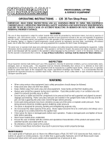
3. ASSEMBLY
Use the exploded drawing as your guide to assemble the press. Lay all parts and assemblies out in front
of you before beginning. The following procedure is recommended:
3.1 Attach one base to left upright and connect bar by using bolts, washers, lock washers and nuts.
Repeat the same step for the right upright.
3.2 Put the press frame in an upright position, attach one upper crossbeam to left and right upright by
using bolts, washers, lock washers and nuts.
3.3 Put another upper crossbeam into position and insert the under plate to the two upper crossbeams at
the same time, then secure this crossbeam to the posts with bolts, washers, lock washers and nuts.
3.4 Screw the upper round nut onto the ram, insert the ram into the hole in the under plate, then screw
the under round nut onto the ram and attach the saddle to the ram.
3.5 Join the tow working table together by inserting the four bolts through the bushings and the holes
in the bed frames, then secure the four bolts by tighten the washers, lock washers and nuts on it.
3.6 Insert bed frame pins into the holes of upright, then put the joined press bed frame onto the press
frame and bed frame pin.
3.7 Attach the pump a to the right post by using bolts and washers, then insert the handle tube into the
handle base.
3.8 Connect the hose connector to the connection nut and assemble the pressure gauge to the
pressure gauge connector which is on the top of the ram.
3.8 Tighten all bolts and nuts.
4. BEFORE FIRST USE
4.1 Before first use of this product, pour a teaspoon of good quality, air tool lubricant into the air supply
inlet of the lift control valve, connect to air supply to air supply and operate for 3 seconds to evenly
distribute lubricant.
4.2 Purge away air from the hydraulic system.
Manual operation system: open the release valve by turning it counterclockwise. Pump several full
stokes to eliminate any air in the system.
Air operating system: open the release valve by turning it counterclockwise. Connect the air inlet
fitting into the air supply hose lock fitting, then turn on the air valve letting the pump work for several
times to eliminate any air in the system.
4.3 Check all parts and conditions, if there is any part broken, stop using it and contact your supplier
immediately.

4
5. OPERATING INSTRUCTIONS
WARNING! Ensure that you read, understand and apply the safety instructions and warnings
before use.
WARNING! Ensure that you have familiarized yourself thoroughly with the product and the
hazards associated with its improper use.
5.1 Place the block onto the press bed frame, then insert work piece onto the heel block.
5.2 Close the release valve by turning it clockwise until it is firmly closed.
5.3 Connect the air inlet fitting into the shop air supply hose lock fitting, turn on the air valve to let the
pump work until serrated saddle nears work piece, then turn off the air valve. When air source is
unavailable, pump the handle until serrated saddle nears work piece.
5.4 Align work piece and ram to ensure center-loading.
5.5 Turn on the air valve (or pump the handle) to apply load onto the work piece.
5.6 When work is done, turn off the air valve (or stop pumping handle), slowly and carefully remove load
from work piece by turning the release valve counterclockwise in small increments.
5.7 Once ram has fully retracted, remove work piece from the press bed frame.
5.8 Disconnect the air inlet fitting from the air source.
6. MAINTENANCE
6.1 Clean the outside of the press with dry, clean and soft cloth and periodically lubricate the joints and all
moving parts with a light oil as needed.
6.2 When not in use, store the press in a dry location with ram and piston fully retracted..
6.3 When press efficiency drops, purge away air from hydraulic system as described in 4.2.
6.4 Check the hydraulic oil level: remove the filler nut on the top of the reservoir, if the oil is not adequate,
fill with high quality hydraulic jack oil as necessary, then replace the oil filler nut, purge away air from
the hydraulic system as described in 4.2.

5
7. EXPLODED DRAWING AND PARTS LIST

6
Part No.
Description
Qty.
Part No.
Description
Qty.
1
Pressure Gauge
1
17
Block
2
2
Nylon Washer
1
18
Working Table
2
3
Ram
1
19
Pin
2
4
Screw
1
20
Upright
2
5
Adaptor
1
21
Base
2
6
Upper Round Nut
1
22
Flat Washer
4
7
Ram Plate
1
23
Lock Washer
4
8
Under Round Nut
1
24
Nut
4
9
Bolt
8
25
Bolt
4
10
Upper Beam
2
26
Connect Bar
1
11
Flat Washer
8
27
Bolt
4
12
Lock Washer
8
28
Tube
4
13
Nut
8
29
Bolt
8
14
Flat Washer
16
30
Support Bar
4
15
Lock Washer
12
31
Bolt
4
16
Nut
12
32
Pump
1

7
Part No.
Description
Qty.
Part No.
Description
Qty.
1
Nut
1
12
Pressure Gauge Connector
1
2
Screw
1
13
Nut
1
3
U Ring
1
14
Pin
1
4
PTFE Washer
1
15
Nut
1
5
Piston
1
16
Ram Connector
1
6
O Ring
1
17
O Ring
1
7
Piston Rod
1
18
Dust Cap
1
8
Copper Washer
1
19
Ram
1
9
Screw
1
20
Limit Collar
1
10
Spring
1
2
Nylon Washer
1
11
Cap
1

8

9
Part No.
Description
Qty.
Part No.
Description
Qty.
P1
Cotter Pin
2
P25
O Ring
2
P2
Handle Base
1
P26
Screw
2
P3
Pump Core
1
P27
Cap
2
P4
PTFE Washer
1
P28
Screw
3
P5
O Ring
1
P29
Washer
3
P6
Base for Pump Core
1
P30
Spring
2
P7
Copper Washer
2
P31
Spring
1
P8
Pin
3
P32
Pump Base
1
P9
Bar
1
P33
Filter
2
P10
R Pin
1
P34
Washer
2
P11
Air Pump
1
P35
Oil Tank
1
P12
Steel Ball
4
P36
Bar
4
P13
U Limit
1
P37
Cover
1
P14
Lock Washer
1
P38
Nut
4
P15
Screw
1
P39
Screw
1
P16
Washer
1
P40
Air-inlet hose
1
P17
Base for release valve
1
P41
Air Valve
1
P18
Steel Ball
1
P42
Air hose connector
1
P19
O Ring
1
P43
Hose
1
P20
Release Valve
1
P44
Connector
1
P21
Steel Ball
2
P45
Dust Cap
1
P22
Base for steel ball
2
P46
Handle Tube
1
P23
Spring
2
2
Nylon Washer
1
P24
Screw
2
/