Page is loading ...

Product Category
1
SW2 DP • Setup Guide
The Extron SW2 DP is a two input, one output, DisplayPort switcher that switches DisplayPort video and embedded
multi-channel digital audio signals. The SW2 DP is HDCP-compliant and supports data rates up to 10.8 Gbps and computer
resolutions up to 2560x1600 @ 60 Hz. This guide provides basic instructions for an experienced installer to set up and
operate this switcher.
NOTE: For full installation, configuration, and operation details, see the SW2 DP User Guide, available at
www.extron.com.
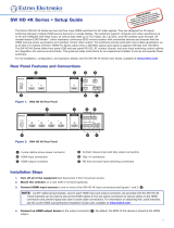
Rear Panel Features and Connections
12V
0.6A MAX
POWER
EDID
STORE
DEFAULT
21
STORED
RS-232 AUTO
Rx GTx
INPUTS OUTPUT EDID REMOTE
SW2 DP
3
2
1
6
7
5
4
a Power connector for 12 VDC, 1 A power supply e EDID Store button
b DisplayPort input connectors e EDID DIP switch
c DisplayPort output connector g RS-232 and auto-switching connector
d EDID Store LED
Installation Steps
1. Turn off all of the equipment and disconnect it from the power source.
2. (Optional) Mount the switcher on a rack shelf or furniture.
3. Connect DisplayPort sources to one or both of the SW2 DP input connectors (
b
on the rear panel diagram above).
4. Connect a DisplayPort output device to the output connector (
c
).
5. Connect control devices: Connect your computer to either of the following SW2 DP communication ports to
configure and control the switcher via SIS commands:
• RS-232 port — Connect the unterminated transmit,
receive, and ground wires of an RS-232 cable to the
first three pins on the provided 5-pole captive screw
plug, as shown in the illustration at right. Connect
the plug to the rear panel Remote shared connector
(
g
).
Connect the other end of the cable (terminated with
the female 9-pin HD connector) to your computer
serial port.
Protocol for the RS-232 port is 9600 baud, 8 data
bits, 1 stop bit, no parity.
• Cong port — Connect a USB A-to-mini B cable
between a USB port on your computer and the front
panel USB connector (
e
on the front panel diagram
on the next page) for USB control.
RS-232 Auto
Computer or
Control System
RS-232 Port
SW2 DP Switcher
Rear Panel
Remote Port
NOTE: If you use cable that has a drain
wire, tie the drain wire to ground
at both ends.
TxRx
G
Ground (G)
Transmit (Tx)
Receive (Rx)
Transmit (Tx)
Receive (Rx)
9-pin HD
Connector

68-2245-50 Rev. A
06 12
2
©2012 Extron Electronics All rights reserved. www.extron.com
Extron Headquarters
+800.633.9876 InsideUSA/CanadaOnly
Extron USA - West Extron USA - East
+1.714.491.1500 +1.919.850.1000
+1.714.491.1517 FAX +1.919.850.1001 FAX
ExtronEurope
+800.3987.6673
InsideEuropeOnly
+31.33.453.4040
+31.33.453.4050 FAX
ExtronAsia
+800.7339.8766
InsideAsiaOnly
+65.6383.4400
+65.6383.4664 FAX
ExtronJapan
+81.3.3511.7655
+81.3.3511.7656 FAX
ExtronChina
+4000.EXTRON
+4000.398766
InsideChinaOnly
+86.21.3760.1568
+86.21.3760.1566 FAX
Extron
Middle East
+971.4.2991800
+971.4.2991880 FAX
ExtronKorea
+82.2.3444.1571
+82.2.3444.1575 FAX
ExtronIndia
1800.3070.3777
InsideIndiaOnly
+91-80-3055.3777
+91 80 3055 3737 FAX
12V
- - A MAX
POWER
EDID
STORE
DEFAULT
21
STORED
RS-232 AUTO
RX GTX
INPUTS
OUTPUT
EDID
REMOTE
SW2 DP RS
6. (Optional) Enable auto-input switching. Attach the 5-pole
captive screw plug to the Remote connector (
g
on the rear
panel diagram on the previous page) if this was not done in
step 5 for the RS-232 connection. Use a jumper wire to short pins 4
and 5 of the shared plug together (see the illustration at right).
When auto-input switching is in effect, the green Auto Switch LED
on the front panel lights (
a
on the diagram below).
7. If necessary, wire a 2-pole captive screw connector (provided) to
your Extron power supply as shown below.
Captive Screw Connector
Tie Wrap
Heat
Shrink
1/8”
(3 mm)
7/8”
(22 mm)
3/16”
(5 mm) Max.
ATTENTION: • The power supply must not be permanently fixed to the
building structure or similar structures.
• The power supply must not be located within environmental
air handling spaces or the wall cavity.
8. Set the rear panel EDID DIP switch (switch 1, on the left) as follows:
• Set the switch to Stored (down) if you want to store the EDID (resolution, refresh rate, and
clocking rate) of the connected display at the SW2 DP output (see the illustration at right), then
press the recessed EDID Store button. The EDID LED flashes amber, then lights steadily green
when the EDID has been stored.
• Set the switch to Default (up) to select the Extron DisplayPort default EDID of 1920x1080 @
60 Hz with 2-channel audio.
NOTE: DIP switch 2 (on the right) is not functional.
9. Power on the output display.
10. Connect power to the switcher.
11. Power on the source devices.
Front Panel Features
CONFIG
AUTO
SWITCH
SW2 DP
DISPLAYPORT SWITCHER
1 2
12
SIGNAL
INPUTS OUTPUT
HDCP
INPUTS
3
1
4
2
5
a Auto Switch LED
b Input Selection buttons
c Signal Status LEDs
d HDCP Status LEDs
e USB Config port
EDID
STORE
DEFAULT
STORED
EDID
/