RoboteQ AX2850 User manual
- Category
- Measuring, testing & control
- Type
- User manual

AX2550
AX2850
Dual Channel
High Power
Digital Motor
Controller
User’s Manual
v1.9b, June 1, 2007
visit www.roboteq.com to download the latest revision of this manual
©Copyright 2003-2007 Roboteq, Inc.

2 AX2550 Motor Controller User’s Manual Version 1.9b. June 1, 2007

AX2550 Motor Controller User’s Manual 3
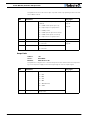
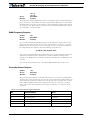
Revision History
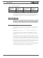
The information contained in this manual is believed to be accurate and reliable. However,
it may contain errors that were not noticed at time of publication. User’s are expected to
perform their own product validation and not rely solely on data contained in this manual.
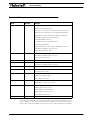
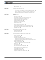
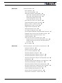
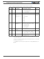
Revision History
Date Version Changes
June 1, 2007 1.9b Added Output C active when Motors On
Fixed Encoder Limit Switches
Protection in case of Encoder failure in Closed Loop Speed
Added Short Circuit Protection (with supporting hardware)
Added Analog 3 and 4 Inputs (with supporting hardware)
Added Operating Mode Change on-the-fly
Changeable PWM frequency
Selectable polarity for Dead Man Switch
Modified Flashing Pattern
Separate PID Gains for Ch1 and C2, changeable on-the-fly
Miscellaneous additions and correction
Added Amps Calibration option
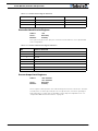
January 10, 2007 1.9 Changed Amps Limit Algorithm
Miscellaneous additions and correction
Console Mode in Roborun
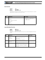
March 7, 2005 1.7b Updated Encoder section.
February 1, 2005 1.7 Added Position mode support with Optical Encoder
Miscellaneous additions and corrections
April 17, 2004 1.6 Added Optical Encoder support
March 15, 2004 1.5 Added finer Amps limit settings
Enhanced Roborun utility
August 25, 2003 1.3 Added Closed Loop Speed mode
Added Data Logging support
Removed RC monitoring
August 15, 2003 1.2 Modified to cover AX2550 controller design
Changed Power Connection section
April 15, 2003 1.1 Added analog mode section
Added position mode section
Added RCRC monitoring feature
Updated Roborun utility section
Modified RS232 watchdog
March 15, 2003 1.0 Initial Release

4 AX2550 Motor Controller User’s Manual Version 1.9b. June 1, 2007

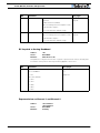
AX2550 Motor Controller User’s Manual 5
Revision History 3
SECTION 1 Important Safety Warnings 13
This product is intended for use with rechargeable batteries 13
Do not Connect to a RC Radio with a Battery Attached 13
Beware of Motor Runaway in Improperly Closed Loop 13
SECTION 2 AX2550
Quick Start 15
What you will need 15
Locating the Switches, Wires and Connectors 15
Connecting to the Batteries and Motors 17
Connecting to the 15-pin Connector 18
Connecting the R/C Radio 19
Powering On the Controller 20
Button Operation 20
Default Controller Configuration 21
Connecting the controller to your PC using Roborun 22
Obtaining the Controller’s Software Revision Number 23
Exploring further 24
SECTION 3 AX2550 Motor Controller Overview 25
Product Description 25
Technical features 26
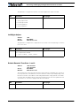
SECTION 4 Connecting Power and Motors to the Controller 29
Power Connections 29
Controller Power 30
Controller Powering Schemes 32
Powering the Controller from a single Battery 32
Powering the Controller Using a Main and Backup Battery 33
Connecting the Motors 34
Single Channel Operation 35
Converting the AX2550 to Single Channel 35
Power Fuses 36
Wire Length Limits 37
Electrical Noise Reduction Techniques 37
Power Regeneration Considerations 37
Overvoltage Protection 38
Undervoltage Protection 38
Using the Controller with a Power Supply 39

6 AX2550 Motor Controller User’s Manual Version 1.9b. June 1, 2007
SECTION 5 General Operation 41
Basic Operation 41
Input Command Modes 41
Selecting the Motor Control Modes 42
Open Loop, Separate Speed Control 42
Open Loop, Mixed Speed Control 42
Closed Loop Speed Control 43
Close Loop Position Control 43
User Selected Current Limit Settings 44
Temperature-Based Current Limitation 44
Battery Current vs. Motor Current 45
Regeneration Current Limiting 46
Programmable Acceleration 47
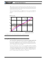
Command Control Curves 48
Left / Right Tuning Adjustment 49
Activating Brake Release or Separate Motor Excitation 51
Emergency Shut Down Using Controller Switches 51
Emergency Stop using External Switch 51
Inverted Operation 52
Special Use of Accessory Digital Inputs 52
Using the Inputs to Activate the Buffered Output 52
Using the Inputs to turn Off/On the Power MOSFET
transistors 52
Self-Test Mode 53
SECTION 6 Connecting Sensors and Actuators to Input/Outputs 55
AX2550 Connections 55
AX2550’s Inputs and Outputs 57
I/O List and Pin Assignment 58
Connecting devices to Output C 59
Connecting Switches or Devices to Input E 60
Connecting Switches or Devices to Input F 61
Connecting Switches or Devices to EStop/Invert Input 62
Analog Inputs 63
Connecting Position Potentiometers to Analog Inputs 63
Connecting Tachometer to Analog Inputs 64
Connecting External Thermistor to Analog Inputs 66
Using the Analog Inputs to Monitor External Voltages 67
Connecting User Devices to Analog Inputs 67
Internal Voltage Monitoring Sensors 68
Internal Heatsink Temperature Sensors 68
Temperature Conversion C Source Code 69

AX2550 Motor Controller User’s Manual 7
SECTION 7 Installing, Connecting and Using the Encoder Module 71
Optical Incremental Encoders Overview 71
Recommended Encoder Types 72
Installing the Encoder Module 73
Connecting the Encoder 75
Cable Length and Noise Considerations 76
Motor - Encoder Polarity Matching 76
Voltage Levels, Thresholds and Limit Switches 76
Wiring Optional Limit Switches 78
Wiring Limit Switches Without Encoders 79
Effect of Limit Switches 79
Using the Encoder Module to Measure Distance 80
Using the Encoder to Measure Speed 80
Using the Encoder to Track Position 81
RS232 Communication with the Encoder Module 82
Encoder Testing and Setting Using the PC Utility 83
SECTION 8 Closed Loop Position Mode 85
Mode Description 85
Selecting the Position Mode 85
Position Sensor Selection 86
Sensor Mounting 86
Feedback Potentiometer wiring 87
Feedback Potentiometer wiring in RC or RS232 Mode 87
Feedback Potentiometer wiring in Analog Mode 88
Analog Feedback on Single Channel Controllers 89
Feedback Wiring in RC or RS232 Mode on Single Channel
Controllers 89
Feedback Wiring in Analog Mode on Single Channel
Controllers 89
Using Optical Encoders in Position Mode 90
Sensor and Motor Polarity 90
Encoder Error Detection and Protection 91
Adding Safety Limit Switches 91
Using Current Limiting as Protection 93
Control Loop Description 93
PID tuning in Position Mode 94
SECTION 9 Closed Loop Speed Mode 97
Mode Description 97
Selecting the Speed Mode 97
Using Optical Encoder for Speed Feedback (AX2850 only) 98

8 AX2550 Motor Controller User’s Manual Version 1.9b. June 1, 2007
Tachometer or Encoder Mounting 98
Tachometer wiring 98
Speed Sensor and Motor Polarity 99
Adjust Offset and Max Speed 100
Control Loop Description 100
PID tuning in Speed Mode 102
SECTION 10 Normal and
Fault Condition LED Messages 103
Use of the LED Display 103
Motor Direction Status 104
Fault Messages 105
No Control 105
Tem po ra r y Fa ul t s 106
Permanent Faults 106
Self-Test Display 106
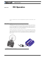
SECTION 11 R/C Operation 109
Mode Description 109
Selecting the R/C Input Mode 110
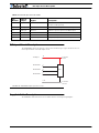
Connector I/O Pin Assignment (R/C Mode) 110
R/C Input Circuit Description 111
Supplied Cable Description 111
Powering the Radio from the controller 11 2
Connecting to a Separately Powered Radio 114
Operating the Controller in R/C mode 11 4
Reception Watchdog 115
R/C Transmitter/Receiver Quality Considerations 116
Joystick Deadband Programming 117
Command Control Curves 118
Left/Right Tuning Adjustment 118
Joystick Calibration 118
Automatic Joystick Calibration 119
Activating the Accessory Outputs 120
Data Logging in R/C Mode 121
SECTION 12 Analog Control and Operation 123
Mode Description 123
Connector I/O Pin Assignment (Analog Mode) 124
Connecting to a Voltage Source 125
Connecting a Potentiometer 125
Selecting the Potentiometer Value 126

AX2550 Motor Controller User’s Manual 9
Analog Deadband Adjustment 127
Power-On Safety 128
Under Voltage Safety 128
Data Logging in Analog Mode 128
SECTION 13 Serial (RS-232) Controls and Operation 131
Use and benefits of RS232 131
Connector I/O Pin Assignment (RS232 Mode) 132
Cable configuration 133
Extending the RS232 Cable 133
Communication Settings 134
Establishing Manual Communication with a PC 134
RS232 Communication with the Encoder Module 135
Entering RS232 from R/C or Analog mode 136
Data Logging String in R/C or Analog mode 136
RS232 Mode if default 137
Commands Acknowledge and Error Messages 137
Character Echo 137
Command Acknowledgement 137
Command Error 137
Watchdog time-out 137
RS-232 Watchdog 138
Controller Commands and Queries 138
Set Motor Command Value 139
Set Accessory Output 139
Query Power Applied to Motors 140
Query Amps from Battery to each Motor Channel 140
Query Analog Inputs 140
Query Heatsink Temperatures 141
Query Battery Voltages 141
Query Digital Inputs 142
Reset Controller 142
Accessing & Changing Configuration Parameter in Flash 143
Apply Parameter Changes 143
Flash Configuration Parameters List 144
Input Control Mode 145
Motor Control Mode 145
Amps Limit 146
Acceleration 147
Input Switches Function 147
RC Joystick or Analog Deadband 148
Exponentiation on Channel 1 and Channel 2 148
Left/Right Adjust 149
Default Encoder Time Base 1 and 2 149
Default Encoder Distance Divider 150

10 AX2550 Motor Controller User’s Manual Version 1.9b. June 1, 2007
Default PID Gains 150
Joystick Min, Max and Center Values 150
Reading & Changing Operating Parameters at Runtime 151
Operating Modes Registers 152
Read/Change PID Values 152
PWM Frequency Register 153
Controller Status Register 153
Controller Identification Register 154
Current Amps Limit Registers 154
RS232 Encoder Command Set 155
Read Encoder Counter 155
Set/Reset Encoder Counters and Destination Registers 155
Read Speed 156
Read Distance 157
Read Speed/Distance 157
Read Encoder Limit Switch Status 157
Read / Modify Encoder Module Registers and Parameters 158
Register Description 160
Encoder Hardware ID code 160
Switch Status 160
Speed or Distance 1 or 2 160
Counter Read/Write Mailbox 161
Counter 1 and 2 161
Destination Register 1 and 2 161
Distance 1 and 2 162
Speed 1 and 2 162
Time Base 1 and 2 162
Encoder Threshold 162
Distance Divider 162
Counter Read Data Format 163
Encoder Testing and Setting Using the PC Utility 163
Automatic Switching from RS232 to RC Mode 165
Analog and R/C Modes Data Logging String Format 166
Data Logging Cables 166
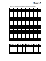
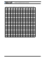
Decimal to Hexadecimal Conversion Table 167
SECTION 14 Configuring the Controller using the Switches 171
Programming Methods 171
Programming using built-in Switches and Display 171
Entering Programming Mode 172
Changing parameters 173
The Special Case of Joystick Calibration 173
Restoring factory defaults 173
Exiting the Parameter Setting Mode 174
Programmable Parameters List 174

AX2550 Motor Controller User’s Manual 11
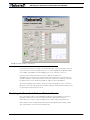
SECTION 15 Using the Roborun Configuration Utility 177
System Requirements 177
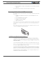
Downloading and Installing the Utility 177
Connecting the Controller to the PC 178
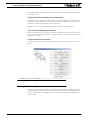
Roborun Frame, Tab and Menu Descriptions 179
Getting On-Screen Help 180
Loading, Changing Controller Parameters 181
Control Settings 181
Power Settings 182
Analog or R/C Specific Settings 183
Closed Loop Parameters 184
Encoder Setting and Testing 184
Encoder Module Parameters Setting 185
Exercising the Motors 186
Viewing Encoder Data 186
Running the Motors 186
Logging Data to Disk 189
Connecting a Joystick 190
Using the Console 191
Viewing and Logging Data in Analog and R/C Modes 192
Loading and Saving Profiles to Disk 192
Operating the AX2550 over a Wired or Wireless LAN 193
Updating the Controller’s Software 194
Updating the Encoder Software 195
Creating Customized Object Files 195
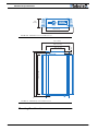
SECTION 16 Mechanical Specifications 197
Mechanical Dimensions 197
Mounting Considerations 198
Thermal Considerations 199
Attaching the Controller Directly to a Chassis 199
Wire Dimensions 199
Weight 200

12 AX2550 Motor Controller User’s Manual Version 1.9b. June 1, 2007

AX2550 Motor Controller User’s Manual 13
SECTION 1 Important Safety
Warnings
Read this Section First
The AX2550 is a high power electronics device. Serious damage, including fire,
may occur to the unit, motors, wiring and batteries as a result of its misuse.
Please review the User’s Manual for added precautions prior to applying full
battery or full load power.
This product is intended for use with rechargeable batteries
Unless special precautions are taken, damage to the controller and/or power supply
may occur if operated with a power supply alone. See“Power Regeneration Consid-
erations” on page 37 of the Users Manual. Always keep the controller connected
to the Battery. Use the Power Control input to turn On/Off.
Do not Connect to a RC Radio with a Battery Attached
Without proper protection, a battery attached to an RC Radio may inject its voltage
directly inside the controller’s sensitive electronics. See
Beware of Motor Runaway in Improperly Closed Loop
Wiring or polarity errors between the feedback device and motor in position or
closed loop position mode may cause the controller to runaway with no possibility
to stop it until power is turned off.

Important Safety Warnings
14 AX2550 Motor Controller User’s Manual Version 1.9b. June 1, 2007

AX2550 Motor Controller User’s Manual 15
SECTION 2 AX2550
Quick Start
This section will give you the basic information needed to quickly install, setup and
run your AX2550 controller in a minimal configuration. The AX2850 is a version of
the AX2550 controller with the addition of Optical Encoder inputs.
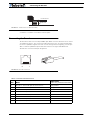
What you will need
For a minimal installation, gather the following components:
• One AX2550 Controller and its provided cables
• 12V to 40V high capacity, high current battery
• One or two brushed DC motors
• One R/C to DB15 connector (provided)
• Miscellaneous wires, connectors, fuses and switch
Locating the Switches, Wires and Connectors
Take a moment to familiarize yourself with the controller’s wires, switches and con-
nectors.

AX2550 Quick Start
16 AX2550 Motor Controller User’s Manual Version 1.9b. June 1, 2007
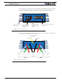
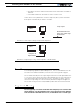
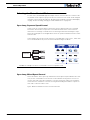
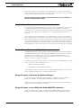
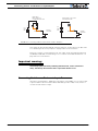
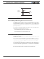
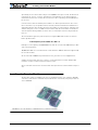
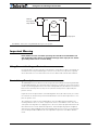
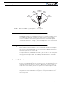
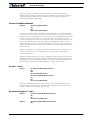
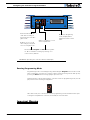
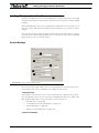
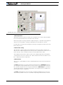
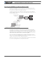
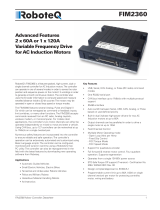
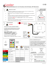
The front side (shown in Figure 1) contains the buttons and display needed to operate and
monitor the controller. The 15-pin connector provides the connection to the R/C radio, joy-
stick or microcomputer, as well as connections to optional switches and sensors.
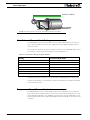
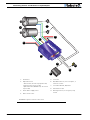
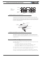
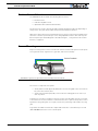
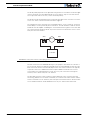
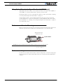
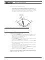
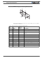
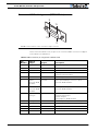
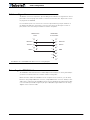
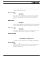
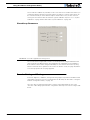
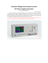
At the back of the controller (shown in the figure below) are located all the wires that must
be connected to the batteries and the motors.
Program Set
Reset
Connector to Receiver/Controls
and sensors
Operating Status
and Program LED
Display
Controller Configu-
ration buttons
FIGURE 1. Front Controller Layout
Connector to
Optical Encoders
(AX2850 only)
Controller Power
Ground (-)
Black
(top)
Power Control
Yellow
Motor 2
12 to 40V (+)
Red
Ground (-)
Black
Motor(+)
Yellow or
White
Motor (-)
Green
Motor 1
12 to 40V (+)
Red
Motor (-)
Green
Motor (+)
White
FIGURE 2. Rear Controller Layout

AX2550 Motor Controller User’s Manual 17
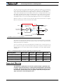
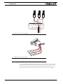
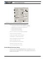
Connecting to the Batteries and Motors
Connecting to the Batteries and Motors
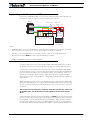
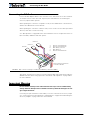
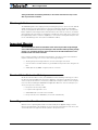
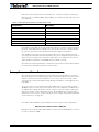
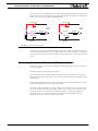
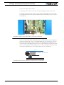
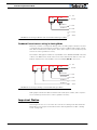
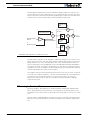
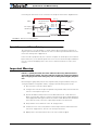
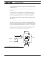
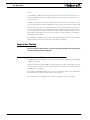
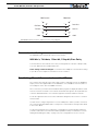
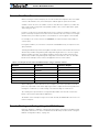
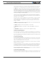
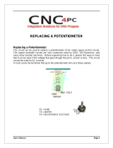
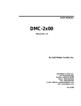
Connection to the batteries and motors is shown in the figure below and is done by con-
necting the set of wires coming out from the back of the controller.
1- Connect each motor to one of the two M+ and M- cables pairs. Make sure to respect
the polarity, otherwise the motor(s) may spin in the opposite direction than expected
2- Connect the two thick black wires to the minus (-) terminal of the battery that will be
used to power the motors. Connect the two thick red wires the two VMot terminals to the
plus (+) terminal of the battery. The motor battery may be of 12 to 40 Volts. There is no
need to insert a separate switch on Power cables, although one is suggested for Emer-
gency disconnect. See “Controller Power” on page 30 for a detailed discussion and more
wiring options.
Avoid extending the length of wires from the battery to the controller as the added induc-
tance may cause damage to the controller when operating at high currents. Try extending
the motor wires instead since the added inductance on the motor side of the controller is
not harmful.
The two red wires are connected to each other inside the controller. The same is true
for the black wires. You should wire each pair together as shown in the diagram
above.
3- The yellow Power Control wire and the thin black wire MUST be connected to Ground to
turn the Controller Off. For turning the controller On, even though the Power Control may
be left floating, whenever possible pull it to an unfused12V or higher voltage to keep the
controller logic solidly On. You may use a separate battery to keep the controller alive as
the main Motor battery discharges. Refer to the chapter “Connecting Power and Motors to
12V to 24V
Motor Battery
Power switch
On
Off
Optional
Emergency
Disconnect
Optional
Diode
-
-
+
+
Motor1
Motor2
Controller
Fuse
VMot
VMot
M1-
M1+
PwrCtrl
GND
GND
GND
M2+
M2-
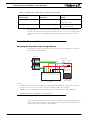
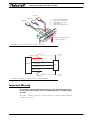
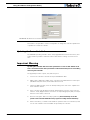
Notes:
- The Battery Power connection are doubled in order to provide the maximum current to the controller. If
only one motor is used, only one set of motor power cables needs to be connected.
- Typically, 1, 2 or 3 x 12V batteries are connected in series to reach 12, 24 or 36V respectively.
- The Power Control wire MUST be used to turn On and Off the controller.
FIGURE 3. AX2550 Electrical Power Wiring Diagram

AX2550 Quick Start
18 AX2550 Motor Controller User’s Manual Version 1.9b. June 1, 2007
the Controller” on page 29 for more information about batteries and other connection
options.
Important Warning
Do not rely on cutting power to the controller for it to turn off if the Power Control is
left floating. If motors are spinning because the robot is pushed are pushed or
because of inertia, they will act as generators and will turn the controller, possibly in
an unsafe state. ALWAYS ground the Power Control wire to turn the controller Off
and keep it Off.
Important Warning
The controller includes large capacitors. When connecting the Motor Power Cables,
a spark will be generated at the connection point. This is a normal occurrence and
should be expected.
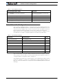
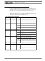
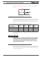
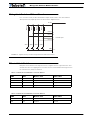
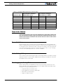
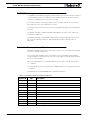
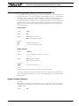
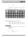
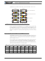
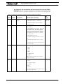
Connecting to the 15-pin Connector
The controller’s I/O are located on it’s standard 15-pin D-Sub Connector. The functions of
some pins varies depending on controller model and operating mode. Pin assignment is
found in the table below.
Pin
Signal
RC Mode RS232 Mode Analog Mode
1 2A Digital Output C (same as pin 9)
2TxData
3 RC Ch1 RxData Unused
4 RC Ch 2 Digital Input F
5 Ground Out
6 Ground In
(Unused on RevB Hardware)
7 +5V In
(Unused on RevB Hardware)
8 Digital Input E (Not available when Encoder module is present)
and Analog Input 4 (on RevB hardware only)
9 2A Digital Output C (same as pin 1)
10 Analog Input 2
11 Analog Input 1
12 Analog Input 3 (on RevB hardware)
13 Ground Out
14 +5V Out (100mA max.)
15 Emergency Stop or Invert Switch input

AX2550 Motor Controller User’s Manual 19
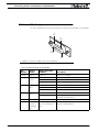
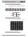
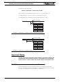
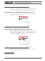
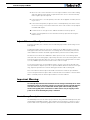
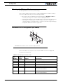
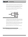
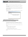
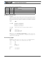
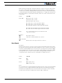
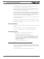
Connecting the R/C Radio
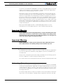
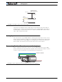
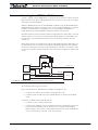
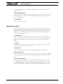
Connecting the R/C Radio
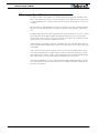
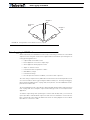
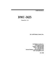
Connect the R/C adapter cables to the controller on one side and to two or three channels
on the R/C receiver on the other side. If present, the third channel is for activating the
accessory outputs and is optional.
When operating the controller in “Separate” mode, the wire labelled Ch1 controls Motor1,
and the wire labelled Ch2 controls Motor2.
When operating the controller in “Mixed” mode, Ch1 is used to set the robot’s speed and
direction, while Ch2 is used for steering.
See “R/C Operation” on page 109 of the User’s Manual for a more complete discussion on
R/C commands, calibration and other options.
This wiring - with the wire loop uncut - assumes that the R/C radio will be powered by the
AX2550 controller. Other wiring options are described in “R/C Operation” on page 109 of
the User’s Manual.
Important Warning
Do not connect a battery to the radio when the wire loop is uncut. The RC battery
voltage will flow directly into the controller and cause permanent damage if its volt-
age is higher than 5.5V.
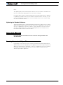
Connecting the optional channel 3 will enable you to turn on and off the accessory output.
See “Connecting Sensors and Actuators to Input/Outputs” on page 55 and “Activating the
Accessory Outputs” on page 120 of the User’s Manual.
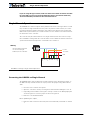
8
9
15
Pin 1
Channel 1
Wire loop bringing power from
controller to RC radio
Channel 2
3: Channel 1 Command Pulses
4: Channel 2 Command Pulses
6: Radio battery (-) Ground
7: Radio battery (+)
8: Channel 3 Command Pulses
Channel 3
FIGURE 4. R/C connector wiring for 3 channels and battery elimination (BEC)

AX2550 Quick Start
20 AX2550 Motor Controller User’s Manual Version 1.9b. June 1, 2007
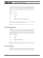
Powering On the Controller
Important reminder: There is no On-Off switch on the controller. You must insert a switch
on the controller’s power wire as described in section“Connecting to the Batteries and
Motors” on page 17.
To power the controller, center the joystick and trims on the R/C transmitter. In Analog
mode, center the command potentiomenter or joystick.Then turn on the switch that you
have placed on the on the Power Control input.
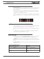
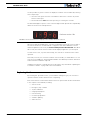
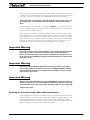
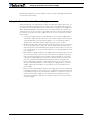
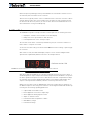
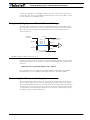
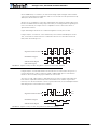
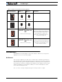
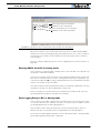
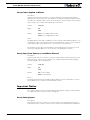
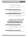
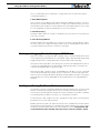
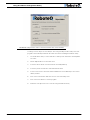
If the R/C transmitter and/or receiver is powered off, the display on the controller will alter-
nate the letters spelling “no ctrl” to indicate that it is On but is not receiving a control sig-
nal.
Turn the R/C transmitter On. The “no ctrl” scrolling message will disappear and the display
will show steady patterns depending on the motor’s selected direction.
Move the joystick on the transmitter to activate the motors to the desired speed and direc-
tion.
See “R/C Operation” on page 109 of the User’s Manual for a detailed description of the
many features and options available in the R/C mode.
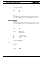
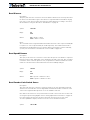
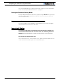
Button Operation
The AX2550 has three buttons: Set, Program and Reset. These buttons are not needed
for normal operation, as the controller is immediately operational upon power up.
The Reset button will restart the controller. This button is recessed and you will need a
paper clip to press it. Reset is also accomplished by turning the controller’s power Off and
back On.
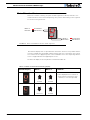
The Set and Program buttons have the following functions depending how and when they
are pressed:
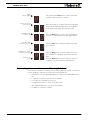
TABLE 1. AX2550 Buttons Function
Prog and Set button status Function
Press and hold Program alone during reset or power up Enter the Programming Mode.
Press and hold Set alone during reset of power up Enter Self-Test mode. See “Self-Test
Mode” on page 53 of the User’s Manual
Press and hold Program and Set together during reset or
power up
Reset configuration parameters to factory
default
FIGURE 5. “no control” scroll message indicates no valid R/C signal is present
Page is loading ...
Page is loading ...
Page is loading ...
Page is loading ...
Page is loading ...
Page is loading ...
Page is loading ...
Page is loading ...
Page is loading ...
Page is loading ...
Page is loading ...
Page is loading ...
Page is loading ...
Page is loading ...
Page is loading ...
Page is loading ...
Page is loading ...
Page is loading ...
Page is loading ...
Page is loading ...
Page is loading ...
Page is loading ...
Page is loading ...
Page is loading ...
Page is loading ...
Page is loading ...
Page is loading ...
Page is loading ...
Page is loading ...
Page is loading ...
Page is loading ...
Page is loading ...
Page is loading ...
Page is loading ...
Page is loading ...
Page is loading ...
Page is loading ...
Page is loading ...
Page is loading ...
Page is loading ...
Page is loading ...
Page is loading ...
Page is loading ...
Page is loading ...
Page is loading ...
Page is loading ...
Page is loading ...
Page is loading ...
Page is loading ...
Page is loading ...
Page is loading ...
Page is loading ...
Page is loading ...
Page is loading ...
Page is loading ...
Page is loading ...
Page is loading ...
Page is loading ...
Page is loading ...
Page is loading ...
Page is loading ...
Page is loading ...
Page is loading ...
Page is loading ...
Page is loading ...
Page is loading ...
Page is loading ...
Page is loading ...
Page is loading ...
Page is loading ...
Page is loading ...
Page is loading ...
Page is loading ...
Page is loading ...
Page is loading ...
Page is loading ...
Page is loading ...
Page is loading ...
Page is loading ...
Page is loading ...
Page is loading ...
Page is loading ...
Page is loading ...
Page is loading ...
Page is loading ...
Page is loading ...
Page is loading ...
Page is loading ...
Page is loading ...
Page is loading ...
Page is loading ...
Page is loading ...
Page is loading ...
Page is loading ...
Page is loading ...
Page is loading ...
Page is loading ...
Page is loading ...
Page is loading ...
Page is loading ...
Page is loading ...
Page is loading ...
Page is loading ...
Page is loading ...
Page is loading ...
Page is loading ...
Page is loading ...
Page is loading ...
Page is loading ...
Page is loading ...
Page is loading ...
Page is loading ...
Page is loading ...
Page is loading ...
Page is loading ...
Page is loading ...
Page is loading ...
Page is loading ...
Page is loading ...
Page is loading ...
Page is loading ...
Page is loading ...
Page is loading ...
Page is loading ...
Page is loading ...
Page is loading ...
Page is loading ...
Page is loading ...
Page is loading ...
Page is loading ...
Page is loading ...
Page is loading ...
Page is loading ...
Page is loading ...
Page is loading ...
Page is loading ...
Page is loading ...
Page is loading ...
Page is loading ...
Page is loading ...
Page is loading ...
Page is loading ...
Page is loading ...
Page is loading ...
Page is loading ...
Page is loading ...
Page is loading ...
Page is loading ...
Page is loading ...
Page is loading ...
Page is loading ...
Page is loading ...
Page is loading ...
Page is loading ...
Page is loading ...
Page is loading ...
Page is loading ...
Page is loading ...
Page is loading ...
Page is loading ...
Page is loading ...
Page is loading ...
Page is loading ...
Page is loading ...
Page is loading ...
Page is loading ...
Page is loading ...
Page is loading ...
Page is loading ...
Page is loading ...
Page is loading ...
Page is loading ...
Page is loading ...
Page is loading ...
Page is loading ...
Page is loading ...
Page is loading ...
Page is loading ...
Page is loading ...
Page is loading ...
-
 1
1
-
 2
2
-
 3
3
-
 4
4
-
 5
5
-
 6
6
-
 7
7
-
 8
8
-
 9
9
-
 10
10
-
 11
11
-
 12
12
-
 13
13
-
 14
14
-
 15
15
-
 16
16
-
 17
17
-
 18
18
-
 19
19
-
 20
20
-
 21
21
-
 22
22
-
 23
23
-
 24
24
-
 25
25
-
 26
26
-
 27
27
-
 28
28
-
 29
29
-
 30
30
-
 31
31
-
 32
32
-
 33
33
-
 34
34
-
 35
35
-
 36
36
-
 37
37
-
 38
38
-
 39
39
-
 40
40
-
 41
41
-
 42
42
-
 43
43
-
 44
44
-
 45
45
-
 46
46
-
 47
47
-
 48
48
-
 49
49
-
 50
50
-
 51
51
-
 52
52
-
 53
53
-
 54
54
-
 55
55
-
 56
56
-
 57
57
-
 58
58
-
 59
59
-
 60
60
-
 61
61
-
 62
62
-
 63
63
-
 64
64
-
 65
65
-
 66
66
-
 67
67
-
 68
68
-
 69
69
-
 70
70
-
 71
71
-
 72
72
-
 73
73
-
 74
74
-
 75
75
-
 76
76
-
 77
77
-
 78
78
-
 79
79
-
 80
80
-
 81
81
-
 82
82
-
 83
83
-
 84
84
-
 85
85
-
 86
86
-
 87
87
-
 88
88
-
 89
89
-
 90
90
-
 91
91
-
 92
92
-
 93
93
-
 94
94
-
 95
95
-
 96
96
-
 97
97
-
 98
98
-
 99
99
-
 100
100
-
 101
101
-
 102
102
-
 103
103
-
 104
104
-
 105
105
-
 106
106
-
 107
107
-
 108
108
-
 109
109
-
 110
110
-
 111
111
-
 112
112
-
 113
113
-
 114
114
-
 115
115
-
 116
116
-
 117
117
-
 118
118
-
 119
119
-
 120
120
-
 121
121
-
 122
122
-
 123
123
-
 124
124
-
 125
125
-
 126
126
-
 127
127
-
 128
128
-
 129
129
-
 130
130
-
 131
131
-
 132
132
-
 133
133
-
 134
134
-
 135
135
-
 136
136
-
 137
137
-
 138
138
-
 139
139
-
 140
140
-
 141
141
-
 142
142
-
 143
143
-
 144
144
-
 145
145
-
 146
146
-
 147
147
-
 148
148
-
 149
149
-
 150
150
-
 151
151
-
 152
152
-
 153
153
-
 154
154
-
 155
155
-
 156
156
-
 157
157
-
 158
158
-
 159
159
-
 160
160
-
 161
161
-
 162
162
-
 163
163
-
 164
164
-
 165
165
-
 166
166
-
 167
167
-
 168
168
-
 169
169
-
 170
170
-
 171
171
-
 172
172
-
 173
173
-
 174
174
-
 175
175
-
 176
176
-
 177
177
-
 178
178
-
 179
179
-
 180
180
-
 181
181
-
 182
182
-
 183
183
-
 184
184
-
 185
185
-
 186
186
-
 187
187
-
 188
188
-
 189
189
-
 190
190
-
 191
191
-
 192
192
-
 193
193
-
 194
194
-
 195
195
-
 196
196
-
 197
197
-
 198
198
-
 199
199
-
 200
200


RoboteQ AX2850 User manual
- Category
- Measuring, testing & control
- Type
- User manual
Ask a question and I''ll find the answer in the document
Finding information in a document is now easier with AI

Other documents
-
 Consew CSM1000 User manual
-
Gill LED SCROLLING DISPLAY Operating instructions
-
 Riden Constant RD6006/ RD6006-W Voltage and Constant Current DC Power Supply User manual
-
 CNC4PC C82 Multifunction Cnc Board User manual
-
 Lodar M2HP03 User manual
-
Eaton Vickers EHH-AMP-702-D-10 Setup Procedure
-
Cortex VEXnet User manual
-
 Galil DMC-2270 User manual
-
Dakota Digital PAC-3200 Technical Manual
-
 Galil Home Security System DMC-3425 User manual


