Page is loading ...

MAN#650129A
1
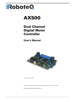
PAC-3200
DUAL LINEAR MOTOR / ACTUATOR CONTROLLER
W/ CURRENT SENSING AUTO REVERSE
PRESET BUTTONS
DUAL LINEAR MOTOR CONTROLLER
WITH SAFETY REVERSE
PAC-3200
MOTOR 2
MOTOR 1
RED
BLACK
YELLOW
PURPLE
PINK
WHITE w/ RED
BROWN
WHITE w/ BLACK
Preset 1 ground activated(optional)
Preset 3 ground activated(optional)
Preset 2 ground activated(optional)
Manual up ground activated(optional)
Manual down ground activated(optional)
ACC power +12 V when key ON
Ground to
battery/chassis
MOTOR 2
POS
NEG
20 amp
FUSE
BATTERY
MOTOR 1
MUST BE USED WITH
DAKOTA DIGITAL PART
LACT-6, LACT-8, LACT-10
Constant +12V
Power
MAIN
#1 ACC DISABLE
#2 AUTO MOVE
#3 SENSITIVITY
#4 MOTOR 1
#5 MOTOR 2
#6 NOT USED
or LACT-12
Switch 1 (safety disable, page 3 for more detail)
ON - disables preset buttons and external presets when key is ON
OFF - buttons work the entire time key ON/OFF
Note: the external manual UP/DOWN will work all of the time
Switch 2 (auto move feature, page 3 for more detail)
ON - enable auto move: when key ON move to position 1
when key OFF move to position 2
OFF - disable auto move feature
Switch 3 (auto reverse sensitivity, page 3 for more detail)
ON - high sensitivity
OFF - low sensitivity
Switch 4 and Switch 5 (single motor adjust and auto reverse enable)
SW4 ON & SW5 OFF - move motor 1 only
SW4 OFF & SW5 ON - move motor 2 only
SW4 & SW5 ON - auto reverse enabled
SW4 & SW5 OFF - auto reverse disabled
Switch 6 - NOT USED

MAN#650129A
2
Features
The PAC-3200 is designed to control two linear motors at the same time. It is
intended to be used to lift heavier trunk lids and toppers / Tonneau covers that require more
than one motor. The PAC-3200 has many convenient features which include:
Three user programmable heights
Stylish, lighted push button control
Remote, ground activated, input lines to control the system with a remote system
Safety auto reverse
Auto move to position when the vehicle is turned on / off
Single motor adjustment
Wiring
BLACK - Connect to a main ground location
RED - Connect to fused constant 12 volt power
YELLOW - Connect to switched 12 volt power
(An accessory terminal will work for this)
PURPLE - Optional remote ground trigger for preset 3
PINK - Optional remote ground trigger for preset 1
BROWN - Optional remote ground trigger for preset 2
WHITE w/ BLACK - Optional emergency switch (ground for manual down)
WHITE w/ RED - Optional emergency switch (ground for manual up)
PRESET BUTTONS - To mating 4 pin connector
Mounting
The linear actuators should be mounted following the instructions supplied with them.
It is very important to mount the motors correctly or damage to the vehicle could result.
Remember that the motors should be mounted so they are completely closed when the
trunk/cover being lifted is shut all the way. Also insure that the motors can not rise too far
and cause damage.
The controller should be mounted inside the vehicle and all wires routed through the
vehicle to appropriate connections or motors. The controller should NOT be mounted in
the trunk area or under the cover being lifted for emergency service access. It is also
recommended that manual up/down switches be installed in case of emergency.
The preset buttons require an oval hole to be cut for mounting, keeping in mind the
buttons can be mounted horizontal or vertical. Drill two ½” holes 1.8” apart on center, then
cut from hole to hole.
1/2" Hole
Cut dotted lines
Once the hole is cut, insert the button panel from the front. From the back, slide the L-
clamps over the studs and secure with the supplied lock washers and nuts.

MAN#650129A
3
Safety Disable (SWITCH 1)
The safety disable feature will only allow the system to operate when the key is off.
For proper operation the yellow wire should be connected to a keyed +12 V source, or
ignition terminal.
Turn switch 1 ON to enable safety feature
Turn switch 1 OFF to disable safety feature
NOTE: This safety feature will only permit the preset buttons, and remote ground
activated preset lines to work when the vehicle is off. Manual up and down will still work
since they require two buttons to be pressed and held. The external manual up and down
emergency switch input wires will always be functional.
Auto Move Feature (SWITCH 2)
The auto move feature will automatically open or close the linear actuators when the
key is turned ON or OFF. This feature can be used to automatically open the trunk/cover
whenever the vehicle is parked.
To enable the auto move feature turn switch 2 ON
To disable the auto move feature turn switch 2 OFF
NOTE: When auto move is enabled, the linear actuators will move to preset height 1
when the key is turned ON, and to preset height 2 when the key is turned OFF.
Auto Reverse Feature (SWITCH 3, 4, and 5)
The auto reverse feature uses current sensing circuitry to shut the motors off and
reverse them if an over current condition is detected. The system only senses current when
the linear actuators are closing in order to sense something blocking the trunk/cover.
To enable the auto reverse feature switch 4 and 5 ON
To disable the auto reverse feature switch 4 and 5 OFF
Auto reverse high sensitivity turn switch 3 ON
Auto reverse low sensitivity turn switch 3 OFF
NOTE: If the system keeps reversing when closing, turn the sensitivity down (switch 3
OFF). If the system is still having problems closing, the auto reverse may not be suitable for
the application and you will need to shut switch 4 and 5 OFF to disable the auto reverse
feature.
Preset Buttons (Preset heights and Manual Up/Down):
There are three buttons that represent a preset height. The drawing below shows the
button numbers, button 1 is furthest from the wires that connect the buttons to the controller.
To move the motors down, press and hold buttons 1 and 2 at the same time; the motors will
begin moving down until the buttons are released. Holding button 2 and 3 at the same time
will move both motors up as long as the buttons are held.
PRESET BUTTONS
3
1
2
Cable to
Controller

MAN#650129A
4
Saving and Setting Presets
Each button on the button panel represents a preset height. The three user
programmable heights can be changed or set as many times as desired. Follow the steps
below to set the heights.
Use Manual down (buttons 1 & 2) or Manual up (buttons 2 & 3) to move the motors to
the desired height.
Once at the desired height, press and hold the button that you wish to save the current
height to for about 2 seconds.
The other buttons will flash indicating that the position has been saved
Release buttons and repeat the above steps for the remaining buttons
NOTE: To move to a preset, push and release a button. The motors will move
automatically to the preset height for that button. If a button is pressed while moving to a
preset height the motors will stop at the current height.
Single Motor Adjust
The single motor adjust can be used if the linear actuators are not traveling at similar
speeds and the trunk/cover is stopping slightly crooked. This should only be done if the
trunk or cover is crooked, improper adjustment of a single motor could cause damage
to the vehicle. Also, if the motors differ in set travel by too much, it may cause an
error when attempting to move to a preset.
To adjust motor 1:
Move to the desired position (one of the 3 preset heights)
Turn SWITCH 4 ON and SWITCH 5 OFF
Use the Manual Up/Down to match motor 1’s height to the height
of motor 2
Once the motors are at the same height press and hold the current height preset
button to save motor 1’s height (this will only save the new position for motor 1)
Turn SWITCH 4 and 5 back ON (or OFF if auto reverse is disabled) to resume normal
operation
The next time this correct preset position is moved to one motor may run a slightly longer so
the trunk/cover stops at a level height.
To adjust motor 2:
Move to the desired position (one of the 3 preset heights)
Turn SWITCH 4 OFF and SWITCH 5 ON
Use the Manual Up/Down to match motor 2’s height to the height
of motor 1
Once the motors are at the same height press and hold the current height preset
button to save motor 2’s height (this will only save the new position for motor 2)
Turn SWITCH 4 and 5 back ON (or OFF if auto reverse is disabled) to resume normal
operation
NOTE: The single motor adjust should only be done if the linear actuators are stopping and the trunk/cover
is crooked. Improper adjustment could cause damage to the vehicle. The system will not move to a preset if
switches 4 and 5 are not both ON or OFF. Switches 4 and 5 have to both be ON or OFF for the preset heights
to work, or only a single motor will move with the manual up/down commands.

MAN#650129A
5
Optional Presets and Remote Manual Up/Down
The three optional remote wires coming from the controller can be used to activate the
linear motors via remote system, such as a Dakota Digital Commander Series. The optional
preset wires: pink, brown, and purple represent preset heights 1, 2, and 3 respectively. To
activate a move to a position the wire needs to be momentarily grounded; this is how most
outputs of remote systems work. Check your remote system owner’s manual to insure that
the outputs are grounding.
The Manual up (white/red) and Manual down (white/black) wires should NOT be tied to
a remote system. These wires are intended for emergency movement of the motors by
remote switches and will always move the motors regardless of their current state. These
wires are also ground activated and will move the motors as long as they are grounded.
Connecting one side of a push button switch to the momentary up/down wire of the PAC-
3200 and the other side to ground will allow the linear actuators to move as long as the push
button is held. This can be used as an emergency open feature by mounting a push button
switch outside the vehicle and connecting it to the Manual up and/or down wires. See figure
below for wiring push buttons.
WHITE w/ RED
WHITE w/ BLACK
Manual Up
Manual Down
To Controller
Momentary Push
Button Switches
To Controller
Ground to
Chassis
BUTTON LIGHT ERROR CODE CHART
KEY:
=button light off
=button light on
=button light flash
BUTTON
1 2 3
DESCRIPTION OF ERROR CODE
Normal operation (lights off or dimly lit)
One or both motors did not move or stopped moving.
Motor potentiometer does not match motor movement. Check for
broken wires, loose connections or swapped motor connectors.
Call to go to a preset location while in single motor mode. Turn SW 4
and SW 5 to either both on or both off.
Large travel difference between motors needed to reach preset. Check
motor positions before pressing preset button again. (see motor travel
distance differences)
Auto reverse feature was triggered. Check for obstructions.
One or both motors traveling in wrong direction.

MAN#650129A
6
Motor travel distance differences
The PAC-3200 is designed to have the travel distance between the two motors to be very close to
matching. If the travel needed of one motor in order to reach a preset position is much larger than the
other, or if the direction of needed travel of one motor is different than the other, the motor with the
furthest distance to travel will only move a short distance. The motors will then stop and the travel
distance button light code will display. Pressing the preset button again will move the motor another short
distance until the two motor’s travel distance is close to matching.
This is done to prevent excessive automatic movement of only one motor which could possibly
cause damage. If this error code is displayed, examine the system before pressing the button again to
verify no damage will occur. If the error happens often, consider adjusting the preset points so the motors
are more closely matched in travel distance.
TROUBLESHOOTING GUIDE
Problem Possible cause Solution
Linear actuators will Red wire does not have power Check power connection
not move The safety disable is on Check ACC power connection
check switch 1
Fuse is blown Replace fuse
Motors are disconnected Check wiring between controller
and the linear actuators
Unit is damaged Return for repair
Linear actuators only Auto reverse is enabled Turn switch 4 and 5 OFF
move a short distance Sensitivity is to high Turn switch 3 OFF
then reverse
Only one motor is moving Unit is in adjust mode Check switch 4 and 5 turn both ON/OFF
Motor is unhooked Check connections between controller
and the linear actuators
Preset buttons will not work Safety disable is on Check switch 1 and ACC, yellow, wire
Buttons are not connected Check connection between controller
and the preset buttons
One or more buttons flash An error code is being displayed See the “BUTTON LIGHT ERROR CODE
CHART”
SERVICE AND REPAIR
DAKOTA DIGITAL offers complete service and repair of its product line. In addition, technical consultation is available to help you work through any
questions or problems you may be having installing one of our products. Please read through the Troubleshooting Guide. There, you will find the solution to
most problems.
Should you ever need to send the unit back for repairs, please call our technical support line, (605) 332-6513, to request a Return Merchandise
Authorization number. Package the product in a good quality box along with plenty of packing material. Ship the product by UPS or insured Parcel Post. Be
sure to include the RMA number on the package, and include a complete description of the problem with RMA number, your full name and address (street
address preferred), and a telephone number where you can be reached during the day. Any returns for warranty work must include a copy of the dated sales
receipt from your place of purchase. Send no money. We will bill you after repair.
Dakota Digital 24 Month Warranty
DAKOTA DIGITAL warrants to the ORIGINAL PURCHASER of this product that should it, under normal use and condition, be proven defective in
material or workmanship within 24 MONTHS FROM THE DATE OF PURCHASE, such defect(s) will be repaired or replaced at Dakota Digital’s option.
This warranty does not cover nor extend to damage to the vehicle’s systems, and does not cover removal or reinstallation of the product. This
Warranty does not apply to any product or part thereof which in the opinion of the Company has been damaged through alteration, improper installation,
mishandling, misuse, neglect, or accident.
This Warranty is in lieu of all other expressed warranties or liabilities. Any implied warranties, including any implied warranty of merchantability, shall
be limited to the duration of this written warranty. Any action for breach of any warranty hereunder, including any implied warranty of merchantability, must be
brought within a period of 24 months from date of original purchase. No person or representative is authorized to assume, for Dakota Digital, any liability other
than expressed herein in connection with the sale of this product.
WARNING: This product can expose you to chemicals including lead, which is known to the State of California to
cause cancer and birth defects or other reproductive harm. For more information go to www.P65Warnings.ca.gov
/