Page is loading ...

Function introduction
Important: Read All Instructions Prior to Installation
Product Data
Safety & Warnings
• DO NOT install with power applied to the device.
• DO NOT expose the device to moisture.
Quick Start
How to install:
• Step 1: power on the push-button coupler.
• Step 2: activate inclusion mode on your Z-Wave controller.
• Step 3: activate inclusion mode of the push button coupler by triple press the “reset” button. The coupler will
be included to Z-Wave network.
Product Description
The push-button coupler is a Z-Wave device that integrates existing switches into a Z-Wave system and
converts the switches to wireless Z-Wave signal, the coupler can both control other Z-Wave devices and
activate scenes in Gateways. The push-button coupler can be included and operated in any Z-Wave network
with other Z-Wave certified devices from other manufacturers and/or other applications. All non-battery
operated nodes within the network will act as repeaters regardless of vendor to increase reliability of the
network.
Although it is controlling other devices, the device cannot act as Z-Wave network controller (primary or
secondary) and will always need a Z-Wave network controller to be included into a Z-Wave network. It also
supports the Over The Air (OTA) feature for the product’s firmware upgrade.
This device supports the SmartStart inclusion. SmartStart enabled products can be added into a Z-Wave
network by scanning the Z-Wave QR Code present on the product with a controller providing SmartStart
inclusion. No further action is required and the SmartStart product will be added automatically within 10
minutes of being switched on in the network vicinity.
The push-button coupler has following functions:
1. Control of other Z-Wave devices using 'ON', 'OFF', Dim commands.
2. Activation of scenes in Gateway mode.
The encryption modes that the push-button coupler supports are S0, S2 Authenticated, S2 Unauthenticated.
When the coupler is being included into a Z-Wave network, you can use your primary controller/gateway to
enable one encryption mode or disable encryption. (The primary controller/gateway shall support encryption
mode configuration).
Installation Guide
Please read carefully the enclosed user manual before installation of push-button coupler, in order to ensure
an error-free functioning.
The push-button coupler unit supplied as complete set for flush mounting in the standard European size wall
boxes.
ATTENTION: Only authorized technicians under consideration of the country specific installation
guidelines/norms may do works with 100-240V mains power. Prior to the assembly of the product, the voltage
network has to be switched OFF and ensured against re-switching.
Inclusion (Adding to a Z-Wave network)
Step 1. Make sure the push-button coupler does not belong to any Z-Wave network, short press any button, if
LED indicator flashes 3 times slowly, the coupler does not belong to any network, then continue step 2,
otherwise, it means the coupler has already been included to a network, please first set the coupler to
exclusion mode (refer to the part "Exclusion" of this manual),then continue step 2.
Step 2. Set primary controller/gateway into inclusion mode (Please refer to your primary controllers manual on
how to turn your controller into inclusion).
Step 3. Set the coupler to inclusion mode, there are two methods as follows:
1) Triple press the “reset” button, the coupler will be set to inclusion mode, and waiting to be included.
2) Power off and power on the coupler, it will be set to inclusion mode, and waiting to be included.
The coupler is a sleepy device, after inclusion it will not enter into sleepy mode immediately, and will continue
activation status for 10s and wait data interaction from the gateway, the LED indicator will flash quickly, please
Z-Wave Push-button Coupler
Z-Wave Frequency
Power Supply
Power Consumption
Operating temperature
Relative humidity
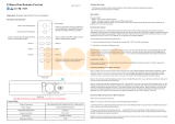
Dimensions
Waterproof Grade
868.42MHz (EU)/908.42MHz (US)/921.42MHz (ANZ)
100-240VAC, 50/60Hz
< 0.5W
0 to 40°C
8% to 80%
49.8x43x15.1mm
IP20
43.00 mm
49.81 mm
100-240VAC Power Input
4 channels switch interface
Antenna Hole
LED Indicator
Reset Button, for inclusion, exclusion, factory reset
15.15 mm
COM
K1
K2
K3
K4
L N
Push-button
Coupler

be patient to wait LED indicator to turn off.
Exclusion (Removing from a Z-Wave network)
There are two exclusion methods:
Method 1: Exclusion from the primary controller/gateway as follows:
1. Set the primary controller/gateway into exclusion mode (Please refer to your primary controllers manual on
how to set your controller into exclusion).
2. Triple press the “reset” button, the coupler will be set to exclusion mode, and waiting to be excluded.
Method 2: Factory reset the coupler will force it to be excluded from a network. (please refer to the part “Factory
Reset” of this manual)
Note: Factory reset is not recommended for exclusion, please use this procedure only if the primary
controller/gateway is missing or otherwise inoperable.
How to check whether the coupler already included to a network
Short press any button, if LED indicator flashes 3 times slowly, the coupler does not belong to any network,
otherwise, it means the coupler has already been included to a network.
If the coupler already belongs to a network, follow the exclusion process before including it in your network.
Otherwise inclusion of this device will fail.
Factory Reset
Press and hold down the “reset” button for 10 seconds, LED indicator turns on and then blinks slowly to indicate
successful factory reset.
Association
Z-Wave devices control other Z-Wave devices. The relationship between one device controlling another device
is called association. In order to control a different device, the controlling device needs to maintain a list of
devices that will receive controlling commands. These lists are called association groups and they are always
related to certain events (e.g. button pressed). In case the event happens all devices stored in the respective
association group will receive a common wireless command.
Association Groups:
Each group supports maximum 5 nodes for association, the same device can be associated with multiple
groups on the remote control simultaneously, to ensure better control experience, the remote control shall
remove the associated devices that are not under working status from association groups in time.
Function of the connected switches varies when it is configured via configuration parameter 9, the association
groups information based on different functions of the switches are as follows:
Function 1 (value of configuration parameter 9 configured as 0)
Association
Groups
Group
Name
Max
Nodes Description
Group 1 Lifeline 5
1. Send Command Class "Device Reset Locally Notification" to
associated devices of this group to report factory reset information
when factory reset the remote control by pressing and holding down
the “reset” button for 10 seconds.
2. Short press once or twice, press and hold down, release the any
of connected switch buttons K1, K2, K3, K4 to send scene activation
command to the associated devices of this group using Command
Class “Central Scene”. The actions of each switch button that
trigger central scene can be configured via parameters 5-8.
3. When push-button coupler battery power value changes, send
Command Class "Battery Report" to associated devices of this
group to report power value information.
1. Short press the switch button K1 (or K1+K2 or K1+K2+K3+K4) to
send ON/OFF command to associated devices of this group using
Command Class “Basic Set 0xff/0x00".
2. Press and hold the switch button K1 (or K1+K2 or K1+K2+K3+K4)
to send Dim command to associated devices of this group using
Command Class “Multilevel Start Level Change Up/Down". (This
Command only works when connected switch type is configured as
push button, value of configuration parameter 2 configured as 0)
Group 2 Launch 1 5
1. Short press the switch button K2 (or K3+K4) to send ON/OFF
command to associated devices of this group using Command Class
“Basic Set 0xff/0x00".
2. Press and hold the switch button K2 (or K3+K4) to send Dim
command to associated devices of this group using Command Class
“Multilevel Start Level Change Up/Down". (This Command only works
when connected switch type is configured as push button, value of
configuration parameter 2 configured as 0)
Group 3 Launch 2 5
1. Short press the switch button K3 to send ON/OFF command to
associated devices of this group using Command Class “Basic Set
0xff/0x00".
2. Press and hold the switch button K3 to send Dim command to
associated devices of this group using Command Class “Multilevel
Start Level Change Up/Down". (This Command only works when
connected switch type is configured as push button, value of
configuration parameter 2 configured as 0)
Group 4 Launch 3 5
1. Short press the switch button K4 to send ON/OFF command to
associated devices of this group using Command Class “Basic Set
0xff/0x00".
2. Press and hold the switch button K4 to send Dim command to
associated devices of this group using Command Class “Multilevel
Start Level Change Up/Down". (This Command only works when
connected switch type is configured as push button, value of
configuration parameter 2 configured as 0)
Group 5 Launch 4 5
Function 2 (value of configuration parameter 9 configured as 1)
Association
Groups
Group
Name
Max
Nodes Description
Group 1 Lifeline 5
1. Send Command Class "Device Reset Locally Notification" to
associated devices of this group to report factory reset information
when factory reset the remote control by pressing and holding down
the “reset” button for 10 seconds.
2. Short press once or twice, press and hold down, release the any
of connected switch buttons K1, K2, K3, K4 to send scene activation
command to the associated devices of this group using Command
Class “Central Scene”. The actions of each switch button that
trigger central scene can be configured via parameters 5-8.
3. When push-button coupler battery power value changes, send
Command Class "Battery Report" to associated devices of this
group to report power value information.

1. Short press the switch button K1 (or K1+K2) to send ON command
to associated devices of this group using Command Class “Basic Set
0xff".
2. Short press the switch button K2 (or K3+K4) to send OFF command
to associated devices of this group using Command Class “Basic Set
0x00".
3. Press and hold the switch button K1 (or K1+K2) to send Dim up
command to associated devices of this group using Command Class
“Multilevel Start Level Change Up". (This Command only works when
connected switch type is configured as push button, value of
configuration parameter 2 configured as 0)
4. Press and hold the switch button K2 (or K3+K4) to send Dim down
command to associated devices of this group using Command Class
“Multilevel Start Level Change Down". (This Command only works
when connected switch type is configured as push button, value of
configuration parameter 2 configured as 0)
Group 2 Launch 1 5
1. Short press the switch button K3 to send ON command to
associated devices of this group using Command Class “Basic Set
0xff".
2. Short press the switch button K4 to send OFF command to
associated devices of this group using Command Class “Basic Set
0x00".
3. Press and hold the switch button K3 to send Dim up command to
associated devices of this group using Command Class “Multilevel
Start Level Change Up". (This Command only works when connected
switch type is configured as push button, value of configuration
parameter 2 configured as 0)
4. Press and hold the switch button K4 to send Dim down command to
associated devices of this group using Command Class “Multilevel
Start Level Change Down". (This Command only works when
connected switch type is configured as push button, value of
configuration parameter 2 configured as 0)
Group 3 Launch 2 5
Function 3 (value of configuration parameter 9 configured as 2)
Association
Groups
Group
Name
Max
Nodes Description
Group 1 Lifeline 5
1. Send Command Class "Device Reset Locally Notification" to
associated devices of this group to report factory reset information
when factory reset the remote control by pressing and holding down
the “reset” button for 10 seconds.
2. Short press once or twice, press and hold down, release the any
of connected switch buttons K1, K2, K3, K4 to send scene activation
command to the associated devices of this group using Command
Class “Central Scene”. The actions of each switch button that
trigger central scene can be configured via parameters 5-8.
3. When push-button coupler battery power value changes, send
Command Class "Battery Report" to associated devices of this
group to report power value information.
1. Short press the switch button K1 to send ON command to
associated devices of this group using Command Class “Basic Set
0xff".
2. Short press the switch button K2 to send OFF command to
associated devices of this group using Command Class “Basic Set
0x00".
3. Press and hold the switch button K1 to send Dim up command to
associated devices of this group using Command Class “Multilevel
Start Level Change Up". (This Command only works when connected
switch type is configured as push button, value of configuration
parameter 2 configured as 0)
4. Press and hold the switch button K2 to send Dim down command to
associated devices of this group using Command Class “Multilevel
Start Level Change Down". (This Command only works when
connected switch type is configured as push button, value of
configuration parameter 2 configured as 0)
5. Press and hold the switch button K3 (or K1+K2) to send scene
saving command to associated devices of this group using Command
Class “Scene Actuator Configuration CC",scene ID=0x10. (This
Command only works when connected switch type is configured as
push button, value of configuration parameter 2 configured as 0)
6. Press and hold the switch button K4 (or K3+K4) to send scene
saving command to associated devices of this group using Command
Class “Scene Actuator Configuration CC",scene ID=0x20. (This
Command only works when connected switch type is configured as
push button, value of configuration parameter 2 configured as 0)
7. Short press the switch button K3 (or K1+K2) to send scene recall
command to associated devices of this group using Command Class
“Scene Activation CC",scene ID=0x10. (This Command only works
when connected switch type is configured as push button, value of
configuration parameter 2 configured as 0)
8. Short press the switch button K4 (or K3+K4) to send scene recall
command to associated devices of this group using Command Class
“Scene Activation CC",scene ID=0x20. (This Command only works
when connected switch type is configured as push button, value of
configuration parameter 2 configured as 0)
Group 2 Launch 1 5
Set and unset associations:
(Note: All association information will be cleared automatically once the push button coupler is excluded from
a network.)
Set association by operating primary controller/gateway to send association command to the coupler:
When set association from primary controller/gateway, the push button coupler shall be activated first, if it is
not activated, you should activate it manually.
The primary controller/gateway sends association command to the push button coupler using “Command Class
ASSOCIATION” or “Command Class Multi Channel Association”
Operate the device:
Function 1 (value of configuration parameter 9 configured as 0)
• Short press once, twice, press and hold down, release any of the connected switch buttons K1, K2, K3, K4 to
send scene activation command to association group 1 using Command Class “Central Scene”.

• Short press the connected switch button K1/K2/K3/K4 to send ON/OFF command to all associated devices of
Association Group 2/3/4/5 using Command Class “Basic Set 0xff/0x00".
• Press and hold the connected switch button K1/K2/K3/K4 to send light intensity increase/decrease command
to all associated devices of Association Group 2/3/4/5 using Command Class “Multilevel Start Level Change
Up/Down”. (Only works when connected switch type is configured as push button, value of configuration
parameter 2 configured as 0)
Function 2 (value of configuration parameter 9 configured as 1)
• Short press once, twice, press and hold down, release any of the connected switch buttons K1, K2, K3, K4 to
send scene activation command to association group 1 using Command Class “Central Scene”.
• Short press the switch button K1 to send ON command to all associated devices of Association Group 2
using Command Class “Basic Set 0xff", short press the switch button K2 to send OFF command to all
associated devices of Association Group 2 using Command Class “Basic Set 0x00".
• Press and hold the switch button K1 to send light intensity increase command to all associated devices of
Association Group 2 using Command Class “Multilevel Start Level Change Up”, press and hold the switch
button K2 to send light intensity decrease command to all associated devices of Association Group 2 using
Command Class “Multilevel Start Level Change Down”. (Only works when connected switch type is configured
as push button, value of configuration parameter 2 configured as 0)
• Short press the switch button K3 to send ON command to all associated devices of Association Group 3 using
Command Class “Basic Set 0xff", short press the switch button K4 to send OFF command to all associated
devices of Association Group 3 using Command Class “Basic Set 0x00"..
• Press and hold the switch button K3 to send light intensity increase command to all associated devices of
Association Group 3 using Command Class “Multilevel Start Level Change Up”, press and hold the switch
button K4 to send light intensity decrease command to all associated devices of Association Group 3 using
Command Class “Multilevel Start Level Change Down”. (Only works when connected switch type is configured
as push button, value of configuration parameter 2 configured as 0)
Function 3 (value of configuration parameter 9 configured as 2)
• Short press once, twice, press and hold down, release any of the connected switch buttons K1, K2, K3, K4 to
send scene activation command to association group 1 using Command Class “Central Scene”.
• Short press the switch button K1 to send ON command to all associated devices of Association Group 2 using
Command Class “Basic Set 0xff", short press the switch button K2 to send OFF command to all associated
devices of Association Group 2 using Command Class “Basic Set 0x00".
• Press and hold the switch button K1 to send light intensity increase command to all associated devices of
Association Group 2 using Command Class “Multilevel Start Level Change Up”, press and hold the switch
button K2 to send light intensity decrease command to all associated devices of Association Group 2 using
Command Class “Multilevel Start Level Change Down”. (Only works when connected switch type is configured
as push button, value of configuration parameter 2 configured as 0)
.
• Press and hold switch button K3/K4 button to send scene saving command to all associated devices of
Association Group 2 using Command Class "Scene Actuator Configuration", Scene ID = 0x10 / 0x20. (Only
works when connected switch type is configured as push button, value of configuration parameter 2 configured
as 0)
• Short press switch button K3/K4 button to send scene recall command to all associated devices of
Association Group 2 using Command Class "Scene Activation", Scene ID = 0x10 / 0x20. (Only works when
connected switch type is configured as push button, value of configuration parameter 2 configured as 0)
How to communicate with the device
The push button coupler is under sleepy mode for most of the time to save battery power. It can not receive
wireless command under sleepy mode. Before the gateway interacts data with the push button coupler, the
push button coupler shall be activated manually first. Press and hold down the “reset” button for 1 second to
activate the push button coupler.
Node Information Frame
The Node Information Frame is the business card of a Z-Wave device. It contains information about the device
type and the technical capabilities. The inclusion and exclusion of the device is confirmed by sending out a
Node Information Frame. Beside this it may be needed for certain network operations to send out a Node
Information Frame.
How to send out Node Information Frame:
Set the push button coupler into inclusion/exclusion mode: triple press the “reset” button, LED indicator turns
on to indicate the push button coupler has already sent out Node Information Frame, the user can repeat the
operation to set the push button coupler to quit “inclusion/exclusion mode”.
Technical Data
Power Supply
Frequency
Wireless Range
SDK
Explorer Frame Support
Device Type
Generic Device Class
Specific Device Class
Supporting Device Type
Requested security keys
Routing
FLiRS
100-240VAC, 50/60Hz
868.42 MHZ (EU)/908.42MHz (US)/921.42MHz (ANZ)
up to 100 m outside, on average up to 40 m inside buildings
7.11.1
Yes
Central Scene
WALL CONTROLLER
Not Used
Actuator
S0, S2_UNAUTHENTICATED and S2_AUTHENTICATED
No
No
Z-Wave Plus Info
Parameter
Z-Wave Plus Version
Role Type
Node Type
Installer Icon Type
User Icon Type
Value
2
Reporting Sleeping Slave (RSS)
ZWAVEPLUS
0x1600(ICON_TYPE_GENERIC_WALL_CONTROLLER)
0x1600(ICON_TYPE_GENERIC_WALL_CONTROLLER)
Manufacturer Specific
Parameter
Manufacturer ID
Product Type ID
Product ID
Value (hex)
0x330
EU=0x0400, US=0X0401, ANZ=0X0402, RU=0x0407
0x04
SUPPORTED COMMAND CLASS
Command Class Version Required Security Class
Association 2Highest granted Security Class
Association Group Info 3Highest granted Security Class
Central Scene 3Highest granted Security Class
Configuration 4Highest granted Security Class

Configuration Command Class
Size De scripti on Default ValueParameter
External switch type
0 - Push button
1 - Normal On/Off switch
2 - 3-Way switch
21 0
Duration of the Multilevel Start Level Change Up/Down
Set the duration of the Multilevel Start Level Change
Up/Down sent when pressing and holding the push button,
Valid value: 0-100
31 8
Associations in Z-Wave network Security Mode
Enable or disable to set association with association
groups in Z-Wave network Security Mode (this parameter is
only valid when the coupler is added to an encrypted
network):
0 - disable the setting for all association groups 2, 3, 4&5
1 - enable the setting for association group 2
2 - enable the setting for association group 3
The valid value of this parameter can be a combination, for
instance, when set the parameter as 1+2=3, the settings for
both association groups 2 and 3 are enabled.
4 - enable the setting for association group 4
8 - enable the setting for association group 5
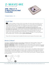
41 15 Wiring Diagram
Function of the connected switches
This parameter defines the function of the connected
switches:
0 - function 1
1 - function 2
2 - function 3
91 0
Scenes sent to the controller for button 4
This parameter defines the actions of push button 4 which
can trigger Central Scene (sent to Lifeline group):
1 - button short pressed once
2 - button short pressed twice
4 - button pressed and held
8 - button released
The valid value of this parameter can be a combination, for
instance, when set the parameter as 1+2=3, the actions of
short pressed once and short pressed twice will both work.
81 15
Notes for the diagrams:
L - terminal for live lead input
N - terminal for neutral lead input
K1, K2, K3, K4 - terminals for connecting to output terminal of the switches
COM - common terminal for connecting to input terminal of the switches
Basic Command Class mapping
Basic Command Class is not mapped to any of the supported command classes.
Firmware Update Meta Data 5Highest granted Security Class
Indicator 3Highest granted Security Class
Manufacture Specific 2Highest granted Security Class
Multi Channel Association 3Highest granted Security Class
Notification 8Highest granted Security Class
Powerlevel 1Highest granted Security Class
Version 3Highest granted Security Class
Security 0 1None
Security 2 1None
Supervision 1None
Transport Service 2None
Z-Wave Plus Info 2None
Device Reset Locally 1Highest granted Security Class
Scenes sent to the controller for button 3
This parameter defines the actions of push button 3 which
can trigger Central Scene (sent to Lifeline group):
1 - button short pressed once
2 - button short pressed twice
4 - button pressed and held
8 - button released
The valid value of this parameter can be a combination, for
instance, when set the parameter as 1+2=3, the actions of
short pressed once and short pressed twice will both work.
51 15
Scenes sent to the controller for button 2
This parameter defines the actions of push button 2 which
can trigger Central Scene (sent to Lifeline group):
1 - button short pressed once
2 - button short pressed twice
4 - button pressed and held
8 - button released
The valid value of this parameter can be a combination, for
instance, when set the parameter as 1+2=3, the actions of
short pressed once and short pressed twice will both work.
61 15
71 15
Scenes sent to the controller for button 1
This parameter defines the actions of push button 1 which
can trigger Central Scene (sent to Lifeline group):
1 - button short pressed once
2 - button short pressed twice
4 - button pressed and held
8 - button released
The valid value of this parameter can be a combination, for
instance, when set the parameter as 1+2=3, the actions of
short pressed once and short pressed twice will both work.

L
N
(2) Normal On/Off Switch Connection
L
N
(3) 3-Way Switch Connection
3-Way Switch (SPDT)
3-Way Switch (SPDT)
PUSH
Button 2
PUSH
Button 3
PUSH
Button 1
PUSH
Button 4
L
N
(1) Push Button Switch Connection
COM
K1
K2
K3
K4
L N
Push-button
Coupler
COM
K1
K2
K3
K4
L N
Push-button
Coupler
COM
K1
K2
K3
K4
L N
Push-button
Coupler
/