Page is loading ...
311211M
ENG
Instructions - Parts List
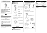
High-Flo
®
Pumps
Designed for low pressure, medium volume circulation of finishing materials.
Do not use with caustics, acids, abrasive line strippers, and other similar fluids.
For professional use only.
Patent Pending
Important Safety Instructions
Read all warnings and instructions in this manual.
Save these instructions.
See page 2 for Table of Contents and page 3 for
List of Models.
See page 25 for Maximum Working Pressures.
Related Manuals
Part No. Description
311238 NXT Air Motor manual
308330 Viscount I Plus Hydraulic Motor manual
311690 High-Flo Lower manual
308048 Viscount II Hydraulic Motor manual
TI8354a
NXT Air-Powered
Pump Shown
II 2 G

2 311211M
Contents
Models . . . . . . . . . . . . . . . . . . . . . . . . . . . . . . . . . . . 3
NXT Air-Powered Pumps . . . . . . . . . . . . . . . . . . 3
Viscount I Plus Hydraulic-Powered Pumps . . . . . 3
Viscount II Hydraulic Powered Pumps . . . . . . . . 4
Warnings . . . . . . . . . . . . . . . . . . . . . . . . . . . . . . . . . 5
Installation . . . . . . . . . . . . . . . . . . . . . . . . . . . . . . . . 7
Grounding . . . . . . . . . . . . . . . . . . . . . . . . . . . . . . 7
Accessories . . . . . . . . . . . . . . . . . . . . . . . . . . . . . 8
Air-Powered Pumps . . . . . . . . . . . . . . . . . . . 8
Hydraulic-Powered Pumps . . . . . . . . . . . . . . 8
All Pumps . . . . . . . . . . . . . . . . . . . . . . . . . . . 9
Air-Powered Pumps Typical Installation . . . . . . 10
Hydraulic-Powered Pumps Typical Installation . 11
Operation . . . . . . . . . . . . . . . . . . . . . . . . . . . . . . . . 12
Pressure Relief Procedure . . . . . . . . . . . . . . . . 12
Flush Before Using Equipment . . . . . . . . . . . . . 12
Trigger Lock . . . . . . . . . . . . . . . . . . . . . . . . . . . . 12
Pump Operation . . . . . . . . . . . . . . . . . . . . . . . . 12
Stop the Pump at the Bottom of Its Stroke . . . . 12
Maintenance . . . . . . . . . . . . . . . . . . . . . . . . . . . . . . 13
Preventive Maintenance Schedule . . . . . . . . . . 13
Flushing . . . . . . . . . . . . . . . . . . . . . . . . . . . 13
Air Line Filter . . . . . . . . . . . . . . . . . . . . . . . 13
Hydraulic Power Supply Check . . . . . . . . . . 13
Mix Tank Volume . . . . . . . . . . . . . . . . . . . . . 13
Packing Nut Tightness . . . . . . . . . . . . . . . . 13
Excessive Leaking at Throat . . . . . . . . . . . 13
Troubleshooting . . . . . . . . . . . . . . . . . . . . . . . . . . . 14
Repair . . . . . . . . . . . . . . . . . . . . . . . . . . . . . . . . . . . 15
Disconnect the Lower . . . . . . . . . . . . . . . . . . . . 15
Reconnect the Lower . . . . . . . . . . . . . . . . . . . . . 15
Reassemble the Coupling Rod and Tie Rods
to the Motor . . . . . . . . . . . . . . . . . . . . . . . . . 16
Parts . . . . . . . . . . . . . . . . . . . . . . . . . . . . . . . . . . . . 18
NXT Pumps . . . . . . . . . . . . . . . . . . . . . . . . . . . . 18
Common Parts . . . . . . . . . . . . . . . . . . . . . . 18
Parts That Vary by Model . . . . . . . . . . . . . . 19
Viscount I Plus Pumps . . . . . . . . . . . . . . . . . . . . 21
Common Parts . . . . . . . . . . . . . . . . . . . . . . 21
Parts That Vary by Model . . . . . . . . . . . . . . 21
Viscount II 460 Pumps . . . . . . . . . . . . . . . . . . . . 22
Common Parts . . . . . . . . . . . . . . . . . . . . . . 22
Parts That Vary by Model . . . . . . . . . . . . . . 22
Dimensions . . . . . . . . . . . . . . . . . . . . . . . . . . . . . . . 23
Pump Mounting Hole Diagram . . . . . . . . . . . . . . . 24
Technical Data . . . . . . . . . . . . . . . . . . . . . . . . . . . . 25
NXT . . . . . . . . . . . . . . . . . . . . . . . . . . . . . . . . . . 25
Viscount I Plus Pumps . . . . . . . . . . . . . . . . . . . . 25
Viscount II Pumps . . . . . . . . . . . . . . . . . . . . . . . 25
Performance Charts . . . . . . . . . . . . . . . . . . . . . . . . 26
Air-Powered Pumps . . . . . . . . . . . . . . . . . . . . . . 26
Hydraulic Powered Pumps . . . . . . . . . . . . . . . . 28
Viscount II 460 Pumps . . . . . . . . . . . . . . . . . . . . 29
Graco Standard Warranty . . . . . . . . . . . . . . . . . . . 30
Graco Information . . . . . . . . . . . . . . . . . . . . . . . . . 30

Models
311211M 3
Models
NXT Air-Powered Pumps
Your model number is marked on the pump identification plate located toward the rear of the air motor. To determine
the model number of your pump from the following matrix, select the six digits which describe your pump. The first
digit is always J for circulation pumps. The remaining five digits define the construction. For example, a circulation
pump with carbon steel construction, a 2.0:1 ratio, low noise exhaust, no communication option, npt fittings, and
chrome rod and cylinder is model number JC20L1. To order replacement parts, see page 18.
J C20 L1
First
Digit
Second Digit Third and Fourth Digit Fifth Digit Sixth Digit
Material
Motor
Size
Lower
Size
Maximum
Fluid
Pressure
psi (MPa, bar) Exhaust
Communi-
cation Fittings
Rod and
Cylinder
J
(all
circulation
pumps)
C Carbon Steel 20 2200 2000 200 (1.4, 14.0) L Low Noise none 1 npt Chromex/
Chrome
S Stainless Steel 30 2200 1500 300 (2.1, 21.0) M Low Noise
DataTrak
™
2 npt Chromex/
MaxLife
35 3400 2000 340 (2.3, 23.0) R Remote none 3 bspp* Chromex/
Chrome
40 2200 1000 400 (2.8, 28.0) S Remote
DataTrak
™
4 bspp* Chromex/
MaxLife
45 3400 1500 460 (3.2, 32.0)
5 tri-
clamp
Chromex/
Chrome
6 tri-
clamp
Chromex/
MaxLife
XX = X.X:1 ratio 7 npt Chromex/
Nitride

Models
4 311211M
Viscount I Plus Hydraulic-Powered Pumps
*BSPP models require inlet and outlet seals to perform optimally. See Accessories, page 9.
Viscount II Hydraulic Powered Pumps
*BSPP models require inlet and outlet seals to perform optimally. See Accessories, page 9.
Model No. Series
Maximum Pump
Working Pressure
psi (MPa, bar)
Connection
Style Material
Rod
Material
Cylinder
Material
High-Flo Lower
(see manual 311690)
253642 A 300 (2.1, 21) npt sst Chromex Chrome 253033
253643 A 225 (1.6, 16) npt sst Chromex Chrome 253034
24E787 A 300 (2.1, 21) npt sst Chromex Chrome 24E783
24E788 A 225 (1.6, 16) npt sst Chromex Chrome 24E784
253644 A 300 (2.1, 21) npt sst Chromex MaxLife 253568
253645 A 225 (1.6, 16) npt sst Chromex MaxLife 253569
253646 A 300 (2.1, 21) npt cst Chromex Nitride 253061
253647 A 225 (1.6, 16) npt cst Chromex Nitride 253062
253648 A 300 (2.1, 21) bspp* sst Chromex Chrome 253423
253649 A 225 (1.6, 16) bspp* sst Chromex Chrome 253085
253650 A 300 (2.1, 21) bspp* sst Chromex MaxLife 253398
253651 A 225 (1.6, 16) bspp* sst Chromex MaxLife 253397
253652 A 300 (2.1, 21) tri-clamp sst Chromex Chrome 253520
253653 A 225 (1.6, 16) tri-clamp sst Chromex Chrome 253521
253654 A 300 (2.1, 21) tri-clamp sst Chromex MaxLife 253523
253655 A 225 (1.6, 16) tri-clamp sst Chromex MaxLife 253524
Model No. Series
Maximum Pump
Working Pressure
psi (MPa, bar)
Connection
Style Material
Rod
Material
Cylinder
Material
High-Flo Lower
(see manual 311690)
247355 A 460 (3.2, 32) npt sst Chromex Chrome 253035
24E786 A 460 (3.2, 32) npt sst Chromex Chrome 24E785
247356 A 460 (3.2, 32) npt cs Chromex Chrome 253063
247357 A 460 (3.2, 32) bspp* sst Chromex Chrome 253086
247358 A 460 (3.2, 32) bspp* sst Chromex MaxLife 253396
247359 A 460 (3.2, 32) tri-clamp sst Chromex Chrome 253522
247360 A 460 (3.2, 32) tri-clamp sst Chromex MaxLife 253525
247361 A 460 (3.2, 32) npt sst Chromex MaxLife 253570

Warnings
311211M 5
Warnings
The following warnings are for the setup, use, grounding, maintenance, and repair of this equipment. The exclama-
tion point symbol alerts you to a general warning and the hazard symbol refers to procedure-specific risk. Refer back
to these warnings. Additional, product-specific warnings may be found throughout the body of this manual where
applicable.
WARNING
FIRE AND EXPLOSION HAZARD
Flammable fumes, such as solvent and paint fumes, in work area can ignite or explode. To help prevent
fire and explosion:
• Use equipment only in well ventilated area.
• Eliminate all ignition sources; such as pilot lights, cigarettes, portable electric lamps, and plastic drop
cloths (potential static arc).
• Keep work area free of debris, including solvent, rags and gasoline.
• Do not plug or unplug power cords, or turn power or light switches on or off when flammable fumes
are present.
• Ground all equipment in the work area. See Grounding instructions.
• Use only grounded hoses.
• Hold gun firmly to side of grounded pail when triggering into pail.
• If there is static sparking or you feel a shock, stop operation immediately. Do not use equipment
until you identify and correct the problem.
• Keep a working fire extinguisher in the work area.
PRESSURIZED EQUIPMENT HAZARD
Fluid from the gun/dispense valve, leaks, or ruptured components can splash in the eyes or on skin and
cause serious injury.
• Follow Pressure Relief Procedure in this manual, when you stop spraying and before cleaning,
checking, or servicing equipment.
• Tighten all fluid connections before operating the equipment.
• Check hoses, tubes, and couplings daily. Replace worn or damaged parts immediately.
EQUIPMENT MISUSE HAZARD
Misuse can cause death or serious injury.
• Do not operate the unit when fatigued or under the influence of drugs or alcohol.
• Do not exceed the maximum working pressure or temperature rating of the lowest rated system
component. See Technical Data in all equipment manuals.
• Use fluids and solvents that are compatible with equipment wetted parts. See Technical Data in all
equipment manuals. Read fluid and solvent manufacturer’s warnings. For complete information
about your material, request MSDS forms from distributor or retailer.
• Check equipment daily. Repair or replace worn or damaged parts immediately with genuine manu-
facturer’s replacement parts only.
• Do not alter or modify equipment.
• Use equipment only for its intended purpose. Call your distributor for information.
• Route hoses and cables away from traffic areas, sharp edges, moving parts, and hot surfaces.
• Do not kink or over bend hoses or use hoses to pull equipment.
• Keep children and animals away from work area.
• Comply with all applicable safety regulations.

Warnings
6 311211M
MOVING PARTS HAZARD
Moving parts can pinch or amputate fingers and other body parts.
• Keep clear of moving parts.
• Do not operate equipment with protective guards or covers removed.
• Pressurized equipment can start without warning. Before checking, moving, or servicing equipment,
follow the Pressure Relief Procedure in this manual. Disconnect power or air supply.
TOXIC FLUID OR FUMES HAZARD
Toxic fluids or fumes can cause serious injury or death if splashed in the eyes or on skin, inhaled, or
swallowed.
• Read MSDS’s to know the specific hazards of the fluids you are using.
• Store hazardous fluid in approved containers, and dispose of it according to applicable guidelines.
• Always wear impervious gloves when spraying or cleaning equipment.
PERSONAL PROTECTIVE EQUIPMENT
You must wear appropriate protective equipment when operating, servicing, or when in the operating
area of the equipment to help protect you from serious injury, including eye injury, inhalation of toxic
fumes, burns, and hearing loss. This equipment includes but is not limited to:
• Protective eyewear
• Clothing and respirator as recommended by the fluid and solvent manufacturer
•Gloves
• Hearing protection
WARNING

Installation
311211M 7
Installation
Grounding
The equipment must be grounded. Grounding reduces
the risk of static and electric shock by providing an
escape wire for the electrical current due to static build
up or in the event of a short circuit.
Pump: Use a ground screw (Z) and lockwasher on the
motor to attach ground wire 244524 (Y). Tighten the
screw securely. Connect the other end of the ground
wire to a true earth ground. See F
IG. 1.
Air and fluid hoses: use only electrically conductive
hoses with a maximum of 500 ft. (150 m) combined
hose length to ensure grounding continuity. Check the
electrical resistance of hoses. If total resistance to
ground exceeds 29 megohms, replace hose immedi-
ately.
Air compressor: follow manufacturer’s recommenda-
tions.
Hydraulic power supply: follow manufacturer’s recom-
mendations.
Surge tank: use a ground wire and clamp.
Spray gun: ground through a connection to a properly
grounded fluid hose and pump.
Fluid supply container: follow local code.
Object being sprayed: follow local code.
Solvent pails used when flushing: follow local code.
Use only conductive metal pails, placed on a grounded
surface. Do not place the pail on a nonconductive sur-
face, such as paper or cardboard, which interrupts
grounding continuity.
To maintain grounding continuity when flushing or
relieving pressure: hold metal part of the spray gun
firmly to the side of a grounded metal pail, then trigger
the gun.
FIG. 1
TI8250a
Z Y

Installation
8 311211M
Accessories
Install the following accessories in the order shown in
F
IG. 2 and FIG. 3, using adapters as necessary.
Air-Powered Pumps
For typical installation, see FIG. 2 on page 10.
Air Line
• Bleed-type master air valve (M): required in your
system to relieve air trapped between it and the air
motor when the valve is closed.
Be sure the valve is easily accessible from the pump
and located downstream from the air regulator. Be sure
the air bleed hole points away from the operator.
• Pump air regulator (L): to control pump speed and
outlet pressure. Locate close to the pump.
• Air line filter (K): removes harmful dirt and mois-
ture from compressed air supply.
• Second bleed-type air valve (M): isolates air line
accessories for servicing. Locate upstream from all
other air line accessories.
Hydraulic-Powered Pumps
For typical installation, see FIG. 3 on page 11.
Hydraulic Power Supply
Be sure the power supply can provide sufficient power to
the motor. Be sure the power supply is equipped with a
suction filter to the hydraulic pump.
Hydraulic Supply Line
• Supply line shutoff valve (S): isolates the motor
when servicing the system. See F
IG. 3.
• Hydraulic fluid pressure gauge (P): monitors the
hydraulic oil pressure to the motor to avoid over-
pressurizing the motor or lower.
• Pressure- and temperature-compensated flow
control valve (T): prevents the motor from running
too fast, which can damage it.
• Pressure reducing valve (N), which has a drain
line (M) running to the return line (K): controls the
hydraulic pressure to the motor.
Accessory Air Control Kits are available for the NXT
Air Motor. The kits include a master air valve, air
regulator, and filter. Order the kits separately. See
manual 311239 for more information.
Trapped air can cause the pump to cycle unexpectedly,
which could result in serious injury from splashing or
moving parts.
The air motor is rated to 100 psi (0.7 MPa, 7.0 bar). If
you will apply more than 100 psi (0.7 MPa, 7.0 bar) to
the system, install a safety relief valve between the
bleed-type master air valve and the air motor.
CAUTION
The hydraulic power supply must be kept clean at all
to avoid damage to the motor and hydraulic power
supply.
1. Blow out hydraulic lines with air and flush thor-
oughly before connection to the motor.
2. Plug hydraulic inlets, outlets, and line ends when
disconnecting them for any reason.
• For Viscount I Plus motors, the hydraulic inlet
on the motor is 3/4 in., 37° flare. Use a mini-
mum 1/2 in. (13 mm) ID hydraulic supply line
(K).
• For Viscount II motors, use a minimum 13 mm
(1/2 in.) ID supply line supply line (K). The
motor has a 3/4 npt(f) hydraulic oil supply fit-
ting.

Installation
311211M 9
Hydraulic Return Line
• Return line shutoff valve (R): isolates the motor
when servicing the system.
• Return fluid filter (J): removes residue from the
hydraulic fluid to help keep the system running
smoothly (10 micron size).
All Pumps
Fluid Line
• Fluid filter: with a 60 mesh (250 micron) stainless
steel element to filter particles from the fluid as it
leaves the pump.
• Fluid drain valve (U): required in your system, to
relieve fluid pressure in the hose and gun.
• Fluid shutoff valve (D): shuts off fluid flow.
• Fluid pressure regulator: for more precise adjust-
ment of the fluid pressure.
• Gun or valve: to dispense fluid.
• Fluid line swivel: for easier gun movement.
• Suction kit: enables the pump to draw fluid from a
container.
• Inlet and outlet seals: prevent leakage in BSPP
models. Order 193423 for 1-1/2 in. inlet seal and
193422 for 1-1/4 in. outlet seal.
• For Viscount I Plus motors, the hydraulic outlet
on the motor is 7/8 in., 37° flare. Use a mini-
mum 5/8 in. (16 mm) ID hydraulic return line
(J).
• For Viscount II motors, use a minimum 22 mm
(7/8 in.) ID return line (J). The motor has a 1 in.
npt(f) hydraulic oil return fitting.
CAUTION
To avoid damage to the pump, never use the return
line shutoff valve to control the hydraulic flow. Do not
install any flow control devices on the hydraulic return
line.

Installation
10 311211M
Air-Powered Pumps Typical Installation
Key:
A Mix Tank
B Pump Stand
C Fluid Supply Line; 1-1/2 in. (38 mm) minimum diameter
D Fluid Shutoff Valve
E Fluid Line; 1 in. (25 mm) minimum diameter
F Surge Tank Stand
G Surge Tank
H Ground Wire (required, see page 7 for installation)
J Air Supply Line
K Air Line Filter
L Air Regulator and Gauge
M Bleed-Type Master Air Valve (required)
N Fluid Drain Valve (required)
FIG. 2: Typical Installation
TI8398a
A
B
F
G
N
DD
J
M
M
KL
N
D
C
E

Installation
311211M 11
Hydraulic-Powered Pumps Typical Installation
Key:
AMix Tank
B Pump Stand
C Fluid Supply Line; 1-1/2 in. (38 mm) minimum diameter
D Fluid Shutoff Valve
E Fluid Line; 1 in. (25 mm) minimum diameter
F Surge Tank Stand
G Surge Tank
J 10 Micron Return Filter
K Hydraulic Return Line; 5/8 in. (16 mm) minimum diameter
L Hydraulic Supply Line; 1/2 in. (13 mm) minimum diameter
MDrain Line
N Pressure Reducing Valve
P Hydraulic Pressure Gauge
R Return Line Shutoff Valve
S Supply Line Shutoff Valve
T Flow Control Valve
U Fluid Drain Valve (required)
Y Ground Wire (required see page 7 for installation)
FIG. 3: Typical Installation
TI8399a
K
L
F
A
U
E
B
D
G
D
E
U
D
R
N
P
S
J
C
M
T

Operation
12 311211M
Operation
Pressure Relief Procedure
1. Engage trigger lock.
2. Air-Powered Pumps only: Close the bleed-type
master air valve.
Hydraulic-Powered Pumps only: Shut off the
hydraulic supply line valve (S) first, then the return
line valve (R).
3. Disengage the trigger lock.
4. Hold a metal part of the gun firmly to a grounded
metal pail. Trigger the gun to relieve pressure.
5. Engage the trigger lock.
6. Open all fluid drain valves in the system, having
waste containers ready to catch drainage. Leave the
drain valves open until you are ready to spray again.
7. If you suspect the spray tip or hose is clogged or
that pressure has not been fully relieved after follow-
ing the steps above, VERY SLOWLY loosen the tip
guard retaining nut or hose end coupling to relieve
pressure gradually, then loosen completely. Clear
hose or tip obstruction.
Flush Before Using Equipment
The equipment was tested with lightweight oil, which is
left in the fluid passages to protect parts. To avoid con-
taminating your fluid with oil, flush the equipment with a
compatible solvent before using the equipment. See
Flushing, page 13.
Trigger Lock
Always engage the trigger lock when you stop spraying
to prevent the gun from being triggered accidentally by
hand or if dropped or bumped.
Pump Operation
Stop the Pump at the Bottom of
Its Stroke
Relieve the pressure when you stop the pump for any
reason. Stop the pump on the downstroke, before the air
motor changes over.
CAUTION
Hydraulic-Powered Pumps only: When shutting down
the hydraulic system, always shut off the hydraulic
supply line shutoff valve (S) first, and then the return
line shutoff valve (R) to prevent overpressurizing the
motor or its seals. When starting the hydraulic sys-
tem, open the return line shutoff valve first.
• In a circulation system, the pump operates con-
tinuously until the power supply is shut off.
CAUTION
Do not allow the pump to run quickly for a long period
of time as this may damage the packings.
• In a direct-supply system, the pump starts
when the gun is opened, and stops when the
gun is closed.
• Perform a stall test periodically to ensure the
piston seal is in good working condition and
prevent system overpressurization:
• Close the fluid shutoff valve (D) closest to the
pump on the downstroke and be sure that the
pump stalls. Open the fluid shutoff valve to
restart the pump. Close the fluid shutoff valve
(D) closest to the pump on the upstroke and be
sure that the pump stalls.
CAUTION
Failure to stop the pump at the bottom of its stroke
allows fluid to dry on the piston rod, which can cause
damage to the throat packings when the pump is
restarted.
Hydraulic-Powered Pumps only: Always shut off the
supply line shutoff valve (S) first, and then the
return line shutoff valve (R). This is to prevent over-
pressurizing the motor or its seals.

Maintenance
311211M 13
Maintenance
Preventive Maintenance
Schedule
The operating conditions of your particular system
determine how often maintenance is required. Establish
a preventive maintenance schedule by recording when
and what kind of maintenance is needed, and then
determine a regular schedule for checking your system.
Your maintenance schedule should include the follow-
ing:
Flushing
Air Line Filter
Drain and clean as necessary.
Hydraulic Power Supply Check
Carefully follow the hydraulic power supply manufac-
turer's recommendations on reservoir and filter cleaning,
and periodic changes of hydraulic fluid.
Mix Tank Volume
Don't let the mix tank run dry. When the tank is empty,
the pump demands more power as it tries to suck in
some fluid. This causes the pump to run too fast, which
can seriously damage the pump.
Packing Nut Tightness
Check the packing nut (21) tightness every few days at
startup and then weekly throughout the life of the throat
seal. The packing nut should be tight enough to stop
leakage, but no tighter. See F
IG. 4.
To check the adjustment of the packing nut, stop the
pump and relieve fluid pressure. Loosen the packing nut
until it turns freely. Tighten the nut firmly and then turn
the nut another 1/4 turn. If you have a torque wrench,
tighten the packing nut to 30 ft-lb (40 N•m), then back off
and re-tighten to 15-20 ft-lb (20-27 N•m).
Excessive Leaking at Throat
If you see excessive leaking at the throat, tighten the
packing nut (21), see F
IG. 4. If this does not fix the prob-
lem, replace the throat packings, piston rod, or both See
manual 311690.
• Flush before shutting down the system for an
extended period of time.
• Flush before repairing the pump, if possible.
• Flush before fluid can dry out, settle, or set up
in the equipment.
F
IG. 4
NXT Air-Powered
Pump Shown
TI8354a
1
Torque to 15-20 ft-lb (20-27 N•m).
1
packing nut

Troubleshooting
14 311211M
Troubleshooting
1. Relieve the pressure.
2. Check all possible problems and solutions before
disassembling pump.
PROBLEM CAUSE SOLUTION
Pump output low on both strokes. Restricted air or hydraulic supply lines. Clear any obstructions; be sure all shutoff
valve are open; increase pressure, but do
not exceed maximum working pressure.
Exhausted fluid supply. Refill and reprime pump.
Clogged fluid outlet line, valves, etc. Clear.
Worn piston packing. Replace. See lower manual 311690.
Pump output low on only one stroke. Held open or worn ball check valves. Check and repair.
Worn piston packings. Replace. See lower manual 311690.
Pump operates erratically. Exhausted fluid supply. Refill and reprime pump.
Held open or worn ball check valves. Check and repair.
Worn piston packing. Replace. See lower manual 311690.
Excessive hydraulic fluid supply pressure
to Viscount motor.
See Viscount I Plus motor manual
308330 or Viscount II manual 308048.
Pump will not operate. Restricted air or hydraulic supply lines. Clear any obstructions; be sure all shut
off valves are open; increase pressure,
but do not exceed maximum working
pressure.
Exhausted fluid supply. Refill and reprime pump.
Clogged fluid outlet line, valves, etc. Clear.
Damaged air motor or hydraulic motor. See air motor manual 311238 or hydrau-
lic motor manual 308330 or 308048.
Fluid dried on piston rod. Disassemble and clean pump. See lower
manual 311690. In future, stop pump at
bottom of stroke.
Pump will not prime Suction line clogged. Clear. Flush more frequently.
Held open or worn ball check valves. Check and repair.
Piston assembled with wrong nut. Use only the large, round, special nut.
Excessive throat leakage. Worn piston rod or throat packings. Replace. See lower manual 311690.
Pump will not stall when fluid is shut off. Warn ball check valves. Check and repair.
Worn piston packing. Replace. See lower manual 311690.

Repair
311211M 15
Repair
Disconnect the Lower
To service the lower, follow the procedure on this page,
and disassemble the pump as described in manual
311690. To disconnect pump from an electric circulation
assembly, EPXXXX, see manual 311594.
1. Relieve the pressure, see Pressure Relief Proce-
dure page 12.
2. Disconnect the hoses from the lower and plug the
ends to prevent fluid contamination.
3. Loosen the coupling nut (K) and remove the collars
(G). Remove the coupling nut from the piston rod
(H). Unscrew the locknuts (B) from the tie rods (C).
Pull the lower (D) off the motor (E). See F
IG. 5 and
F
IG. 6.
Reconnect the Lower
1. Assemble the coupling nut (K) to the piston rod (H).
2. Orient the lower (D) to the motor (E). Position the
lower on the tie rods (C). Lubricate the threads of
the tie rods. Screw the tie rod locknuts (B) onto the
tie rods. Tighten the locknuts and torque to 50-55
ft-lb (68-75 N•m).
3. Insert the collars (G) into the coupling nut (K).
Tighten the coupling nut onto the piston rod (H) and
torque to 90-100 ft-lb (122-135 N•m).
4. Flush and test the pump before reinstalling it in the
system. Connect hoses and flush the pump. While it
is pressurized, check for smooth operation and
leaks. Adjust or repair as necessary before reinstall-
ing in the system. Reconnect the pump ground wire
before operating.
• To service the lower, see manual 311690.
• To service the air motor, see manual 311238.
• To service the Viscount I Plus hydraulic motor,
see manual 308330.
• To service the Viscount II hydraulic motor, see
manual 308048.
In stand or wall-mounted installations, you do not
have to remove the entire pump from its mounting.
If the coupling rod (F) and tie rods (C) have been
disassembled from the motor, see Reassemble the
Coupling Rod and Tie Rods to the Motor on page
16.
FIG. 5
NXT Pump
Shown
TI8394b
1
Torque to 90-100 ft-lb
(122-135 N•m).
Torque to 50-60 ft-lb
(68-81 N•m).
Apply lubricant.
1
2
3
C
K
H
2
E
B
3
2
G
F
D
3

Repair
16 311211M
Reassemble the Coupling Rod
and Tie Rods to the Motor
1. Loosen, but do not remove, the screws holding the
adapter plate (J) to the motor (E), on Viscount I Plus
pumps. See F
IG. 6. For Viscount II pumps, torque
screw (N) to 50-55 ft-lb (68-75 N•m) into motor (E).
2. Screw the tie rods (C) into the adapter plate (J) and
torque to 50-55 ft-lb (68-75 N•m). On Viscount I Plus
pumps, the tie rods will engage threaded holes in
the base of the motor. Viscount II pumps will engage
into the adapter plate (J).
3. Fill the cavity in the bottom of the motor shaft with
grease. Screw the coupling rod (F) into the motor
shaft until the pin holes align. Install the pin (A) in
the first hole from the end of the coupling. On Vis-
count II pumps, torque the coupling nut (M) into the
motor shaft.
4. Align the lower (D) with the tie rods (C) and loosely
install the tie rod locknuts (B).
5. Insert the collars (G) and screw the coupling nut (K)
onto the coupling rod (F) and torque to 90-100 ft-lb
(122-135 N•m).
6. For Viscount I Plus pumps, torque the holding the
adapter plate (J) to the motor (E) to 15-17 ft-lb
(20-23 N•m). For Viscount I Plus and Viscount II
pumps, torque the tie rod locknuts (B) to 50-55 ft-lb
(68-75 N•m).
F
IG. 6
Use this procedure only if the coupling rod (F) and
tie rods (C) have been disassembled from the
motor, to ensure proper alignment of the motor
shaft to the piston rod.
Viscount I Plus
Pump Shown
TI7674b
Torque to 90-100 ft-lb
(122-135 N•m).
Torque to 50-55 ft-lb
(68-75 N•m).
Lubricate threads.
1
2
3
1
J
C
G
K
3
2
E
B
A
H
F
D
FIG. 7
Viscount II 460
Pump Shown
TI10466a
3
1
2
Torque to 90-100 ft-lb
(122-135 N•m).
Torque to 50-55 ft-lb
(68-75 N•m).
Lubricate threads.
1
2
3
E
F
G
K
H
D
B
C
J
M
N
2
3

Repair
311211M 17

Parts
18 311211M
Parts
NXT Pumps
Common Parts
101
105
104
102
106
107
103
TI8394b
108
Ref.
No. Description Part No. Qty.
101 MOTOR, NXT, see manual 311238 see table,
page 19
1
102 LOWER, High-Flo, see manual 311690 see table,
page 19
1
103 NUT, coupling 184059 1
104 COLLAR, coupling 184128 2
105 ADAPTER, coupling 15H369 1
106 TIE ROD, 14.25 in. (362 mm) between
shoulders
15G924 3
107 NUT, lock, hex; 9/16-12 unc 108683 3
108 COVER, moisture 247362 1

Parts
311211M 19
Parts That Vary by Model
101 102
Air-Powered
Pump
(see page 3)
NXT Air Motor
(see manual 311238)
High-Flo Lower
(see manual 311690)
JC20L1 N22LN0 253063
JC20M1 N22LT0 253063
JC30L7 N22LN0 253062
JC30M7 N22LT0 253062
JC35L1 N34LN0 253063
JC35M1 N34LT0 253063
JC40L7 N22LN0 253061
JC40M7 N22LT0 253061
JC45L7 N34LN0 253062
JC45M7 N34LT0 253062
JS20L1 N22LN0 253035
JS20L2 N22LN0 253570
JS20L3 N22LN0 253086
JS20L4 N22LN0 253396
JS20L5 N22LN0 253522
JS20L6 N22LN0 253525
JS20M1 N22LT0 253035
JS20M2 N22LT0 253570
JS20M3 N22LT0 253086
JS20M4 N22LT0 253396
JS20M5 N22LT0 253522
JS20M6 N22LT0 253525
JS20R1 N22RN0 253035
JS20R2 N22RN0 253570
JS20R3 N22RN0 253086
JS20R4 N22RN0 253396
JS20R5 N22RN0 253522
JS20R6 N22RN0 253525
JS20S1 N22RT0 253035
JS20S2 N22RT0 253570
JS20S3 N22RT0 253086
JS20S4 N22RT0 253396
JS20S5 N22RT0 253522
JS20S6 N22RT0 253525
JS30L1 N22LN0 253034
JS30L2 N22LN0 253569
JS30L3 N22LN0 253085
JS30L4 N22LN0 253397
JS30L5 N22LN0 253521
JS30L6 N22LN0 253524
JS30M1 N22LT0 253034
JS30M2 N22LT0 253569
JS30M3 N22LT0 253085
JS30M4 N22LT0 253397
JS30M5 N22LT0 253521
JS30M6 N22LT0 253524
JS30R1 N22RN0 253034
JS30R2 N22RN0 253569
JS30R3 N22RN0 253085
JS30R4 N22RN0 253397
JS30R5 N22RN0 253521
JS30R6 N22RN0 253524
JS30S1 N22RT0 253034
JS30S2 N22RT0 253569
JS30S3 N22RT0 253085
JS30S4 N22RT0 253397
JS30S5 N22RT0 253521
JS30S6 N22RT0 253524
JS35L1 N34LN0 253035
JS35L2 N34LN0 253570
JS35L3 N34LN0 253086
JS35L4 N34LN0 253396
JS35L5 N34LN0 253522
JS35L6 N34LN0 253525
JS35M1 N34LT0 253035
JS35M2 N34LT0 253570
JS35M3 N34LT0 253086
JS35M4 N34LT0 253396
JS35M5 N34LT0 253522
JS35M6 N34LT0 253525
JS35R1 N34RN0 253035
JS35R2 N34RN0 253570
JS35R3 N34RN0 253086
JS35R4 N34RN0 253396
JS35R5 N34RN0 253522
JS35R6 N34RN0 253525
JS35S1 N34RT0 253035
JS35S2 N34RT0 253570
JS35S3 N34RT0 253086
JS35S4 N34RT0 253396
JS35S5 N34RT0 253522
JS35S6 N34RT0 253525
JS40L1 N22LN0 253033
JS40L2 N22LN0 253568
JS40L3 N22LN0 253423
JS40L4 N22LN0 253398
JS40L5 N22LN0 253520
JS40L6 N22LN0 253523
JS40M1 N22LT0 253033
JS40M2 N22LT0 253568
JS40M3 N22LT0 253423
JS40M4 N22LT0 253398
JS40M5 N22LT0 253520
JS40M6 N22LT0 253523
JS40R1 N22RN0 253033
JS40R2 N22RN0 253568
JS40R3 N22RN0 253423
JS40R4 N22RN0 253398
JS40R5 N22RN0 253520
JS40R6 N22RN0 253523
JS40S1 N22RT0 253033
JS40S2 N22RT0 253568
JS40S3 N22RT0 253423
JS40S4 N22RT0 253398
JS40S5 N22RT0 253520
JS40S6 N22RT0 253523
JS45L1 N34LN0 253034
JS45L2 N34LN0 253569
JS45L3 N34LN0 253085
JS45L4 N34LN0 253397
JS45L5 N34LN0 253521
JS45L6 N34LN0 253524
JS45M1 N34LT0 253034
JS45M2 N34LT0 253569
JS45M3 N34LT0 253085
JS45M4 N34LT0 253397
JS45M5 N34LT0 253521
JS45M6 N34LT0 253524
101 102
Air-Powered
Pump
(see page 3)
NXT Air Motor
(see manual 311238)
High-Flo Lower
(see manual 311690)

Parts
20 311211M
JS45R1 N34RN0 253034
JS45R2 N34RN0 253569
JS45R3 N34RN0 253085
JS45R4 N34RN0 253397
JS45R5 N34RN0 253521
JS45R6 N34RN0 253524
JS45S1 N34RT0 253034
JS45S2 N34RT0 253569
JS45S3 N34RT0 253085
JS45S4 N34RT0 253397
JS45S5 N34RT0 253521
JS45S6 N34RT0 253524
101 102
Air-Powered
Pump
(see page 3)
NXT Air Motor
(see manual 311238)
High-Flo Lower
(see manual 311690)
/