TM
Inside:
- Introduction
- Player & Server Installation
- mediaControl Setup
- Using mediaControl
- mediaControl Tools
TM
create. move. play. save.
purely digital
TM
Operations Manual
edje 4111 HD Digital Media Player &
Soloist
TM
4111 HD Digital Media Server
w/mediaControl Application
R


© 2006-2007 Adtec Digital All rights reserved.
This document may not, in whole or in part, be copied, photocopied,
reproduced and translated, or reduced to any electronic medium or
machine-readable form without prior consent in writing from Adtec
Digital.
All examples with names, company names, or companies that appear
in this manual are imaginary and do not refer to, or portray, in name or
substance, any actual names, companies, entities, or institutions. Any
resemblance to any real person, company, entity, or institution is purely
coincidental.
Every effort has been made to ensure the accuracy of this manual.
However, Adtec Digital makes no warranties with respect to this
documentation and disclaims any implied warranties of merchantability
and fitness for a particular purpose. Adtec Digital shall not be liable for
any errors or for incidental or consequential damages in connection
with the furnishing, performance, or use of this manual or the examples
herein. The information in this document is subject to change without
notice.
Trademarks
mediaControl™ and Soloist™ are trademarks of Adtec Digital. edje
®
is
a registered trademark of Adtec Digital. Other product and company
names may be trademarks or registered trademarks of their respective
companies.
Document Number: CAT-015-H-2.1
Date:03-12-07

2
Table of Contents
Chapter 1 - Introduction
Overview ..............................................................
4
Applications ...........................................................4
Benefits ................................................................
4
Availability ...........................................................
5
What’s Included .....................................................
5
System Requirements .............................................
5
Front Panel Diagram - Soloist 4111 HD .....................6
Rear Panel Diagram - Soloist 4111 HD ......................
7
Front Panel Diagram - edje 4111 HD .........................8
Back Panel Diagram - edje 4111 HD .........................
9
Chapter 2 - Player & Server Installation
Logging In and Out .............................................. 10
Setup the Soloist 4111 HD .................................... 10
Setup the edje 4111HD ......................................... 12
Chapter 3 - mediaControl Setup
Installation of mediaControl ................................... 14
Navigation
Panel .................................................. 14
Configuration from mediaControl ............................
16
mediaControl Connections ..................................... 16
Networking ......................................................... 17
Playout ...............................................................
19
Channel .............................................................. 20
Graphic ...............................................................
21
Scaling ............................................................... 22
Command ........................................................... 23
Chapter 4 - Using mediaControl
Status and Control ............................................... 24
Play Individual Files .............................................
24
List Creation and Playout .......................................
25
Schedule Creation and Playout .............................
26
Manage Media, Lists, and Schedules ....................... 27
Chapter 5 - mediaControl Tools
Terminal .............................................................
28
Logs ................................................................... 28
Firmware Upgrade ................................................
29
Appendix
A - Contacting Customer Support .................... 31
B - Technical Ref. - Soloist 4111 HD .................
33
C - Technical Ref. - edje 4111 HD .....................
34
D - Media Encoding Parameters ........................ 35
E - Connector Specifications ............................. 36
F - Soloist 4111HD Media Cable ........................ 38

3

Chapter 1 - Introduction
4
Chapter 1 - Introduction
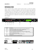
Overview
The Soloist 4111 HD Digital Media Server and the edje 4111 HD
Digital Media Player are designed for AVC/H.264 and MPEG 2 high
definition and standard definition file playback and IP stream decoding.
Whatever your source, the player or server can automatically scale the
content to match your output target up to 1080i for outstanding HD
playback. The media can easily be loaded, managed and scheduled for
playout using the included mediaControl software. With the Soloist 4111
and edje 4111 HD, you get unattended playout of high definition video
perfect for digital signage, kiosks and trade shows.
Applications
• Retail: Impress customers with high definition (HD) retail digital
signage and point of purchase advertising.
• Trade Shows and Museums: Get the detail you need with HD
playback on kiosks and syncronized interactive displays.
• Private IP Networks: Stream content to the edje HD and Soloist
HD over IP for point-to-point or multicast playout.
Benefits
• Play AVC/H.264 MPEG-2 HD: Step up to stunning playback
of high definition AVC/H.264 and MPEG-2 media with full 5.1 AC-3
audio.
• Automatically Scale SD to HD: Play both SD and HD content
with the same server or player which automatically sizes video with
advanced scalar algorithms to the desired output resolution up to
1080i.
• Control Playout: The Soloist 4111 HD and edje 4111 HD include a
built in command interface and scheduler that can play a list of files
when you want them and loop indefinitely.
• Synchronize Playback: Hook up two or more servers on the same
network and get synchronized playback of your content.
• Display Graphics and Video: Squeeze video and place graphics
anywhere on the screen for the best presentation impact.
• Manage Content: The included mediaControl application lets you
manage media and schedules on the server while controlling the
playout.
• Tune into IPTV Networks: Tune in and decode IP Multicast HD
content with fall back playout of stored content.

5Chapter 1 - Introduction
Availability
Model Description
edje 4111 HD
80GB internal storage digital media player
Soloist 4111 HD
300GB internal storage digital media server
EXTPS24WATT
External 12 volt power supply 24 watt for edje 4111HD.
DVI/COMPONENT
DVI to Component video cable
DVI-D/DVI-D
DVI to DVI-D video cable
DVI-A/VGA
DVI to VGA cable
DVI/HDMI
DVI to HDMI cable
DVI/RGBHV
DVI to RGBHV cable
What’s Included
edje 4111 HD
• edje 4111 HD with power cord
• mediaControl application control and configuration software
for Windows 2000/XP or Macintosh OX X (10.2 or greater).
• Terminal Kit: Ethernet cable, serial adapter
• Manual
Soloist 4111 HD
• Soloist 4111 HD with power cord
• mediaControl application control and configuration software
for Windows 2000/XP or Macintosh OX X (10.2 or greater).
• Terminal Kit: Ethernet cable, serial adapter
• Media cable (S-Video, BNC Composite Video, RCA SPDIF Audio)
• Manual
System Requirements
mediaControl Application
mediaControl configuration and control application requires one of the
following:
• Windows 2000 or XP or Linux computer: Intel or AMD 32 bit
processor at 2 GHz; 512MB memory; 1024x768 32 Bit color capable
graphics card; TCP/IP compatible computer network.
• Macintosh OS-X (10.2 or greater) computer: G4 32 bit processor at
1 GHz, G5 64 bit processor (any); 512MB memory; 1024x768 32 Bit
color capable graphics card; TCP/IP compatible computer network.
Note: Specifications subject to change without written notice
This documentation reflects functionality of Adtec Digital’s Soloist 4111 HD
and edje 4111 HD. Please refer to the Adtec website for updated documentation.
www.adtecinc.com/support/

Chapter 1 - Introduction
6
Front Panel Diagram - Soloist 4111 HD
Figure 1.1
Power
Off: no power
On
: power
Alarm
Off: no alarm
Yellow
: any soft alarm detected
Red: any alarm detected
Link
Off: no link detected
Green: link active
Busy
Off: no traffic
Green Flashing: traffic
Storage
Off: No storage attached (default)
Green Flashing: storage traffic
Navigational Keys
Up, Down, Left and Right
Mode
Select
Escape
Ente
r
Video
Off: not enabled (audio only )
Green: video present
Yellow
: unstable video
Red:
no video present
Alarm
Off: no alarm
Red:
decoder alarm
Multicast
Off: Not receiving multicast
channel stream
Green: Decoding multicast
stream
Audio
Off: not enabled
Green: audio present
Yellow
: unstable audio
Red: no audio present
Display Targets
Green: A green light indicates
the configured decoding
resolution
.
Play
Off: Decoder is idle
Green: File is playing

7Chapter 1 - Introduction
Rear Panel Diagram - Soloist 4111 HD
Figure 1.2
Label Function
AC Line Input
Standard 3-pin computer power plug. (Auto range 70-240 VAC input)
Analog Audio Out
Unbalanced analog stereo audio out (1/8” female)
Digital Video Out
Digital Video Interface (DVI-I) supports both digital (DVI-D) and analog (DVI-A) outputs for VGA and Component (RGB/YUV) with an
optional cable. Refer to Appendix E for pinout specifications.
7-Pin Media Port
Video & digital audio out configurable to Composite (BNC), SPDIF, S-Video (4-pin mini-din Y/C). Cable required for VGA, YUV and RGB.
GIGE
Gigabit Ethernet RJ-45 jack
FireWire
IIEE1194 FireWire Reserved for future use
Terminal Monitor
RS-232 terminal monitor for communicating with the internal host motherboard for diagnostics. Use the enclosed Ethernet cable with
the RJ-45 to RS-232 adapter for connection to a host computer. Default COM settings are 115,200 baud, 8 data bits, No Parity, 1 stop bit
and no flow control.
Ethernet
10/100BaseT Ethernet RJ-45 jack
USB
USB 2.0 host Reserved for future use
RS232
RS-232 Adtec API control and status terminal port. Default COM settings are 38,400 baud, 8 data bits, No Parity, 1 stop bit and no flow
control.
Parallel Port
Parallel port used for input or output control.
AC Line
Input Ethernet RS232
Parallel
Port
USB
Reserved for
future use
Terminal
Monitor
FireWire
Reserved for
future use
GIGE
Media
PortDVI-I
Analog
Audio

Front Panel Diagram - edje 4111 HD
Figure 1.3
Navigational Keys
Up, Down, Left and Right
Mode
Select
Escape
Ente
r
Power
Off: no power
On
: power
Alarm
Off: no alarm
Yellow
: any soft alarm detected
Red:
any alarm detected
Video
Off: not enabled (audio only )
Green: video present
Yellow
: unstable video
Red:
no video present
Multicast
Off: Not receiving multicast
channel stream
Green: Decoding multicast stream
Ethernet
Off: on link detected
Green: link active

Back Panel Diagram - edje 4111 HD
Figure 1.4
Label Function
AC Line Input
Standard 3-pin computer power plug. (Auto range 70-240 VAC input)
DC Input
12 VDC (Do NOT connect AC and DC concurrently) Purchase the 12VDC power supply from Adtec
separately (PN EXTPS24WATT)
Digital Video Out
Digital Video Interface (DVI-I) supports both digital (DVI-D) and analog (DVI-A) outputs for VGA and
Component (RGB/YUV) with an optional cable. Refer to Appendix E for pinout specifications.
Audio Left Unbalanced analog audio left channel (RCA)
Audio Right
Unbalanced analog audio right channel (RCA)
Audio SPDIF Digital audio (RCA) configurable as Compressed (for 5.1 AC-3 audio) or
Uncompressed (PCM 2 channel.
Parallel Cntl I/O Parallel port used for input or output control.
K Kensington Security Slot to be used with a Kensington Slim MicroSaver security
cable to prevent unauthorized removal of the server.
Com1 (not an API port)
RS-232 terminal monitor for communicating with the internal host motherboard for diagnostics. Use
the enclosed Ethernet cable with the RJ-45 to RS-232 adapter for connection to a host computer.
Default COM settings are 115,200 baud, 8 data bits, No Parity, 1 stop bit and no flow control.
Com2 (API)
RS-232 Adtec API control and status terminal port. Use the enclosed Ethernet cable with the RJ-45
to RS-232 adapter for connection to a host computer. Default COM settings are 38,400 baud, 8 data
bits, No Parity, 1 stop bit and no flow control.
Ethernet
10/100BaseT Ethernet RJ-45 jack.
CAUTION
HIGH VOLTAG
E
DC Input
AC Input
Audio Left
Audio Right
Audio SPDIF
Digital Vi
deo
Parallel Cntl I/O
K
K
COM 1 COM 2
Ethernet

Chapter 2 - Playe r & S e r ver Installation
10
Chapter 2 - Player & Server Installation
This chapter covers the setup of the Soloist 4111 HD Media Server
and edje 4111 HD Media Player.
Logging In and Out
The front panel of the Soloist 4111HD and edje 4111HD features
login security so that configurations made on the front panel are
protected. By default the servers come in a logged in state on the front
panel and will remain logged in (even after a reboot) until you manually
log out.
Log Out
- Press the “Mode” button until the SYSTEM MENU is displayed, then press
“Select”.
- Press the Down arrow until the Menu Login is displayed, then press
“Select”.
- When prompted to Log Out?, press “Enter” to log out.
Log In
- Press the “Mode” button until the SYSTEM MENU is displayed, then press
“Select”.
- Press the Down arrow until the Menu Login is displayed, then press
“Select”.
- Press the following key sequence to log in: “Up arrow”, “Select”, “Enter”,
“Right” and then “Enter”. Note that the key sequence spells the word
U-S-E-R.
Setup the Soloist 4111 HD
The Soloist 4111HD server should be installed into a one-rack unit
19” rack slot. Power should be applied to the unit and configured with a
valid IP address and display target via the front panel.
1. Setup the IP Address
- Press the “Mode” button until the SYSTEM MENU is displayed, then press
“Select”.
- Press the Down arrow until the NETWORK MENU is displayed, then press
“Select”.
- Press the Down arrow until the Ethernet (eth0) IP Address item is shown.
Enter the IP address of the Soloist using the “Select” and arrow buttons,
then press “Enter” to save.
* Note: The Ethernet (eth0) IP Address and IP Mask are the
settings for the Ethernet port on the back of the Soloist used for control
communication. Make sure that this port is on the same network as the
mediaControl computer.
- Press the Down arrow button for the Ethernet (eth0) IP Mask. Enter the
IP Mask using the “Select” and arrow buttons, then press “Enter” to save.
- If you are using the Soloist to receive IP Multicast, press the down arrow
and configure the GIGE (eth1) IP Address and Mask for the GIGE port on
the back of the Soloist.
* Note: Make sure the GIGE and Ethernet settings are on a separate
octet.
2. Setup the Display Target
- Press the “Mode” button until the DECODER MENU is displayed, then
press “Select”.
- Press the Down arrow until the Display Target is displayed. To change
the output display resolution, press “Select” and navigate to the desired
resolution and then press “Enter” to save.
* Note: The display target setting is the output resolution and
refresh rate used simultaneously on both the DVI and the composite

11Chapter 2 - Player & S e r v e r Installation
BNC video outputs. Therefore to view video on the composite BNC
output port, select one of the NTSC or PAL display targets. All the other
resolutions are appropriate for the DVI output.
3. Setup NTP Server (optional)
If you will be doing scheduled playback of content, it is
recommended to configure the server to an NTP network time server as
follows:
- Press the “Mode” button until the SYSTEM MENU is displayed, then press
“Select”.
- Press the Down arrow until the NTP MENU is displayed, then press
“Select”.
- Press the Down arrow until the NTP Server IPA item is shown. Enter the
IP address of the NTP server using the “Select” and arrow buttons, then
press “Enter” to save. Note: Entering 0.0.0.0 as the IPA will cause the
server to synchronize with its own time.
4. Make Cable Connections
Unplug the Soloist and make the following cable connections for
your setup:
Video: Connect your monitor to either the DVI connector or the composite
BNC connector using the 7 pin media port adapter included with the
Soloist.
Audio: Connect to either the 1/8” unbalanced analog audio port or the
S/PDIF digital audio RCA port on the 7 pin media port adapter cable.
Ethernet: Connect an Ethernet cable to the Ethernet port for external
control by mediaControl.
GIGE: Optionally connect the GIGE port to your IP Multicast network. Note
that the control network and the multicast network must be on separate
unique subnets.
Plug in the Soloist 4111HD and confirm that the IP address is
correct on your unit and that the Link LED on the front of the unit is lit
before installing the mediaControl application.

Chapter 2 - Playe r & S e r ver Installation
12
Setup the edje 4111HD
Up to two edje 4111HD servers can be installed into a one-rack
unit 19” rack slot using an optional tray available from Adtec. Power
should be applied to the unit and configured with a valid IP address and
display target via the front panel.
1. Setup the IP Address
- Press the “Mode” button until the SYSTEM MENU is displayed, then press
“Select”.
- Press the Down arrow until the NETWORK MENU is displayed, then press
“Select”.
- Press the Down arrow until the Ethernet IP Address item is shown. Enter
the IP address of the edje using the “Select” and arrow buttons, then press
“Enter” to save.
* Note: The Ethernet IP Address and IP Mask are the settings of the
Ethernet port on the back of the edje used for control communication.
Make sure that this port is on the same network as the mediaControl
computer.
- Press the Down arrow button for the Ethernet IP Mask. Enter the IP Mask
using the “Select” and arrow buttons, then press “Enter” to save.
2. Setup the Display Target
- Press the “Mode” button until the DECODER MENU is displayed, then
press “Select”.
- Press the Down arrow until the Display Target is displayed. To change
the output display resolution, press “Select” and navigate to the desired
resolution and then press “Enter” to save.
* Note: The display target setting is the output resolution and
refresh rate used simultaneously on both the DVI and the composite
BNC video outputs. Therefore to view video on the composite BNC
output port, select one of the NTSC or PAL display targets. All the other
resolutions are appropriate for the DVI output.
3. Setup NTP Server (optional)
If you will be doing scheduled playback of content, it is
recommended to configure the server to an NTP network time server as
follows:
- Press the “Mode” button until the SYSTEM MENU is displayed, then press
“Select”.
- Press the Down arrow until the NTP MENU is displayed, then press
“Select”.
- Press the Down arrow until the NTP Server IPA item is shown. Enter the
IP address of the NTP server using the “Select” and arrow buttons, then
press “Enter” to save. Note: Entering 0.0.0.0 as the IPA will cause the
server to synchronize with its own time.
4. Make Cable Connections
Unplug the edje and make the following cable connections for your
setup:
Video: Connect your monitor to either the DVI connector or the composite
BNC connector.
Audio: Connect to the 1/8” unbalanced analog audio port.
Ethernet: Connect an Ethernet cable to the Ethernet port for external
control by mediaControl.
Plug in the edje and confirm that the IP address is correct on your
unit and that the Link LED on the front of the unit is lit before installing
the mediaControl application.

13Chapter 2 - Player & S e r v e r Installation

Chapter3 - mediaControl Setup
14
Chapter 3 - mediaControl Setup
mediaControl is the control application for Adtec players and
servers. It offers list and schedule building as well as file management
and player control. On the following page is an overview of the
mediaControl application.
Installation of mediaControl
For Windows: The mediaControl software can be installed on
Windows XP and 2000 machines. Refer to the system requirements
in Chapter 1 for additional information. Insert the installation CD
into your computer. The install program will automatically launch. If
it does not, locate the CD drive via “My Computer” and double-click
the mediaControl Installer icon. The wizard will walk you through the
installation process. After installation, the icon for the application can be
found on the desktop and in the start menu in the mediaControl folder.
For MAC: The mediaControl software can be installed on MAC OSX
(10.2 or greater). Refer to the system requirements in Chapter 1 for
additional information. Insert the installation CD into your computer.
When the CD appears on the Desktop, double-click on the icon and then
on the mediaControl Installer icon. The wizard will take you through the
installation process. After installation, the launch icon for the application
can be found on the dock and in the Applications/Adtec/bin/ folder.
Navigation Panel
Once mediaControl has been installed on your desktop, you will be able to
configure your settings and connect to your player or server. You will see the
following headers available in the navigation panel of mediaControl.
Connect - Allows you to add, edit and save connections to your player
or server. All saved connections will be listed below this header.
Control - The control section of the navigation panel allows you to
build a list or schedule for your unit.
Manage - Manage provides you with a file management tool that will
allow you to move files between your player or server and your PC.
Configure - Configure has several sub headers that allow you
to configure Network, Playout, Channel, Graphics, Scaling and
Command Actions.
Tools - The Tools section assists you in upgrading your server, player
or mediaControl software. You also have the ability to view logs and
issue commands to your player or server via the Terminal interface.
Help - General version information and Technical Support.

15Chapter3 - mediaControl Setup
Figure 3.1

Chapter3 - mediaControl Setup
16
Configuration from mediaControl
Before you configure your player or server settings, you will need
to estabilsh a connection. You can create and manage connections to
more than one server with mediaControl.
mediaControl Connections
Launch the mediaControl application. mediaControl will display
a popup window showing you the connection status. If this is the first
time using mediaControl, it will attempt to connect via the default IP
settings that are established on the
servers and players. Otherwise,
mediaControl will attempt to connect
to the last player or server it was
connected to prior to shutting down.
Create a new connection
- Click on the Connect header in the navigation panel of mediaControl to
create a new connection. (Fig 3.2)
-
Figure 3.2
Enter a unique name in the Description field and the correct IP Address (the
Ethernet IP Address of your edje or Soloist). If you need to override the
default connection settings (useful with NAT port forwarding in firewalls) click
on Advanced to enter the desired port values for FTP and the Adtec API and
the password for your media server.
- Click Save and the settings are automatically saved.
- To open that connection, you can double-click on the connection name in the
navigation panel click on the connect button from the Connections Configure
Panel.
Once mediaControl is running, your connection status will show in
the Connetion Status section of the mediaControl Application window.
When connected, you can disconnect by closing the application or by
connecting to a different unit. To do this, simply double-click on the
name of the new server/player you want to connect to in the navigation
panel.
Edit an existing connection
- Select the desired connection on the left sidebar of mediaControl. Note that
mediaControl installs with one profile called Default, but you can make as
many profiles as you want.
- Enter the desired description and the correct IP Address of your edje or
Soloist. If you need to override the default connection settings (useful with
NAT port forwarding in firewalls) click on Advanced to enter the desired port
values for FTP and the Adtec API and the password for your media server.
- Click Save and the settings are automatically saved.
Delete a connection
- Select the connection you want to delete on the left sidebar of mediaControl.
- Click Delete and the connection settings are deleted.

17Chapter3 - mediaControl Setup
Networking
The Networking configuration page is used to configure the
network settings of the media server. (Fig 3.3) If you make changes to
the network settings, mediaControl will prompt you to save the changes
to the current connection profile and reconnect.
Figure 3.3
Communication
Ethernet IP Address:
The IP Address of the Ethernet port of the media server.
Ethernet Subnet Mask:
The subnet mask of the Ethernet port of the media server.
GIGE IP Address:
The IP Address of the GIGE port of the media server.
GIGE Subnet Mask:
The subnet mask of the GIGE port of the media server.
Gateway IP Address:
The IP Address of the gateway router to the WAN.
Server UserName:
The user name of the media server used on the Adtec API, FTP and Telnet
ports is currently fixed to “adtec” and cannot be changed.
Server Password:
The password used to access the media server on the Adtec API, FTP and
Telnet ports. The factory default is the word “none”.
File Transfer
FTP Command Port:
The command port number used by the FTP server on the media server.
The factory default is 21.
FTP Data Port:
The data port(s) used by the FTP server to respond to the FTP client. The
data port can be one value or a range in the format 1025,65535
Host
The host settings are used to configure how the media server connects to a
central server for content.
Host Mode:
- Client: (default) The media server is a stand alone client and will not
mirror from a server.
- MirrorList: The media server will connect to an FTP server and copy all
items in the list.
- MirrorServer: The media server will connect to an FTP server and mirror
all content in the folder.
Host IP Address:
The IP address of the FTP server.
Client User Name:
The user name the media server should use to connect to the FTP server.
Client Password:
The password the media server should use to connect to the FTP server.
Date & Time
Day, Date and Time:
The date and time that will be set in the real time clock on the media
server.

Chapter3 - mediaControl Setup
18
Time Zone:
The time zone list includes the major US time zones with daylight saving
time rules and UTC as a range from -12 to 0 to 12.
Multicast
Multicast Timeout:
The time in milliseconds for return to normal video playback after video
multicast packets are no longer detected. The default timeout value is 1000
milliseconds. If the timeout value is set too low, the multicast receive may
timeout during normal reception if the packet transmission is bursty.
Page is loading ...
Page is loading ...
Page is loading ...
Page is loading ...
Page is loading ...
Page is loading ...
Page is loading ...
Page is loading ...
Page is loading ...
Page is loading ...
Page is loading ...
Page is loading ...
Page is loading ...
Page is loading ...
Page is loading ...
Page is loading ...
Page is loading ...
Page is loading ...
Page is loading ...
Page is loading ...
Page is loading ...
Page is loading ...
/