Adtec Soloist 2 User manual

Type
User manual

This manual is also suitable for

Adtec Soloist 2, a reliable broadcast tool, offers high-quality video and audio playback with versatile connectivity options. It supports various video outputs, including composite, Y/C, component, and RGB, along with balanced and unbalanced audio outputs. Control the device via parallel, serial, or Ethernet interfaces. Its compact design allows for rack mounting or tabletop use, making it suitable for professional and home entertainment applications.

Adtec Soloist 2, a reliable broadcast tool, offers high-quality video and audio playback with versatile connectivity options. It supports various video outputs, including composite, Y/C, component, and RGB, along with balanced and unbalanced audio outputs. Control the device via parallel, serial, or Ethernet interfaces. Its compact design allows for rack mounting or tabletop use, making it suitable for professional and home entertainment applications.

Broadcast MPEG 2 Player
MPEG 2 Player
User Manual
Sales/Customer Service/Technical Support
Adtec, Inc.
408 Russell Street
Nashville, TN 37206
(615) 256-6619
Fax: (615) 256-6593
Sales: (615) 256-6619
Technical Support: (615) 256-7753
Manufacturing and Engineering
Adtec, Inc
2231 Corporate Square Blvd.
Jacksonville, FL 32216
WWW.ADTECINC.COM
Table Of Contents
i. Contact Information
ii. Safety Information
I. Soloist 2 Introduction
II. Mirage Introduction
III. Installing Symphony Software on your PC
IV. Symphony Software Screen Orientation
Main Screen
Terminal
Location
Console
Directory
Configuration
List
Schedule
File Manager
IFP
V. Connecting Symphony Software with a Mirage/Soloist
VI. In Field Programming (IFP) for Mirage/Soloist 2
Firmware Upgrade
VII. Ethernet Connection Guide for Mirage/Soloist 2
VIII. Technical
Control Interface Diagrams
Communications Diagrams
MPEG Storage (Data rate) Table
MPEG Encoding Parameters for Mirage/Soloist
SOLOIST 2 Introduction
BROADCAST MPEG 2 PLAYER Version 4.0
Soloist 2 Intro-Page 1 of 5
ADTEC, Inc. USA
Soloist 2
Introduction
Introduction
Soloist 2 Introduction
The Soloist 2 represents years of engineering and market research culminating
into one simple, reliable, economical and powerful broadcast tool. At its core,
the Soloist 2 utilizes a high-speed 32-bit RISC CPU operating under ADTEC’s
own deterministic multitasking operating system. The core CPU is tightly
integrated with MPEG decoding, memory, drive host control and digital to
analog circuitry to provide the highest level of quality and reliability available.
The Soloist 2 will provide years and years of total maintenance free operation
without the need or knowledge of sophisticated computers and operating
systems.
Identifier
Description
A
Reset switch. Must be held for one second to initiate reset.
B
Power LED, illuminates when AC power is applied to unit.
C
Video LED, illuminates during video playback.
D
Drive LED, illuminates during either SCSI or IDE host controller activity.
E
Link LED, illuminates when the electrical 10 Base T Ethernet connection is made
correctly to a hub or server.
F
Busy LED illuminates when Ethernet activity occurs.
G
Drive bay for primary, IDE or SCSI
H
Drive bay for secondary, IDE or SCSI
Soloist 2 Front with two removable hard drives
SOLOIST 2 Introduction
BROADCAST MPEG 2 PLAYER Version 4.0
Soloist 2 Intro- Page 2 of 5
ADTEC, Inc. USA
Soloist 2
Introduction
Introduction
Connector
Description
A
Chassis ground.
B
AC line input, 3-pin computer power plug. Includes 6’ cable. (Auto range 70-240 VAC input)
C
SOLO210BASET (10 Base T) and External SCSI 2 drive expansion port. Expansion port 2.
D
SOLO2BALYC (Balanced audio, Y/C, RGB, YUV) expansion port. Expansion port 1.
E
RS422A control port.
F
Parallel control port.
G
RS-232 communications port THRU. (Unlimited loop-through capabilities)
H
RS-232 communications port IN. (Unlimited loop-through capabilities) Units require unique names to
address individually.
I
Product label area.
J
10 Base T Ethernet Busy LED. (Only used when installed in Soloist 1 to Soloist 2 upgrade)
K
10 Base T Ethernet Link LED. (Only used when installed in Soloist 1 to Soloist 2 upgrade)
L
10 Base T Ethernet RJ-45 jack.
M
Ethernet hardware address. (48 bit MAC address set in hardware. IP address set by user.)
N
Balanced RIGHT audio output, 600 Ohm output impedance.
O
Balanced LEFT audio output, 600 Ohm output impedance.
P
Y/C output. 4 pin din connector.
Q
Y output of Y/C on BNC connector or Composite video in RGB and YUV modes.
R
C output of Y/C on BNC connector. R or RY signal for RGB or component modes
respectively.
S
Video output number 1, 75 Ohm. G or GY signal for RGB and Composite modes
respectively.
T
Video output number 2, 75 Ohm. B or BY signal for RGB and Composite modes
respectively.
U
SYNC input, 75 Ohm, Black Burst or Digital TTL sync or Genlock
V
Unbalanced LEFT audio output, 56K Ohm output impedance.
W
Unbalanced RIGHT audio output, 56K Ohm output impedance.
Soloist 2 rear panel
SOLOIST 2 Introduction
BROADCAST MPEG 2 PLAYER Version 4.0
Soloist 2 Intro- Page 3 of 5
ADTEC, Inc. USA
Soloist 2
Introduction
Introduction
Physical Concerns
Rack Mount Applications:
The Soloist 2 was designed to be rack mounted and requires only one rack unit
(1RU). It does NOT require blank spaces above or below to remain within it’s
designed operating temperatures. The Soloist 2 integrates a built in fan with side
panel discharge, make sure the side discharge has at least 1” of clear space to
allow for airflow.
Non Rack Mount Applications:
The Soloist 2 can be tabletop or desk mounted as it ships with four rubber feet to
prevent skid or slipping on Formica finishes. In this application, make sure that
no heavy objects (over 25 pounds) are placed on top of the unit as this may
cause damage to the drives.
Power Concerns
Power Supply:
The Soloist 2 ships with a six (6) foot standard SJT power cord with a three (3)
pin US type plug. A European 3 PIN cord with plug is available on PAL
versions. The unit incorporates a universal input switch mode power supply. It
carries the CE, UL, CSA and TUV safety certifications. Valid input ranges from
70 to 240 volts AC (VAC), 50 Hz or 60 Hz and uses between 20 and 65 watts
based on the number and type of hard drive(s) used.
Video Concerns
Video Connections:
The SOLOIST 2 uses video industry standard BNC connectors for video and
SYNC connections. YC is available via two BNC connectors or a 4-pin din
connector. In addition, a four (4) pin din connector and two BNC connectors are
supplied for Y/C video out.
\
Units can be rack mounted with
out blank panels between them.
%
The Soloist 2 can be configured for
Composite, YC, Component
(Separate SYNC), and RGB
(SYNC). See Configuration for
more specifics.
%
Sync on Green for RGB and Sync
on Y for Component is available
with the SOLO2SYNCGREEN
hardware option.
M
Caution: The 4-pin din and two
BNC connectors are the same
electrical YC signal, both CAN
NOT be connected at the same
time!
SOLOIST 2 Introduction
BROADCAST MPEG 2 PLAYER Version 4.0
Soloist 2 Intro- Page 4 of 5
ADTEC, Inc. USA
Soloist 2
Introduction
Introduction
Audio Concerns
Audio Connections:
The Soloist 2 ships standard with RCA jack, Unbalanced (Hi impedance -10 dB,
56 K Ohm) audio connectors for left and right channels. Removable Screw
Terminal (RST) connectors are supplied to facilitate low impedance (+4 dB, 600
Ohm) balanced audio.
Communications Concerns
Control Connectors:
The SOLOIST 2 incorporates control via Parallel, Serial RS232, Serial RS422A,
and Ethernet (Telnet). The Parallel port utilizes a DB9 male connector, the
RS422A port utilizes a DB9 female connector, and the RS232 ports utilize RJ-
11 telephone connectors. The Ethernet uses RJ-45 connection through your
existing Lan/Wan system. For specific information regarding the protocol and
pin out, see the Technical section.
Communications Connections:
The SOLOIST 2 provides multi drop loop-through RS232 to allow a single PC
communications port or serial controller access to multiple units. Two RJ-11
connectors make up the In and Thru connections. Adapters are provided to
connect the SOLOIST 2 directly to a 9-pin PC communications port. Ethernet
communication is facilitated via the RJ-45 connector on the Ethernet port of the
Soloist 2. The Ethernet port is provided on the Soloist 2; however, it is up to the
customer to provide cabling and connection to their Lan/Wan system. Please
consult your Network Administrator before installing the Soloist 2 in a Lan/Wan
environment.
%
The Soloist 2 can easily be
controlled via serial, parallel, or
Ethernet interfaces.
%
An unlimited number of units can
be controlled from one (1) RS232
serial port.
SOLOIST 2 Introduction
BROADCAST MPEG 2 PLAYER Version 4.0
Soloist 2 Intro- Page 5 of 5
ADTEC, Inc. USA
Soloist 2
Introduction
Introduction
Hard Drive Concerns
Internal Drive(s):
The Soloist 2 ONLY recognizes drives formatted using FAT 16. The DOS
FDISK and SCANDISK utilities support partition sizes of 2 Gigabytes;
however, the Soloist 2 can also partition and format drives with up to 4 Gigabyte
FAT 16 partitions. The Soloist 2 can see up to 32 partitions per physical drive
(128 Gigabytes/Drive). The Soloist 2 chassis can facilitate up to two (2) IDE or
SCSI-2 removable hard drives mounted in 5.25” removable bays. If more than
two (2) physical drives are required, an external storage chassis is required. The
Soloist 2 can interface with industry standard IDE (EIDE) ATA type hard
drives. It also can interface with SCSI-2 (50-pin narrow) hard drives. ATAPI
IDE CD-ROM or DVD-ROM drives may also be used as a source drive to copy
onto a hard drive. The data through put and media used with CD or DVD-ROM
drives are not reliable enough to use for consistent MPEG 2 video playback.
SCSI-2 Drive Expansion:
The Soloist 2 includes a knock out for a fifty-pin Centronics female connector.
The cable can be obtained from ADTEC. ADTEC offers a rack mount chassis
that holds up to eight (8) SCSI-2 devices (SCSI-2 is limited to seven (7)). The
external chassis is ideal for applications where large amounts of video are
required or for RAID applications.
Applications:
There is a section on our website to help you with implementation ideas. Please
be sure to check that out. www.adtecinc.com.
Summary:
The SOLOIST 2 was designed to replace VCR’s and Laser (Video) Disk
Players. It will provide many years of high quality reliable video and audio.
Should you require technical support or supplies contact ADTEC at 615-256-
6619 or www.adtecinc.com.
\
The Soloist 2 ONLY supports
SCSI-2 (50-pin narrow) and IDE
hard drives. Wide 68- pin drives
are NOT supported.
\
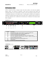
See Rear Panel view. Item C.
\
FAT 16 is the only file system the
Mirage/Soloist 2 recognizes.
Mirage partitioned and formatted
drives can be seen in Win 95, Win
98 and NT. Please note that
NTFS and FAT 32 are not
supported.
Mirage Introduction
MPEG 2 PLAYER Version 4.0
Mirage Intro-Page 1 of 5
ADTEC, Inc. USA
Mirage
Introduction
Introduction
Mirage Introduction
The Mirage represents years of engineering and market research culminating
into one simple, reliable, economical and powerful video tool. At its core, the
Mirage utilizes a high-speed 32-bit RISC CPU operating under ADTEC’s own
deterministic multitasking operating system. The core CPU is tightly integrated
with MPEG decoding, memory, drive host control and digital to analog circuitry
to provide the highest level of quality and reliability available. The Mirage will
provide years and years of total maintenance free operation without the need or
knowledge of sophisticated computers and operating systems.
Identifier
Description
A
Reset switch. Must be held for one second to initiate reset.
B
Power LED illuminates when AC power is applied to unit.
C
Video LED illuminates during video playback.
D
Drive LED illuminates during IDE host controller activity.
E
Drive bay for primary, IDE
Mirage Front with included removable IDE hard drive.
Mirage Introduction
MPEG 2 PLAYER Version 4.0
Mirage Intro- Page 2 of 5 ADTEC,
Inc. USA
Mirage
Introduction
Introduction
Connector
Description
A
Chassis ground.
B
AC line input, 3-pin computer power plug. Includes 6’ cable. (Auto range 70-240 VAC input)
C
Ethernet (10 Base T). Expansion port 2.
D
Balanced audio and Y/C port (Balanced audio, Y/C) expansion port. Expansion port 1.
E
Parallel control port.
F
RS-232 communications port THRU. (Unlimited loop-through capabilities)
G
RS-232 communications port IN. (Unlimited loop-through capabilities) Units require unique names to
address individually.
H
Power cord strain relief connections
I
10 Base T Ethernet Busy LED. (Requires optional Firmware and Internal Cable.)
J
10 Base T Ethernet Link LED. (Requires optional Firmware and Internal Cable.)
K
10 Base T Ethernet RJ-45 jack.
L
Ethernet hardware address. (48 bit MAC address set in hardware, IP address selected in firmware
configuration)
M
Balanced RIGHT audio output, 600 Ohm output impedance.
N
Balanced LEFT audio output, 600 Ohm output impedance.
O
Y/C output. 4 pin din connector.
P
Video output number 1, 75 Ohm.
Q
Video output number 2, 75 Ohm.
R
Unbalanced LEFT audio output, 56K Ohm output impedance.
S
Unbalanced RIGHT audio output, 56K Ohm output impedance.
Mirage rear panel with optional Balanced Audio/YC and 10 Base T Ethernet options
Mirage Introduction
MPEG 2 PLAYER Version 4.0
Mirage Intro- Page 3 of 5 ADTEC,
Inc. USA
Mirage
Introduction
Introduction
Physical Concerns
Rack Mount Applications:
The Mirage was designed to be rack mounted and requires only one rack unit
(1RU). It does NOT require blank spaces above or below to remain within it’s
designed operating temperatures.
Non Rack Mount Applications:
The Mirage can be tabletop or desk mounted as it ships with four rubber feet to
prevent skid or slipping on Formica finishes. In this application, make sure that
no heavy objects (over 25 pounds) are placed on top of the unit as this may
cause damage to the drives.
Power Concerns
Power Supply:
The Mirage ships with a six (6) foot standard SJT power cord with a three (3)
pin US type plug. A European 3 PIN cord with plug is available with PAL
versions. The unit incorporates a universal input switch mode power supply. It
carries the CE, UL, CSA and TUV safety certifications. Valid input ranges from
70 to 240 volts AC (VAC), 50 Hz or 60 Hz and uses between 20 and 65 watts
based on the type of hard drive used.
Video Concerns
Video Connections:
The MIRAGE uses video industry standard BNC connectors for composite
Video and a 4 pin din for YC connections.
Units can be rack mounted
without blank panels between
them.
%
The Mirage incorporates
Composite and YC video.
Mirage Introduction
MPEG 2 PLAYER Version 4.0
Mirage Intro- Page 4 of 5 ADTEC,
Inc. USA
Mirage
Introduction
Introduction
Audio Concerns
Audio Connections:
The Mirage ships standard with RCA jack, Unbalanced (Hi impedance -10 dB,
56 K Ohm) audio connectors for left and right channels. Removable Screw
Terminal (RST) connectors are supplied to facilitate low impedance (+4 dB, 600
Ohm) balanced audio.
Communications Concerns
Control Connectors:
The MIRAGE incorporates Parallel, Serial RS232 control, and Ethernet
(Telnet). The Parallel port utilizes a DB9 male connector and the RS232 ports
utilize RJ-11 telephone connectors. The Ethernet uses RJ-45 connection through
your existing Lan/Wan system. For specific information regarding the protocol
and pin out, see the Technical section.
Communications Connections:
The MIRAGE provides multi drop loop-through RS232 to allow a single PC
communications port or serial controller access to multiple units. Two RJ-11
connectors make up the In and Through connections. Adapters are provided to
connect the MIRAGE directly to a 9-pin PC communications port. Ethernet
communication is facilitated via the RJ-45 connector on the Ethernet port of the
Mirage. The Ethernet port is provided on the Mirage; however, it is up to the
customer to provide cabling and connection to their LAN/Wan system. Please
consult your Network Administrator before installing the Mirage in a LAN/Wan
environment.
%
The Mirage can easily be
controlled via serial, parallel, and
Ethernet interfaces.
%
An unlimited number of units can
be controlled from one (1) RS232
serial port.
S
ymphony – Net
Installing Symphony
SYMPHONY – NET DIGITAL SOFTWARE
Version 4.0
Installing Symphony-Page 1 of 1
ADTEC, Inc. USA
Installing Symphony
Installing Symphony
Installing Symphony Software
To install and run Symphony on a computer, first run the installation program.
It is recommended that you do not just copy Symphony files into a directory on
the hard disk, but copying the files to the hard disk drive will still allow the
software to function properly.
System Requirements
Minimum Required Hardware:
Pentium II or equivalent processor with 300 Mhz clock speed
32 MB RAM
SVGA with a minimum of 800 by 600 resolution and 64K
colors (True color and 1024 x 768 recommended).
Hard disk drive, one CD ROM drive, Modem and Network
Interface Card (NIC)
At least 10 MB free disk space
Recommended Hardware:
Pentium II, or higher processor (see above)
32 MB RAM
10 MB free disk space
Required Software:
Windows 95, Windows 98, or Windows NT Service Pack 3.0
or higher. (Workstation or server)
Standard Installation of Symphony Software
1. Insert the CD or floppy disks (older releases) into the computer’s CD
ROM drive.
2. Click Start Icon on your desktop.
3. Click Run and Browse CD or floppy for the Setup.exe file
4. Launch Symphony.exe file
5. Follow the installation steps.
Symphony does not use Microsoft
DLL Files. It consists of a single
executable file.
Updates are available at
www.adtecinc.com
.
Symphony Net Screen Orientation
SYMPHONY NET DIGITAL SOFTWARE Version 4.0
Symphony Screens-Page 1 of 11
ADTEC, Inc. USA
Symphony Screens
Symphony Screens
Screen Orientation
This section is intended to give an orientation of the Symphony Screens used by
the Mirage and Soloist 2. It will show the basic features and icons of each
screen. For a more in depth look at each section of Symphony software, please
refer to the Technical Manual for the Mirage and Soloist 2. The technical
Manual can be found on the enclosed CD-ROM or by going to our web site at
www.adtecinc.com.
Symphony Main Screen
1. Pull Down Menu
2. Modem Lights
3. Connection Information
4. Messages
1. Product Bar
2. Applet Icons
3. Connection Pull-down
%
Click Applets one time! Double-
clicking Applets will cause the
Application to open twice.
Symphony Net Screen Orientation
SYMPHONY NET DIGITAL SOFTWARE Version 4.0
Symphony Screens-Page 2 of 11
ADTEC, Inc. USA
Symphony Screens
Symphony Screens
Terminal
Terminal provides a text based editor to send or retrieve data. It is a way for
users to enter specific commands directly into the Mirage or Soloist 2.
1. Click Terminal Icon once to start.
2. Terminal Screen Click in Black area to begin typing commands.
3. Click the Scroll Up to view data not visible. Terminal will
store up to 256 lines of information. Make sure to click again prior to
entering new terminal commands
\
DO NOT use the <BACKSPACE>
key; typing errors will result. If
you do not type the correct
response, hit <ENTER> and start
over.
%
Symphony Terminal is similar to
Windows HyperTerminal.
%
The Commands used in Terminal
are the same commands as found in
the Command Interface portion of
the Mirage-Soloist Technical
Manual. Please refer to this
document for further descriptions
of Terminal Commands.
Symphony Net Screen Orientation
SYMPHONY NET DIGITAL SOFTWARE Version 4.0
Symphony Screens-Page 3 of 11
ADTEC, Inc. USA
Symphony Screens
Symphony Screens
Location
A Location contains information for connecting to a unit(s). This includes
information on names, phone (modem) number, port type, and the names of
each unit(s) at the Location. The Location area also has a section for storing site
contact information and pager settings.
Speed Bar
Open Save Close Add Loc Del Loc Previous Next Config Connect Contact
Contact Sheet
1. Multiple Locations
2. Location Information
3. Unit Names at Location
%
For information on creating a
Location to use in Symphony,
please refer to the Connection
guide in this document.
%
For more detailed information on
Location, please refer to the
Location Section of the Mirage-
Soloist Technical Manual.
%
Pager Settings work with Duet
MPEG2 Digital Ad-Inserter only.
Symphony Net Screen Orientation
SYMPHONY NET DIGITAL SOFTWARE Version 4.0
Symphony Screens-Page 4 of 11
ADTEC, Inc. USA
Symphony Screens
Symphony Screens
Console
Console is the Graphical User Interface (GUI) for the Mirage and Soloist 2. It
will allow the user to see the inventory of the Soloist in the Directory, Configure
the unit. Play a sequential list and play a Schedule according to Time and Date.
Control Panel
1. Control Panel
2. Console Applet
%
For more detailed information on
Console, please refer to the
Console Section of the Mirage-
Soloist Technical Manual.
  • Page 1 1
  • Page 2 2
  • Page 3 3
  • Page 4 4
  • Page 5 5
  • Page 6 6
  • Page 7 7
  • Page 8 8
  • Page 9 9
  • Page 10 10
  • Page 11 11
  • Page 12 12
  • Page 13 13
  • Page 14 14
  • Page 15 15
  • Page 16 16
  • Page 17 17
  • Page 18 18
  • Page 19 19
  • Page 20 20
  • Page 21 21
  • Page 22 22
  • Page 23 23
  • Page 24 24
  • Page 25 25
  • Page 26 26
  • Page 27 27
  • Page 28 28
  • Page 29 29
  • Page 30 30
  • Page 31 31
  • Page 32 32
  • Page 33 33
  • Page 34 34
  • Page 35 35
  • Page 36 36
  • Page 37 37
  • Page 38 38
  • Page 39 39
  • Page 40 40
  • Page 41 41
  • Page 42 42
  • Page 43 43
  • Page 44 44
  • Page 45 45
  • Page 46 46

Adtec Soloist 2 User manual

Type
User manual
This manual is also suitable for

Adtec Soloist 2, a reliable broadcast tool, offers high-quality video and audio playback with versatile connectivity options. It supports various video outputs, including composite, Y/C, component, and RGB, along with balanced and unbalanced audio outputs. Control the device via parallel, serial, or Ethernet interfaces. Its compact design allows for rack mounting or tabletop use, making it suitable for professional and home entertainment applications.

Ask a question and I''ll find the answer in the document

Finding information in a document is now easier with AI